Creating a Residence Layout, Seating plan, Toilet and Utility room plan using AutoCad
CREATING A RESIDENCE LAYOUT, SEATING PLAN, TOILET & UTILITY ROOM PLAN USING AUTOCAD
Jagadeep.M.M
AIM:
To draft the creating Residence Layout, Seating plan, Toilet & utility room plan using Autocad.
INTRODUCTION:
- Layers is a concept that allows you to group drawn geometry in distinct & separate categories according to similar features or a common theme.
- This allows you to exercise
control over your drawing by, among other things, applying properties to the layers, such as assigning colors & linetype.
- You can also manipulate each individual layer, making it visible or invisible for clarity, as well as being able to lock them to prevent editing. for example, all the walls of a floor plan will exist on the "walls" layer, all the doors on the "doors" layer, windows on the "windows" layer, & so on.
- You can think of layers as transparency sheets in an anatomy textbook, with each sheet showing a unique & distinct category of data, but when viewed all at once they show the complete picture of a person.
- Similarly, in Autocad ,there can be any number of layers. with all of them holding their respective data & combining into the complete design.
Challeng 1:
PROCEDURE:
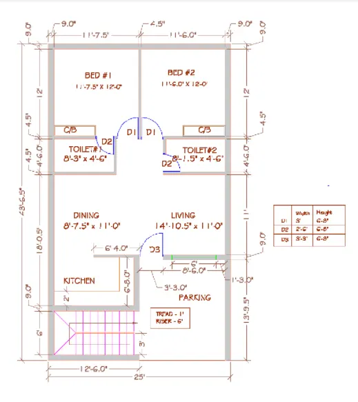
To sketch a residential plan using AUTOCAD softwere.
step 1:
To create the external & internal walls:
- Open autocad softwere, type QNew incommand box,press enter.
- Select default setting as imperial setting.
- Drawing units setting as length=(Engineering),precision=0'0.0", Ok
- Drawing limits setting as, specify the lower left corner=enter,upper right corner=100',100',enter.
- Type the command box Dimension style manager & press enter.
- enter modify-enter primary units-unit format=Engineering, precision=0'0.0",enter Ok.
- Type the "XL" in command box & press enter for construction line.
- Select vertical & click on screen anywhere.
- Type the "XL" in command box & press enter for construction line.
- Select horizontal & click on screen anywhere.
- Type the "TR" for trim command & trim the extra line to create bottom-left border of plan.
- Type the command "O" for offset & take the offset distance of 9" from both construction lines.
- Type the command "O" for offset & take the offset distance of 6' from the top horizontal lines.
- Type the command "O" for offset & take the offset distance of 9" from the top horizontal lines.
- Type the command "O" for offset & take the offset distance of 6'8" from the top horizontal lines.
- Type the command "O" for offset & take the offset distance of 4.5" from the top horizontal lines.
- Type the command "O" for offset & take the offset distance of 11' from the top horizontal lines.
- Type the command "O" for offset & take the offset distance of 9" from the top horizontal lines.
- Type the command "Fillet" correct the corner lines.
- Type the command "O" for offset & take the offset distance of 11'7.5" from the top vertical lines.
- Type the command "O" for offset & take the offset distance of 4.5" from the top vertical lines.
- Type the command "O" for offset & take the offset distance of 11'6" from the top vertical lines.
- Type the command "O" for offset & take the offset distance of 9" from the top vertical lines.
- Type the command "O" for offset & take the offset distance of 11" from the offset lines.
- Type the command "O" for offset & take the offset distance of 9" from offset lines.
- Now type the command "TR" & trim all the unwanted lines.
step 2:
To create staircase:
- For dividing the staircase give an offset of 3' from the front wall thickness.
- size of the theard 1' & size of the rise 6".
- Give the offset of 1' to draw the stairs in the plan view.
- Draw 9 offsets as there are 9risers for 8 steps.
- Trim the lines between handrails & give the other side as dotted line which indicates it is 1st floor stair case which is not visible when viewing ground floor plan view.
- For other side of the stairs chang line type to ISO dsh & mark the direction of stairs.
step 3:
To create door:
- Create the opening for respective doors using the width given in the table.
- Draw doors by creating an hinge 0f 0.5" from the midpoint of both the wall, then drawing a circle with one point on the midpoint of hinge & other at the midpoint of another hinge.
step 4:
To create window:
- For living room take an offset of 1'3" as given in the figure.
- Using the line command draw a line of 6' from the center of offseted line inside the wall thickness.
- Trim all the extra line using trim command.
step 5:
To create kitchen slab & cupboards:
- offset a distance of 2' to make the kitchen slab.
- Draw the cupboard by creating arectangle specifying the base point & give dimensionas 5'*1'5".
- Copy this rectangle to the other bedroom.
step 6:
To give dimensions:
- Type "D" & then press enter for dimension style management.
- set the dimension properties as per requirment.
- Type "DIM" in command box for dimension.
- Specify start & end points of the objects.
step 7:
To create Text:
- Select "TEXT" command from ribbon to create text.
- specify the first & last corner.
- Type the Text on the box & click anywhere in the screen to exit the command.
- Edit the height of text by selecting the text & clicking & selecting the properties option .
step 8:
Creating layer:
- Type "LA" & press enter to open layer property manager box.
- Create new layers by clicking on new layer icon or right click on existing layer & select new layer.
- Give names to the layers & assign different colours & line type if required.
- Select the diffrent components of drawing & assign the layer to them.
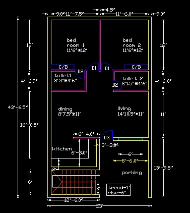
Result:
Challeng 2:
PROCEDURE:
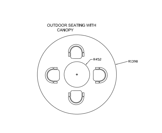
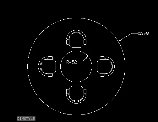
To sketch the seating plan for an outdoor canopy.
- Open autocad softwere, type QNew incommand box,press enter.
- Select default setting as imperial setting.
- Drawing units setting as length=desimal,precision=0,Insertion scale=Millimeters, Ok
- Drawing limits setting as, specify the lower left corner=enter,upper right corner=2000,2000,enter.
- Type the command box Dimension style manager & press enter.
- enter modify-enter primary units-unit format=desimal, precision=0,enter Ok.
- Draw a circle using circle command of radius 1398mm.
- Draw a circle using circle command of radius 452mm.
- draw the center line of the circle.
- draw the rectangle of length 400mm & width 200mm.
- Now draw an arc with start-center end with the endpoints & center of the length of the rectangle.
- Now give two offset of 50mm using offset command from the arc & join the end points of the offfseted acc.
- Draw another rectangle of length 100mm & width 50mm using rectangle command.
- Using the move command : select the base point & move to the required place.
- Using mirror command: mirror the chair to the opposit side by selecting base point.
- Using rotate command: rotate the chair & move it to the left side by selecting the base point.
- Again mirroring it to create the chair in the right side.
Result:
Challeng 3:
PROCEDURE:
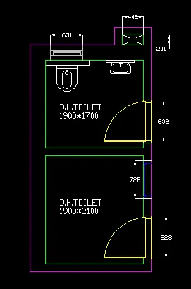
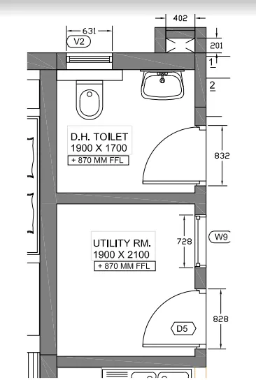
The Toilers & Utilities rooom.
step 1:
To create the external & internal walls:
- Open autocad softwere, type QNew incommand box,press enter.
- Select default setting as imperial setting.
- Drawing units setting as length=(Decimal),precision=0,Insertion scale=Millimeters, Ok
- Drawing limits setting as, specify the lower left corner=enter,upper right corner=3000,3000,enter.
- Type the command box Dimension style manager & press enter.
- enter modify-enter primary units-unit format=Decimal, precision=0,enter Ok.
- Type the "XL" in command box & press enter for construction line.
- Select vertical & click on screen anywhere.
- Type the "XL" in command box & press enter for construction line.
- Select horizontal & click on screen anywhere.
- Type the command "TR" for trim command trim the extra line to create bottom-left border of plan.
- Type the command "O" for offset & specify the offset distance 300mm & select the vertical Xline & click the cursor on right side.
- Type the command "O" for offset & specify the offset distance 150mm & select the horizontal Xline & click the cursor on upper side.
- Type the command "O" for offset & specify the offset distance 1900mm & select the Xline & click the cursor on right side.
- Type the command "O" for offset & specify the offset distance 150mm & select the vertical Xline & click the cursor on right side.
- Type the command "O" for offset & specify the offset distance 2100mm & select the horizontal Xline & click the cursor on upward direction.
- Type the command "O" for offset & specify the offset distance 150mm & select the horizontal Xline & click the cursor on upward direction.
- Type the command "O" for offset & specify the offset distance 1700mm & select the horizontal Xline & click the cursor on upward direction.
- Type the command "O" for offset & specify the offset distance 300mm & select the horizontal Xline & click the cursor on upward direction.
- Type the command "O" for offset & specify the offset distance 210mm & select the horizontal Xline & click the cursor on upward direction.
- Type the command "O" for offset & specify the offset distance 150mm & select the horizontal Xline & click the cursor on upward direction.
- Type the command "O" for offset & specify the offset distance 402mm & select the vertical Xline & click the cursor on right side to left direction.
- Type the command "O" for offset & specify the offset distance 150mm & select the vertical Xline & click the cursor on left side.
- Type "TR" for trim command & press enter.
- As per the sketch trim the unnecessary lines.
step 2:
- Type the command "O" for offset & specify the offset distance of 100mm & select the upper room mid-horizontal line & click the cursor on upward direction just for reference.
- Extend that line into the thickness of right side wall & trim the previous line.
- Type the command "O" for offset & specify the offset distance of 832mm & select the previous line & move the cursor in upward direction.
- Use trim command & trim the unwanted line.
- Draw the door of width 832mm using rectangle command.
- Select the arc tool from ribbon tab & specify the start point, end point & the direction as specify in sketch.
- Repeat the above same procedure to draw the next door of length 828mm.
step 3:
- Tyoe the command "O" for offset & specify the offset distance of 100mm & select the top-left line & click the cursor on right side & press "esc".
- Tyoe the command "O" for offset & specify the offset distance of 631mm & select the last offseted line & click the cursor on right side & press "esc".
- Select rectangle tool from ribbon tab & draw small rectangle of random size inside the offsetted lines & the join the edges of rectangle by using line command.
- Type the command "O" for offset & make two more offset in between at equal distance & press esc.
- Draw a horizontal line at the middle right side using line tool from ribbon tab.
- Type the command "O" for offset & specify the offset distance 728mm & select the line & click the cursor on downward direction & press esc.
- Use line command & draw a line in between the window & draw the small rectangle at each ends of line by using "rec" command.
step 4:
- Draw the toilet & Washbasin as given in the sketch by using line,fillet,rectangle,circle command.
- Type "TR" for trim command & press enter & then trim the unwanted lines.
Result: