Creating a Residence Layout, Seating plan, Toilet and Utility room plan using AutoCad
Week 4 Challenge 4
1.
AIM:
To sketch the layout of the residence plan as shown in figure, explain the procedure in detail and obtain the final result.
INTRODUCTION:
AutoCAD is a computer aided design software and drafting software application.
In this week by completing diagram 1 (Residence plan), I learned how to draw a layout of a Residence, using various commands like units, limits, zoom, Xline, offset, fillet, circle, lineweight, erase/trim, copy, mirror, texts.
By completing diagram 2 (outdoor canopy), I have learnt to create objects on assuming dimensions which would fit the area perfectly.
By completing diagram 3 (toilets and utility room), I have used the “layers functions” where I created separate layers for outer walls, inner walls, doors, windows and ventilation, texts.
I have explained the detailed step by step procedure.
PROCEDURE:
- Open AutoCAD software
- Choose Imperial (feets and inches) and start from scratch
- Set the units to Engineering and select ok
- Ensure the dynamic input is off.
- Specify the limits as lower left corner (0,0) and upper right corner (200’,200’)
- “Object snap
-
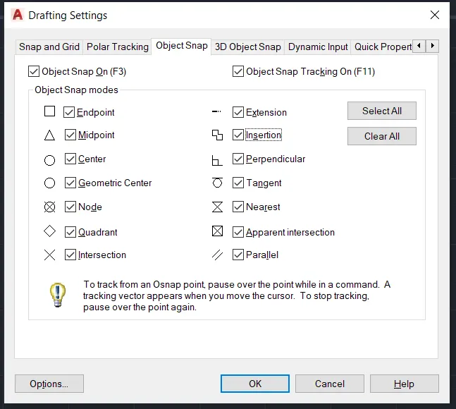
- Using command Xline(vertical), draw 2 lines at a distance of 25’.
- Using command Xline (horizontal), draw 2 lines at a distance of 43’6.5”.
- Using offset command, offset both vertical lines to 9” towards inside.
- Using offset command, offset both horizontal lines to 9” towards inside.
-
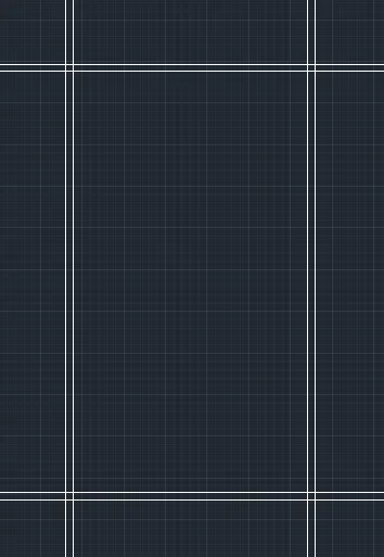
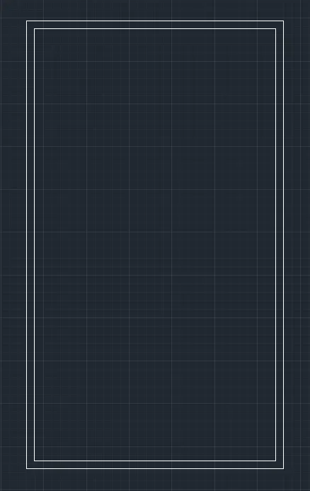
- Using fillet command, fillet (radius 0) the outer lines and inner lines.
-
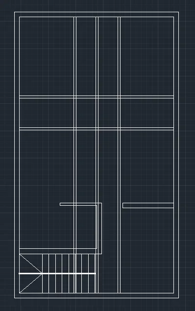
- Using offset command, offset the bottom horizontal line towards inside to a distance of 6’, again offset the previous line to 9”, again offset the previous line to 6’8”, again offset the previous line to 9” and Esc.
- Using offset command, offset the right vertical line towards inside to a distance of 11’9”, again offset the previous line to 9” and Esc.
-
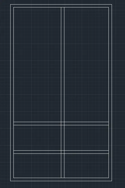
- Now, using fillet command, fillet (R0) the first intersection.
-
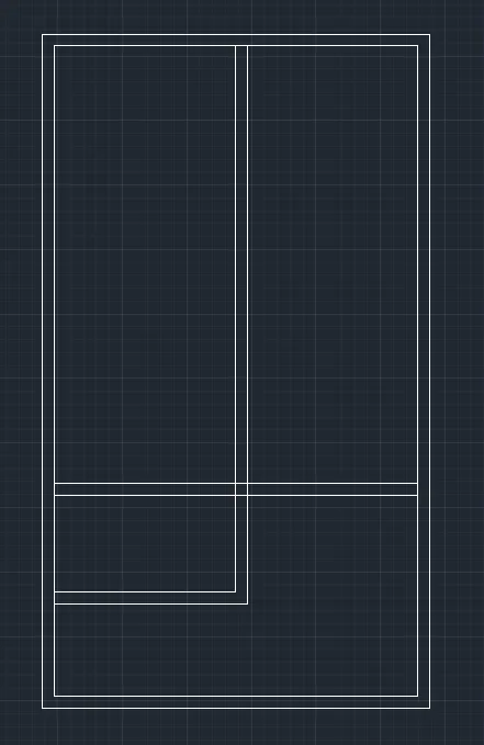
- Trim the center lines.
- To Leave a door space of 3’3” in the right, draw a reference line of 3’3” from the kitchen wall, close the area and trim the lines to get the gap.
-
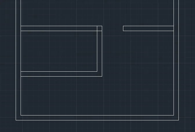
- To finish the kitchen wall, using offset command, offset the right wall from outside line (including wall thickness) towards inside to a distance of 6’4”.
- Now, using offset, make the north wall of thickness of 4.5”.
-
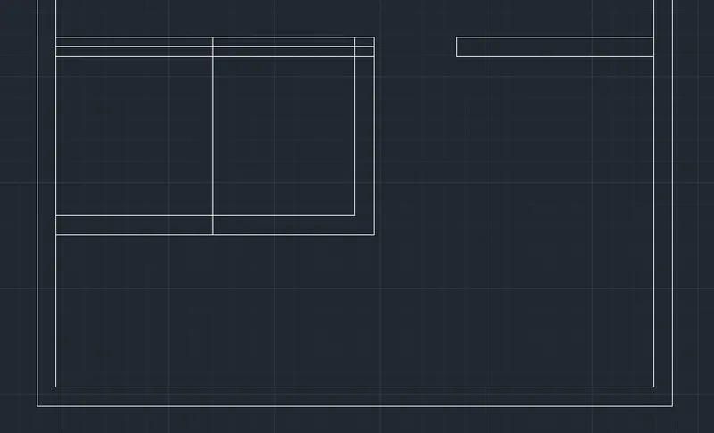
- Trim the extra lines to finish the kitchen area.
-
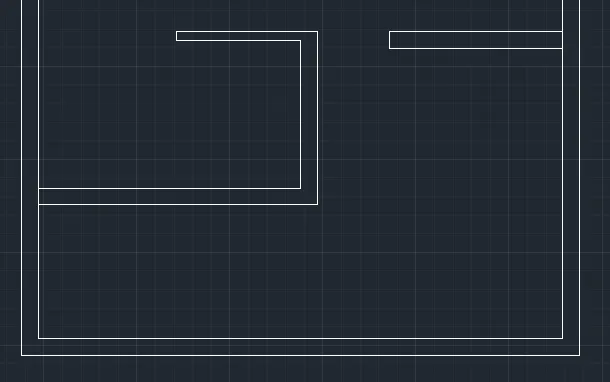
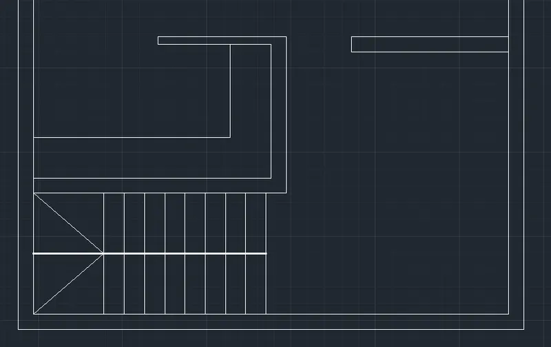
- Draw a vertical reference line connecting the kitchen wall to the outer wall.
- From the midpoint of the previous line, draw a horizontal line extends left side to the outer wall.
-
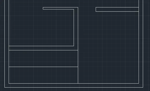
- Increase the line weight of the previous line to 0.30mm and display it.
-
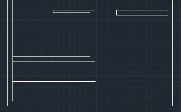
- Now, offset (multiple) the vertical reference line to a distance of 1’ for 8 times to form the stairs.
-
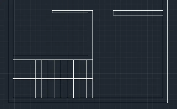
- Now, trim the reference line and join the diagonals in clockwise in the standing area.
-
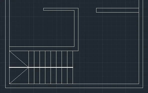
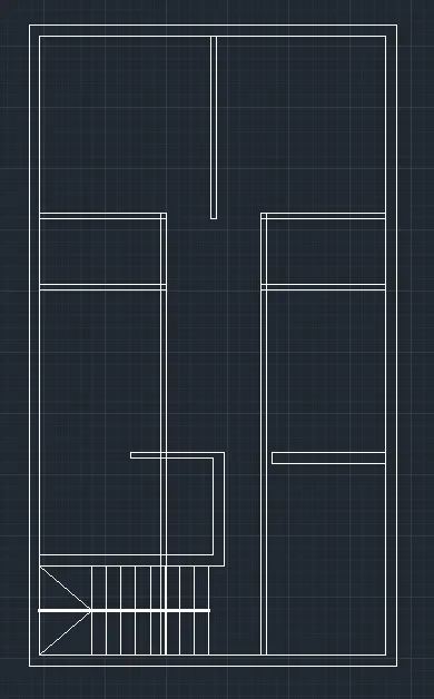
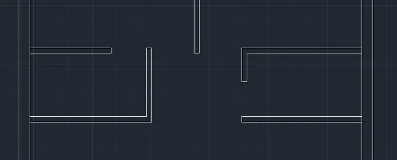
- Using offset command, offset the north wall of the plan (excluding wall thickness) towards inside to a distance of 12’, again offset the previous line to a distance of 4.5”, again offset the previous line to a distance of 4’6”, again offset the previous line to a distance of 4.5” and Esc.
- Using offset command, offset the west wall (excluding wall thickness) towards inside to a distance of 8’3”, again offset the previous line to a distance of 4.5” and Esc.
- Using offset command, offset the east wall (excluding wall thickness) towards inside to a distance of 8’1.5”, again offset the previous line to a distance of 4.5” and Esc.
-
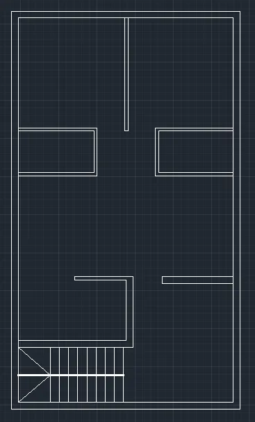
- Trim the lines, to get the doorway to the bedrooms.
-
- Using fillet command, finish the bathroom walls.
-
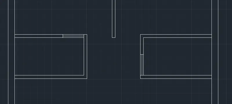
- Using reference lines and trim command, the doorway of 2’6” is provided for bathroom 1 in the north wall near the east wall and for bathroom 2 in the west wall near the south wall.
-
-
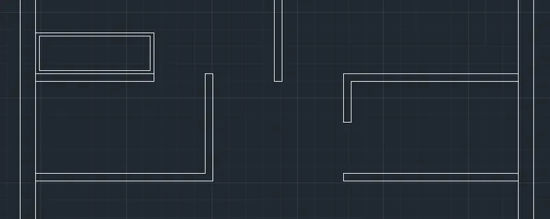
- A cupboard of dimension 5’9” x 2’ is provided in the bedrooms.
-
-
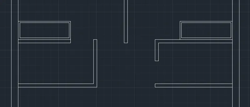
- Using offset and fillet (Radius 0) command, A kitchen slab of 2’ is provided in the east and south wall of the kitchen.
-
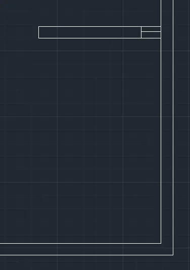
- The entrance window is provided at a distance of 1’3” from the east wall. Using line command, reference lines are drawn.
- Then draw a window of 6’ from the reference line and trim the reference lines.
-
-
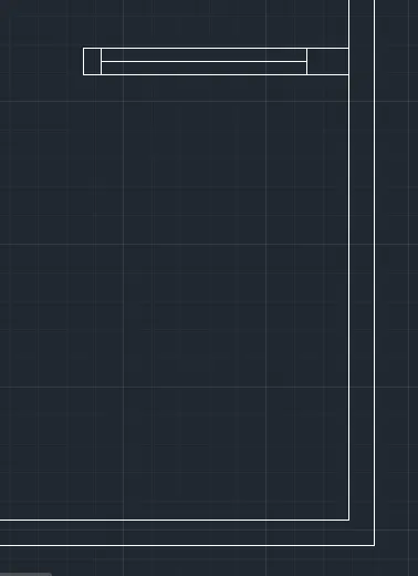
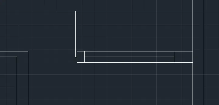
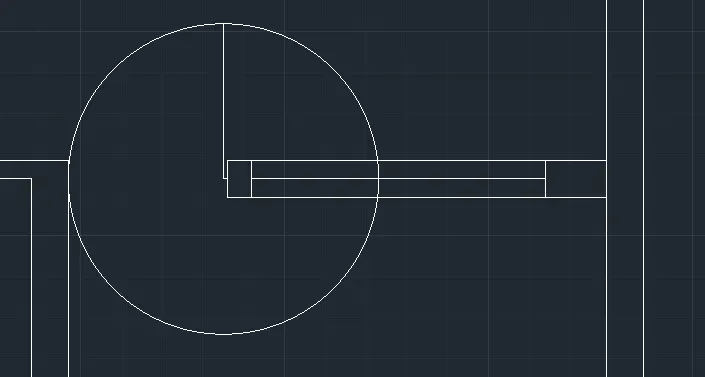
- Using commands line and circle, the entrance door is provided having a doorway of 3’3”.
-
-
-
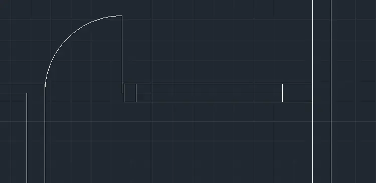
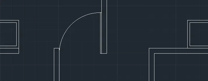
- Using commands line and circle, the bedroom doors are provided for the doorway of 3’.
-
-
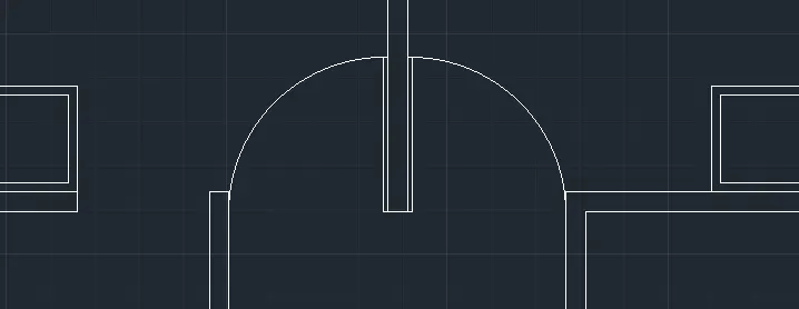
- Using commands line and circle, the bathroom doors are provided having a doorway of 2’6”.
-
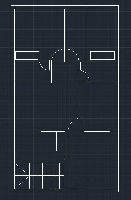
- Using text command, the names for different rooms are mentioned.
-
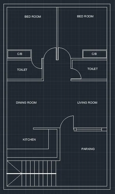
- Using line and trim command, the entrance is provided in the south wall.
-
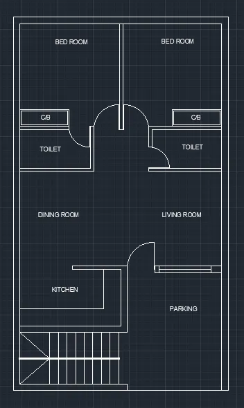
RESULT:
2.
AIM:
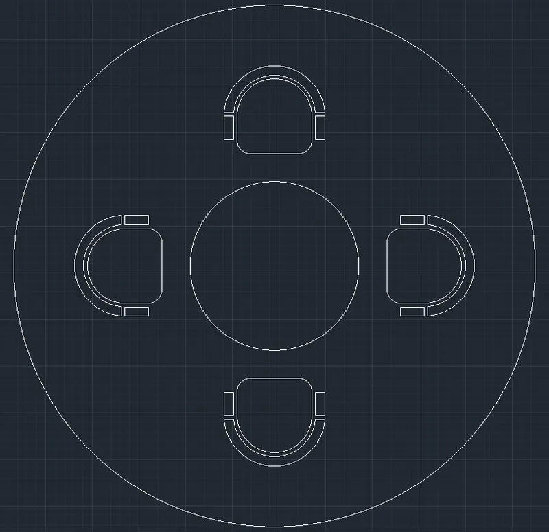
To sketch the layout of an outdoor canopy as shown in figure, explain the procedure in detail and obtain the final result.
INTRODUCTION:
AutoCAD is a computer aided design software and drafting software application.
In this week by completing diagram 1 (Residence plan), I learned how to draw a layout of a Residence, using various commands like units, limits, zoom, Xline, offset, fillet, circle, lineweight, erase/trim, copy, mirror, texts.
By completing diagram 2 (outdoor canopy), I have learnt to create objects on assuming dimensions which would fit the area perfectly.
By completing diagram 3 (toilets and utility room), I have used the “layers functions” where I created separate layers for outer walls, inner walls, doors, windows and ventilation, texts.
I have explained the detailed step by step procedure.
PROCEDURE:
- Open AutoCAD software
- Choose Decimal and start from scratch
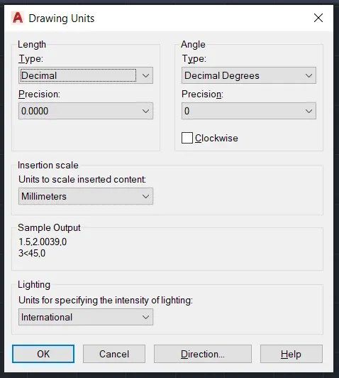
- Set the units to decimal and select ok
- Ensure the dynamic input is off.
- Specify the limits as lower left corner (0,0) and upper right corner (1000,1000)
- “Object snap<select all<ok”
-
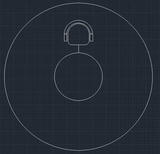
- With the same center point, draw 2 circles of radius 452 and radius 1398.
-
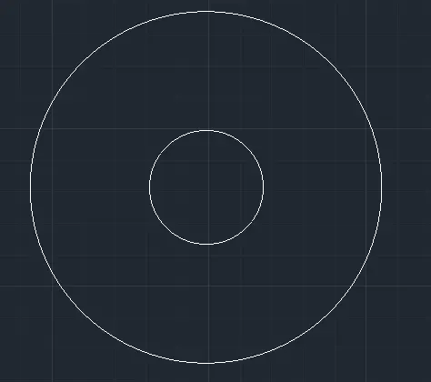
- With object snap on, draw a reference line of length 150 towards north from the top quadrant of the inner circle.
-
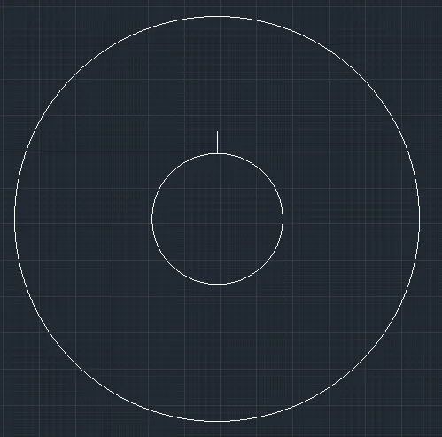
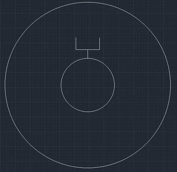
- From the endpoint of the reference line, draw a line of 200 towards right and a line of 200 towards left, totally it makes a length of 400 horizontally.
- And from both the ends of horizontal line, draw a line of 200 vertically.
-
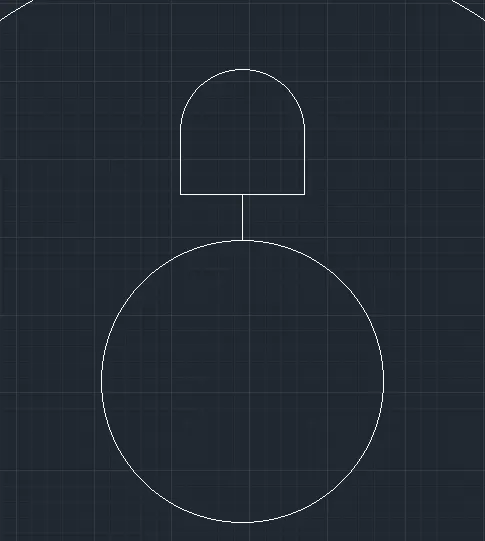
- Now, using fillet command join the two vertical lines.
-
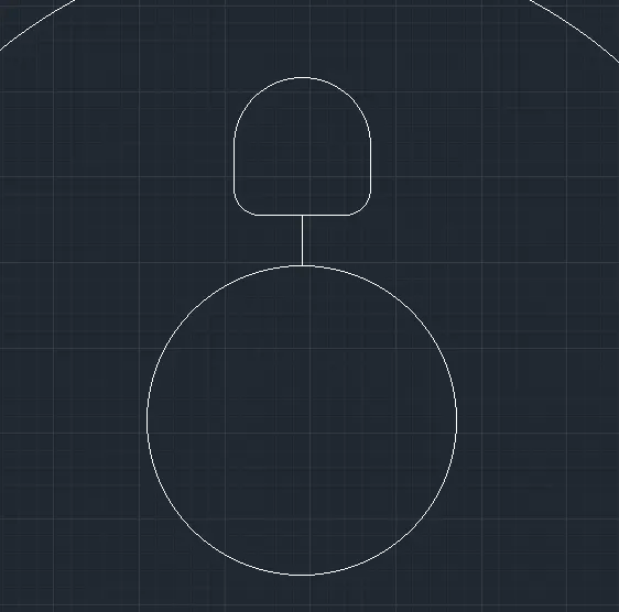
- Using fillet command, input (Radius 75) fillet the two bottom corners.
-
- Using offset command, offset the vertical lines and top bigger fillet to a distance of 20 towards outside.
-
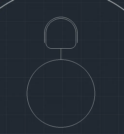
- Again, using offset command, offset the previous one (the vertical lines and top bigger fillet) to a distance of 50 towards outside.
-
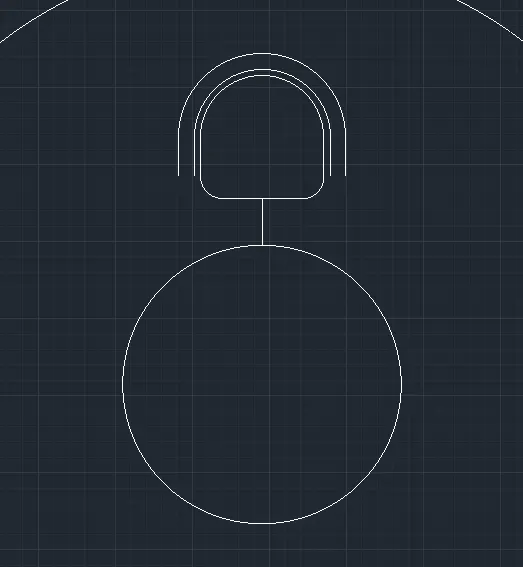
- Using line command, join the ends of vertical lines horizontally on both sides.
-
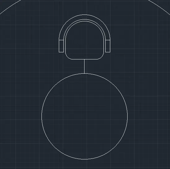
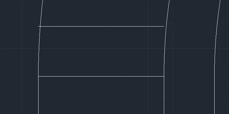
- Offset the top horizontal line to a distance of 20 on both sides.
-
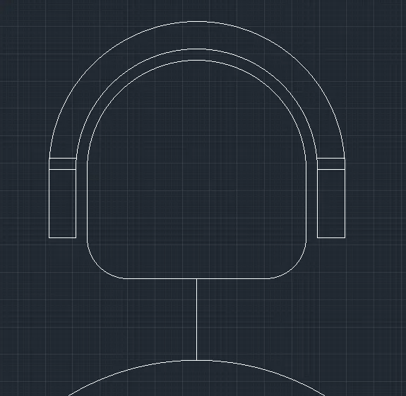
- Extend the line, so that it joins the curve.
-
-
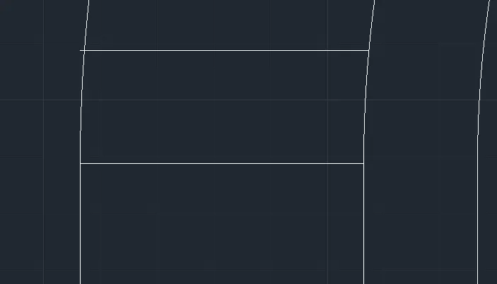
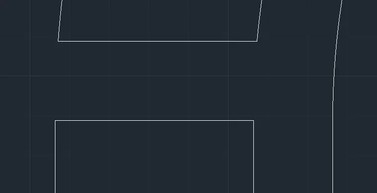
- Trim the lines, to finish the gap.
-
-
-
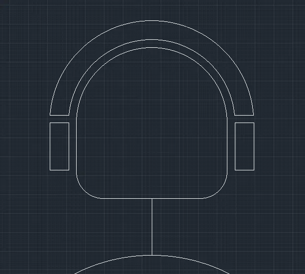
- Provide reference lines of length 150 from other 3 quadrants and copy the seating diagram 3 times to place it there.
-
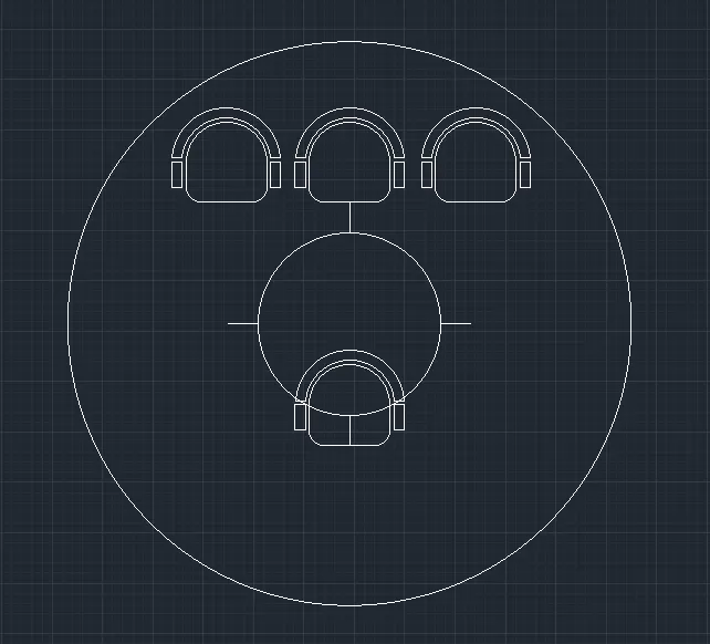
- Move the seating diagrams taking the midpoint of the large horizontal line as basepoint and place it at the end of each reference lines.
-
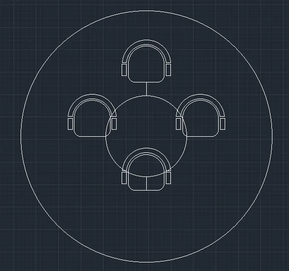
- Using rotate command, taking midpoint of the large horizontal line as basepoint, Rotate the seating diagrams accordingly, so that it replicates the first one which was created before.
-
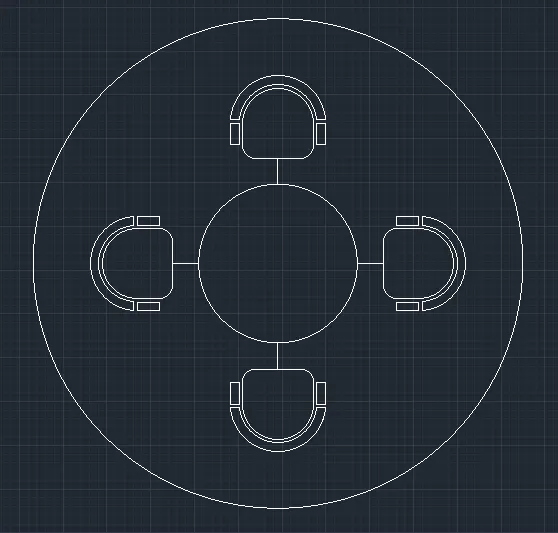
- Trim the reference lines to complete the drawing.
-
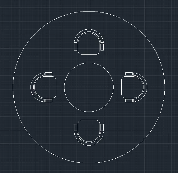
RESULT:
3.
AIM:
To sketch the layout of toilet and utilities room as shown in figure, explain the procedure in detail and obtain the final result.
INTRODUCTION:
AutoCAD is a computer aided design software and drafting software application.
In this week by completing diagram 1 (Residence plan), I learned how to draw a layout of a Residence, using various commands like units, limits, zoom, Xline, offset, fillet, circle, lineweight, erase/trim, copy, mirror, texts.
By completing diagram 2 (outdoor canopy), I have learnt to create objects on assuming dimensions which would fit the area perfectly.
By completing diagram 3 (toilets and utility room), I have used the “layers functions” where I created separate layers for outer walls, inner walls, doors, windows and ventilation, texts.
I have explained the detailed step by step procedure.
PROCEDURE:
- Open AutoCAD software
- Choose Decimal and start from scratch
- Set the units to decimal and select ok
- Ensure the dynamic input is off.
- Specify the limits as lower left corner (0,0) and upper right corner (10000,10000)
- “Object snap<select all<ok”
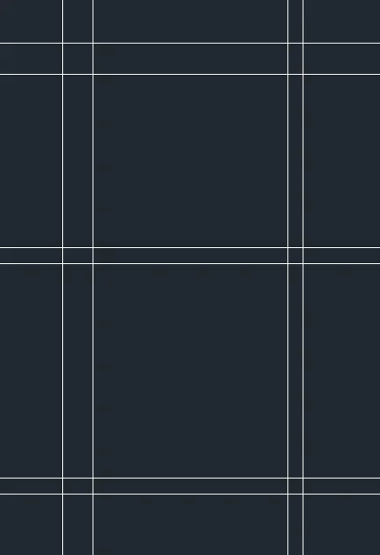
- Using command Xline(vertical), draw 2 lines at a distance of 1900
- Using command Xline (horizontal), draw 2 lines at a distance of 3950.
- Using offset command, offset the left vertical line to 300 towards outside and the right vertical line to 150 towards outside.
- Using offset command, offset the top horizontal line to 300 towards outside and the bottom horizontal line to 150 towards outside.
- Using offset command, offset the bottom horizontal line (excluding wall thickness) to 2100 towards inside and again offset the previous line to 150.
-
- Using fillet command, keeping (radius 0) join the outer lines and inner lines.
-
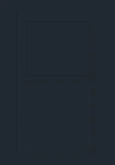
- Given the dimensions, 402 x 201 and 150mm thickness, it is drawn using line command.
-
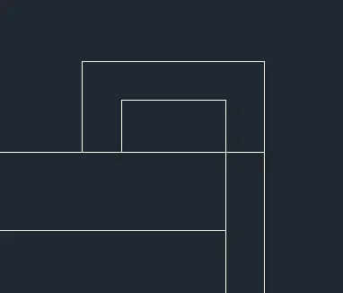
- Assume the wall extension near the door is 100mm and the door of 828mm starts from there.
- Using reference lines and trim command, the doorway of 828mm is provided.
-
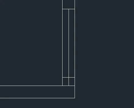
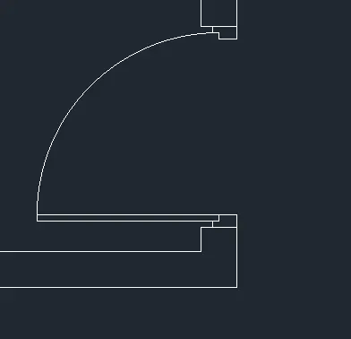
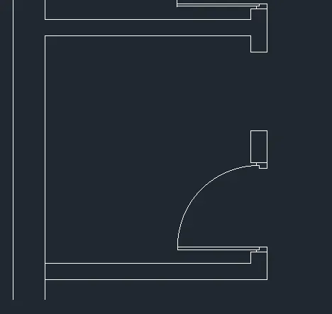
- Using line command, start from the right corner, go 50mm up continue 75mm to the left continue 25mm down continue 25mm left and then continue down to join the wall. Repeat with same lengths to finish on the other side.
-
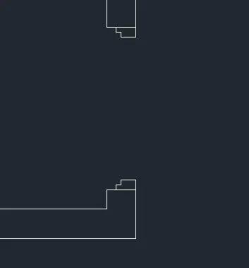
- Using line command, draw 728mm length 25mm thick door to fit in the corner.
-
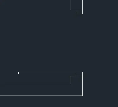
- Using circle command, draw a circle with joist of door as center point and expand it so that one of quadrant touches the other corner.
- Now using trim command, trim the other arcs to from a door swing.
-
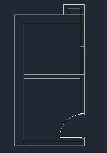
- Repeat the same procedure for the toilet room door also and here the doorway is 832mm.
- Assume the wall extension near the door is 100mm and the door of 832mm starts from there.
- Using reference lines and trim command, the doorway of 832mm is provided.
-
-
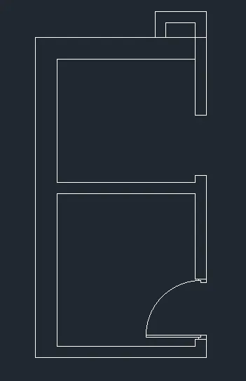
- Using line command, start from the right corner, go 50mm up continue 75mm to the left continue 25mm down continue 25mm left and then continue down to join the wall.
-
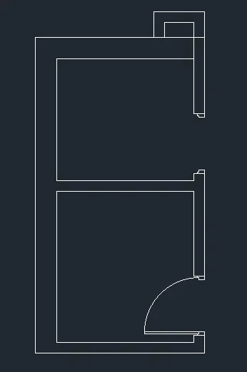
- Using line command, draw 732mm length 25mm thick door to fit in the corner.
- Using circle command, draw a circle with joist of door as center point and expand it so that one of quadrant touches the other corner.
-
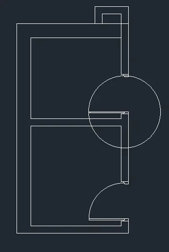
- Now using trim command, trim the other arcs to from a door swing.
-
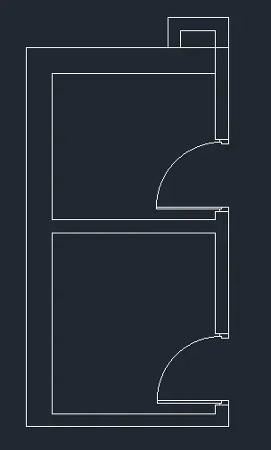
- Using line and trim command, the outer walls are finished correct.
-
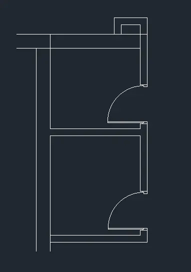
- Assume the window is at a distance of 150mm from the partition wall.
- Using line command, the reference lines are drawn to complete a window of 728mm.
-
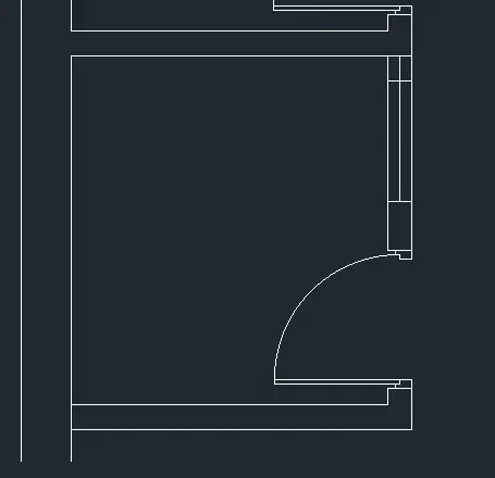
- After 728mm line is drawn and closed, trim the reference lines to get window spacing.
-
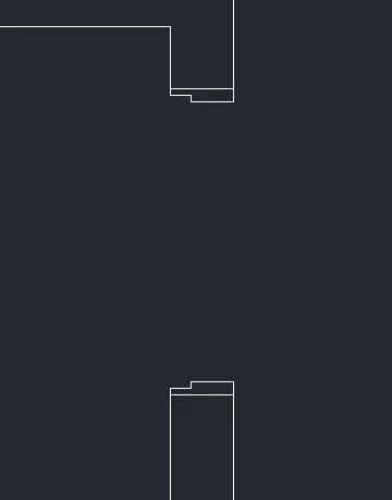
- Using line command, start from the right corner, go 30mm up continue 100mm to the left continue 15mm down continue 50mm left and then continue down to join the wall. Repeat with same lengths to finish on the other side.
-
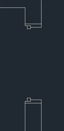
- Using line command, a small square of 30mm sides is drawn in the L-corner on both sides.
-
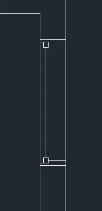
- Using line command, join the outer wall lines and the small squares to each other in the middle.
-
-

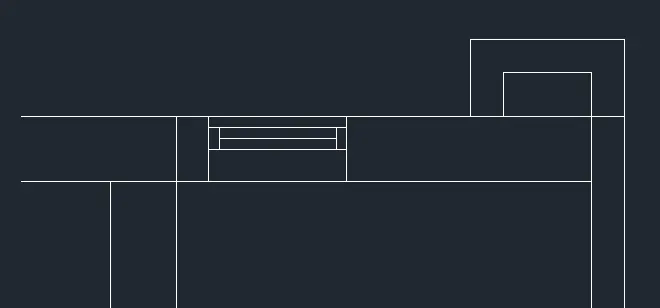
- Assume the ventilation is at a distance of 150mm from the 300mm wall.
- Using line command, the reference lines are drawn to complete a ventilation of 631mm.
- After 631mm line is drawn and closed, trim the reference lines to get window spacing.
- Using line command, draw 50mm x 100mm rectangles on both sides from midpoint of the line and join the rectangles in the outer corners and in the middle to complete the ventilation.
-
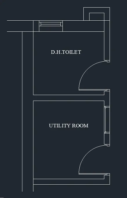
- Using text, mention the room names.
-
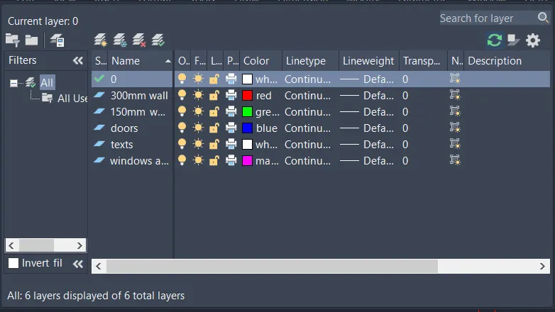
- Go to layer properties < create 5 new layers < name them as 300mm wall, 150mm wall, doors, texts and (windows & ventilation).
- Assign colors to each layer as red, green, blue, white and magenta.
-
- Now, select all the 300m walls in the drawing and select the layer created for it.
-
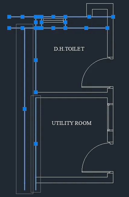
- As result, the 300mm walls are displayed red because the layer has been changed and red is the color assigned to that layer.
-
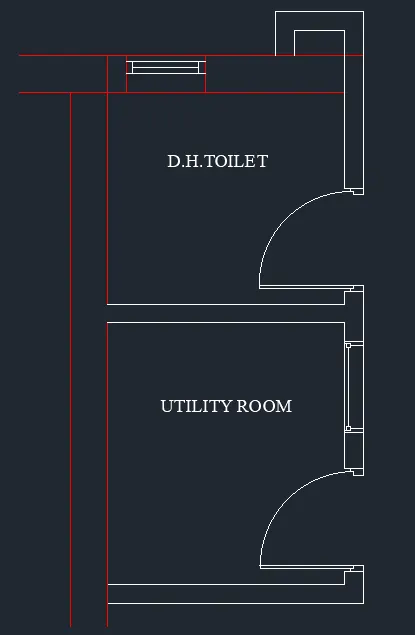
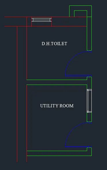
- Select all the 150mm thickness wall and select the 150mm wall layer in the layer properties, so that it changes layer and turns to the color green.
- Select all the doors and select the doors layer in the layer properties, so that it changes layer and turns to the color blue.
-
- Select the (W9 and V2) and select the (windows & ventilation) layer in the layer properties, so that it changes layer and turns to the color magenta.
-
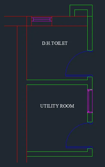
RESULT: