Drafting of various geometries using Chamfer, Fillet tool in AutoCad
CHALLENGE WEEK - 3
AutoCADD Essential
Question no.1:
- AIM:
- To draw a drawing using decimal units.
- The diagram to be drawn using line tool in AutoCADD software.
- Procedure:
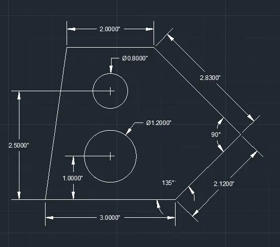
- The value to be used to draw the drawing is in meters, hence change the units in the template in autocadd to meters.
- Pick the line tool.
- Draw a line for 3m
- Then a line for 2.12m at 45 degree.
- Then a line 2.83 at 90degree to the line drawn before.
- Draw a line of 2m towards 180degree.
- Now a line to close the drawing to the starting point.
- Pick circle set point at 1.5,1 m and draw a circle for 1.2m dia.
- Then a oint of 1.5, 2.5 and a circle of 0.8m dia.
- And thus desired diagram is got
- RESULT:
- The drawing using decimal units was drawn.
- The drawing contains the dimension values.
- The drawing was completed using line tool.
Question no.2:
- AIM:
- To draw a drawing using Architectural units.
- The diagram to be drawn using line tool in AutoCADD software.
- Procedure:
- Pick the line tool.
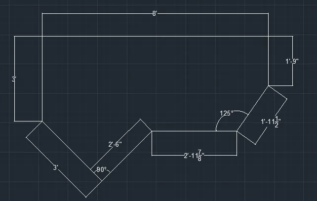
- Draw a line for 8'
- Then a line for 2'5" at 270 degree.
- Then a line 3' at 315 degree to the line drawn before.
- Draw a line of 2'6" 90degree to the line drwan before.
- Then to the end of 8' line an another line of 1'9" at 270 degree.
- Now a line of 2'10" at 25 degree.
- And finally join the line to the left line before.
- And thus desired diagram is got
- RESULT:
- The drawing using Architectural units was drawn.
- The drawing contains the dimension values.
- The drawing was completed using line tool.
Question no.3:
- AIM:
- To draw a drawing using Engineering units.
- The diagram to be drawn using line tool in AutoCADD software.
- Procedure:
- Pick the line tool.
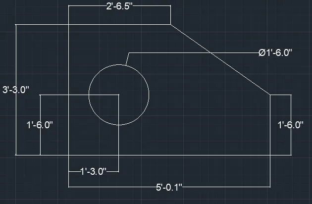
- Draw a line for 5'0.1"
- Then a line for 3'3.0" at 90 degree.
- Then a line 2'6.5" at 0 degree.
- Draw a line of 2'6" 90degree to the line drwan before.
- Then to the end of 5'0.1" line an another line of 1'6.0" at 90 degree.
- And finally join the line to the left line before.
- Now a circle at 1'3",1'6" of dia 1'6".
- And thus desired diagram is got.
- RESULT:
- The drawing using Engineering units was drawn.
- The drawing contains the dimension values.
- The drawing was completed using line tool.
Question no.4:
- AIM:
- To draw a drawing using decimal unit type.
- The diagram to be drawn using line tool in AutoCADD software.
- Procedure:
- Pick the line tool.
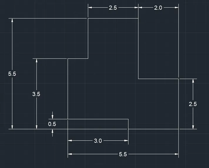
- Draw a line for 5.5m
- Then a line for 2.5m at 90 degree.
- Then a line 2m at 180 degree.
- Draw a line of 3m 90degree to the line drwan before.
- Then an another line of 2.5m at 180 degree.
- Then a line 2m at 270 degree.
- Then a line 1m at 180 degree.
- Then a line 3m at 270 degree.
- Then a line 3m at 0 degree.
- And finally join the line to the left line before.
- And thus desired diagram is got.
- RESULT:
- The drawing using Decimal units was drawn.
- The drawing contains the dimension values.
- The drawing was completed using line tool.
Question no.5:
- AIM:
- To draw a drawing using decimal unit type.
- The diagram to be drawn using line tool in AutoCADD software.
- Procedure:
- Pick the line tool.
- Draw a line for 11.5m
- Then a line for 6m at 90 degree.
- Then a line 11.5m at 180 degree.
- Give close command.
- Then offset the lines on the both sides to3m inside
- Now take circle at point 1.5,3
- And draw a circle of dia 1 and 2m forom same point
- Now take circle at point 10,3
- And draw a circle of dia 1 and 2m forom same point
- Now take circle at point 5.75,3
- And draw a circle of dia 3m
- And thus desired diagram is got.
- RESULT:
- The drawing using Decimal units was drawn.
- The drawing contains the dimension values.
- The drawing was completed using line tool.
Question no.6:
- AIM:
- To draw a drawing using decimal unit type.
- The diagram to be drawn using line tool in AutoCADD software.
- Procedure:
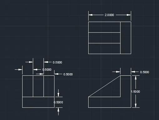
- Pick the line tool.
- Draw a line for 2m
- Then a line for 1.5m at 270 degree.
- Then a line 2m at 180 degree.
- Give close command.
- Then offset the line at the right corner to 0.5m
- Then offset the line at the top to 0.5m below
- Now we got a top view
- Then take reference lines from the image drawn before towards down
- Then draw a line of 1.5m at 270 degree
- Then an another line of 2m at 180 degree.
- Then a line 0.5m at 90 degree.
- Then a line 1.5m at 0 degree.
- Give close command.
- Now we got a side view
- Then take reference lines from the image drawn before towards left
- Then draw a line of 1.5m at 180 degree
- Then an another line of 2m at 90 degree.
- Then a line 1.5m at 0 degree.
- Give close command.
- Noew off set the bottom line to 0.5 above.
- Then offset the side line to 0.5 2 times
- Now we got a Front view
- And thus desired diagram is got.
- RESULT:
- The drawing using Decimal units was drawn.
- The drawing contains the dimension values.
- The drawing was completed using line tool.
Question no.7:
- AIM:
- To draw a drawing using decimal units.
- The diagram to be drawn using line tool in AutoCADD software.
- Procedure:
- The value to be used to draw the drawing is in meters, hence change the units in the template in autocadd to meters.
- Pick the line tool.
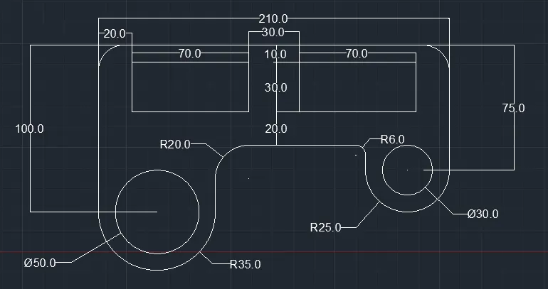
- Draw a line for 210mm
- Then a line for 75m at 270degree.
- Then a line 50mm at 180 degree to the line drawn before.
- Then to the other end of the 210mm line
- Draw a line of 100mm at 270 degrees.
- Now a line of 70mm at 0 degrees.
- Now pick the centre of 210mm line and mark a point 60mm below.
- And extend the line on both sides to connect the both unfinished lines.
- Noe take fillet option of 15 radius and choose top tow edges
- And 20mm radius and 6mm radis at below lines
- Now a circle at the mid point of the 70mm adn 50mm lines of dia 50 and 30 respectively.
- And a semicircle the the end of the two lines.
- And thus desired diagram is got
- RESULT:
- The drawing using decimal units was drawn.
- The drawing contains the dimension values.
- The drawing was completed using line tool.
Question no.8:
- AIM:
- To draw a drawing using decimal units.
- The diagram to be drawn using line tool in AutoCADD software.
- Procedure:
- The value to be used to draw the drawing is in meters, hence change the units in the template in autocadd to meters.
- Pick the line tool.
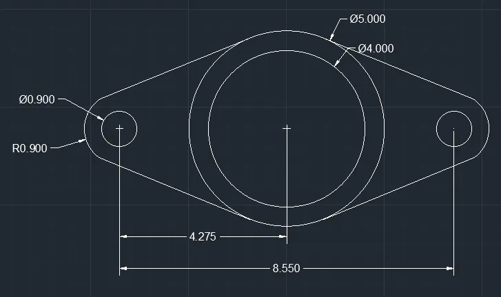
- Draw two circles of dia 5 and 4 from a same point.
- Now two small circles on the either sides of the big circles of dia 0.9m
- And the cicrle of 0.9 radius to be drawn the small circle center.
- Now take tangent line to connect the big circle.
- Now trim all the other lines.
- And thus desired diagram is got
- RESULT:
- The drawing using decimal units was drawn.
- The drawing contains the dimension values.
- The drawing was completed using line tool.
Question no.9:
- AIM:
- To draw a drawing using Engineeering unit type.
- The diagram to be drawn using line tool in AutoCADD software.
- Procedure:
- Pick the cicle tool.
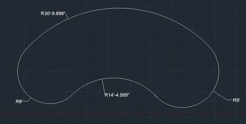
- Draw a circles of 9' and 8' radius
- Pick start end radius type of arc.
- Touch the tangets of the circleon both sides
- The arcs of radius, 41'8" on the top and 20'10" on bottom.
- Now trim the remaining arcs of circles
- And thus desired diagram is got.
- RESULT:
- The drawing using Engineering units was drawn.
- The drawing contains the dimension values.
- The drawing was completed using line tool.
Question no.10:
- AIM:
- To draw a drawing using decimal units.
- The diagram to be drawn using line tool in AutoCADD software.
- Procedure:
- The value to be used to draw the drawing is in meters, hence change the units in the template in autocadd to meters.
- Pick the line tool.
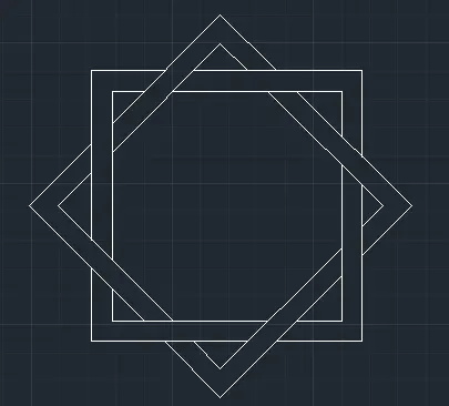
- Draw a square of 4m
- offset the sqaure to 0.5m
- Now copy the drawn square.
- Rotate the copied square to 45 degree.
- Bring the rotated sqare to the mid of the main square.
- Now trim the alternative lines to make it look like it passes through each other.
- And thus desired diagram is got
- RESULT:
- The drawing using decimal units was drawn.
- The drawing contains the dimension values.
- The drawing was completed using line tool.
Question no.11:
- AIM:
- To draw a drawing using Engineering units.
- The diagram to be drawn using line tool in AutoCADD software.
- Procedure:
- Pick the line tool.
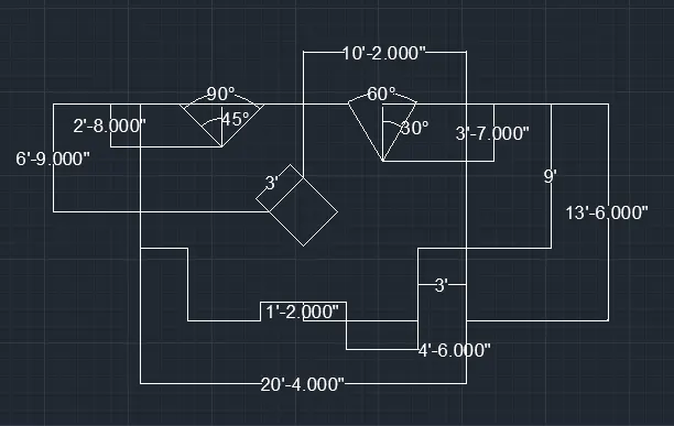
- Draw a line for 6'9" at 90
- Then a line for 20'4" at 0 degree.
- Then a line 3' at 180degree.
- Draw a line of 4'6" 2700degree to the line drwan before.
- Then to the end of 4'6" line at 180 degree.
- Then a line of 1'2" at 90 degrees.
- Then close the line
- Now a draw a V shape at the above line to the centre of the below line
- One V shape of 45 and 2'8"
- Another V shape of 30 degrees of 3'7".
- Now a cube of 3' at the middle of the draiwing.
- And thus desired diagram is got.
- RESULT:
- The drawing using Engineering units was drawn.
- The drawing contains the dimension values.
- The drawing was completed using line tool.