Creation of geometries by Coordinate system methods using AutoCad
CHALLENGE WEEK - 1
AutoCADD Essential
Question no.1:
- Aim:
- To Create a geometrical shape using Absolute coordinate system and Relative coordinate system in AutoCADD software.
- To Create geometries using the line tool.
- Procedure:
- Absolute Coordinate system:
- Initially after opening the AutoCadd software check the drafting settings(DS) that is in dynamic input in enable pointer input the settings is in Absolute coordinates.
- Then starting the drawing check for the origin point.
- In this drawing the origin point is given as (2,1) - (X,Y).
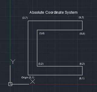
- First displacement in absolute coordinate (2,7)
- The absolute coordinate first point by (8,7)
- The absolute coordinate next point by (8,6)
- The absolute coordinate next point by (3,6)
- The absolute coordinate next point by (3,2)
- The absolute coordinate next point by (8,2)
- The absolute coordinate next point by (8,1)
- The close command to close the drawing to the origin.
- Drawing:
- Relative Rectangular coordinate system:
- The origin point is given as (2,1) - (X,Y)
- The drawing is raised using the relative rectangular system.
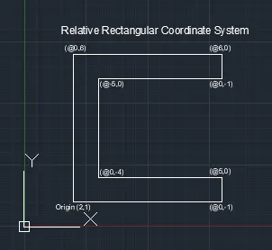
- The First point is drawn by (@0,6)
- Then the next point by (@6,0)
- Then the next point by (@0,-1)
- Then the next point by (@-5,0)
- Then the next point by (@0,-4)
- Then the next point by (@5,0)
- Then the next point by (@0,-1)
- Then close command to close the drawing.
- Drawing:
- Relative Polar coordinate system:
- The origin point is given as (2,1) - (X,Y)
- The drawing is raised using the relative Polar system.
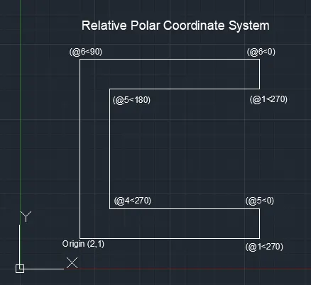
- The First point is drawn by (@6<90)
- Then the next point by (@6<0)
- Then the next point by (@1<270)
- Then the next point by (@5<180)
- Then the next point by (@4<270)
- Then the next point by (@5<0)
- Then the next point by (@1<270)
- Then close command to close the drawing.
- Drawing:
- Result:
- The given drawing was drawn with all coordinate system.
- The line tool is used
- The imperial template with units in inches and feets was used.
- The drawing was successfully obtained in all coordinate system methods.
Question no.2:
- Aim:
- To Create a geometrical shape using Absolute coordinate system and Relative coordinate system in AutoCADD software.
- To Create geometries using the line tool.
- Procedure:
- Absolute Coordinate system:
- Initially after opening the AutoCadd software check the drafting settings(DS) that is in dynamic input in enable pointer input the settings is in Absolute coordinates.
- Then starting the drawing check for the origin point.
- In this drawing the origin point is given as (2,1) - (X,Y).
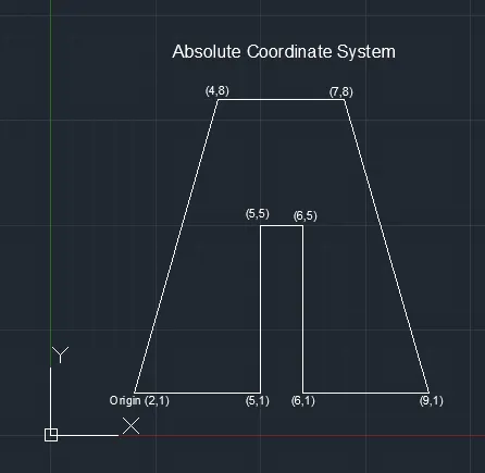
- First displacement in absolute coordinate (4,8)
- The absolute coordinate first point by (7,8)
- The absolute coordinate next point by (9,1)
- The absolute coordinate next point by (6,1)
- The absolute coordinate next point by (6,5)
- The absolute coordinate next point by (5,5)
- The absolute coordinate next point by (5,1)
- The close command to close the drawing to the origin.
- Drawing:
- Relative Rectangular coordinate system:
- The origin point is given as (2,1) - (X,Y)
- The drawing is raised using the relative rectangular system.
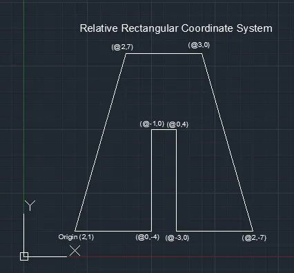
- The First point is drawn by (@2,7)
- Then the next point by (@3,0)
- Then the next point by (@2,-7)
- Then the next point by (@-3,0)
- Then the next point by (@0,4)
- Then the next point by (@-1,0)
- Then the next point by (@0,-4)
- Then close command to close the drawing.
- Drawing:
- Relative Polar coordinate system:
- In this drawing, the drawing cannot be drawn using Relative polar coordinate system as there are no angles mentioned.
- Relative polar coordinate needs angles for directing the line
- Result:
- The given drawing was drawn with Absolute and Relative Rectangular coordinate system.
- The line tool is used
- The imperial template with units in inches and feets was used.
- The drawing was successfully obtained in Absolute and Relative Rectangular coordinate system methods.
Question no.3:
- Aim:
- To Create a geometrical shape using Absolute coordinate system in AutoCADD software.
- To Create geometries using the line tool.
- Procedure:
- Absolute Coordinate system:
- Initially after opening the AutoCadd software check the drafting settings(DS) that is in dynamic input in enable pointer input the settings is in Absolute coordinates.
- Then starting the drawing check for the origin point.
- In this drawing the origin point is given as (2,1) - (X,Y).
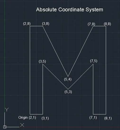
- First displacement in absolute coordinate (2,8)
- The absolute coordinate first point by (3,8)
- The absolute coordinate next point by (5,4)
- The absolute coordinate next point by (7,8)
- The absolute coordinate next point by (8,8)
- The absolute coordinate next point by (8,1)
- The absolute coordinate next point by (7,1)
- The absolute coordinate next point by (7,5)
- The absolute coordinate next point by (5,3)
- The absolute coordinate next point by (3,5)
- The absolute coordinate next point by (3,1)
- The close command to close the drawing to the origin.
- Drawing:
- Result:
- The given drawing was drawn with Absolute coordinate system.
- The line tool is used
- The imperial template with units in inches and feets was used.
- The drawing was successfully obtained in Absolute coordinate system methods.
Question no.4:
- Aim:
- To Create a geometrical shape using Relative polar coordinate system in AutoCADD software.
- To Create geometries using the line tool.
- Procedure:
- Relative Polar coordinate system:
- The origin point is given as (2,1) - (X,Y)
- The drawing is raised using the relative Polar system.
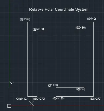
- The First point is drawn by (@8<90)
- Then the next point by (@7<0)
- Then the next point by (@8<270)
- Then the next point by (@4<180)
- Then the next point by (@1<90)
- Then the next point by (@3<0)
- Then the next point by (@6<90)
- Then the next point by (@5<180)
- Then the next point by (@7<270)
- Then close command to close the drawing.
- Drawing:
- Result:
- The given drawing was drawn with Relative polar coordinate system.
- The line tool is used
- The imperial template with units in inches and feets was used.
- The drawing was successfully obtained in Relative polar coordinate system methods.
Question no.5:
- Aim:
- To Create a geometrical shape using Absolute coordinate system in AutoCADD software.
- To Create geometries using the line tool.
- Procedure:
- Absolute Coordinate system:
- Initially after opening the AutoCadd software check the drafting settings(DS) that is in dynamic input in enable pointer input the settings is in Absolute coordinates.
- Then starting the drawing check for the origin point.
- In this drawing the origin point is given as (2,1) - (X,Y).
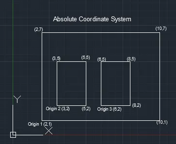
- First displacement in absolute coordinate (2,7)
- The absolute coordinate next point by (10,7)
- Then the drawing is closed using close command
- As it has another 2 drawing inside this, with other points as origin another origin has been considered
- Here the orogin point for the inside drawing 1 is taken as origin 2 (3,2) - (X,Y)
- The absolute coordinate next point by (3,5)
- The absolute coordinate next point by (5,5)
- The absolute coordinate next point by (5,2)
- Here the orogin point for the inside drawing 2 is taken as origin 3 (6,2) - (X,Y)
- The absolute coordinate next point by (6,5)
- The absolute coordinate next point by (8,5)
- The absolute coordinate next point by (8,2)
- The close command to close the drawing to the origin.
- The whole drawing containing two small boxes inside a single big box is drafted using absolute coordinate system.
- Drawing:
- Result:
- The given drawing was drawn with Absolute coordinate system.
- The line tool is used
- The imperial template with units in inches and feets was used.
- The whole drawing containing two small boxes inside a single big box is drafted using absolute coordinate system.
- The drawing was successfully obtained in Absolute coordinate system methods.
Question no.6:
- Aim:
- To Create a geometrical shape using Relative Rectangular coordinate system in AutoCADD software.
- To Create geometries using the line tool.
- Procedure:
- Relative Rectangular coordinate system:
- The origin point is given as (0,0) - (X,Y)
- The drawing is raised using the relative rectangular system.
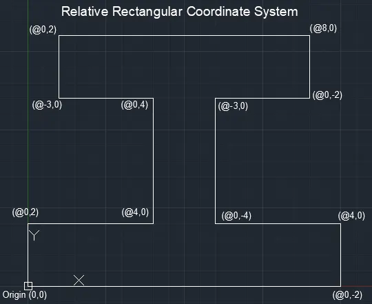
- The First point is drawn by (@0,2)
- Then the next point by (@4,0)
- Then the next point by (@0,4)
- Then the next point by (@-3,0)
- Then the next point by (@0,2)
- Then the next point by (@8,0)
- Then the next point by (@0,-2)
- Then the next point by (@-3,0)
- Then the next point by (@0,-4)
- Then the next point by (@4,0)
- Then close command to close the drawing.
- Drawing:
- Result:
- The given drawing was drawn with Relative rectangular coordinate system.
- The line tool is used
- The imperial template with units in inches and feets was used.
- The drawing was successfully obtained in Relative rectangular coordinate system methods.
Question no.7:
- Aim:
- To Create a geometrical shape using Relative Rectangular coordinate system in AutoCADD software.
- To Create geometries using the line tool.
- Procedure:
- Relative Rectangular coordinate system:
- The origin point is given as (1,1) - (X,Y)
- The drawing is raised using the relative rectangular system.
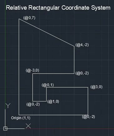
- The First point is drawn by (@0,7)
- Then the next point by (@4,-2)
- Then the next point by (@0,-2)
- Then the next point by (@-3,0)
- Then the next point by (@0,-2)
- Then the next point by (@1,0)
- Then the next point by (@0,-1)
- Then the next point by (@3,0)
- Then the next point by (@0,-2)
- Then close command to close the drawing.
- Drawing:
- Result:
- The given drawing was drawn with Relative rectangular coordinate system.
- The line tool is used
- The imperial template with units in inches and feets was used.
- The drawing was successfully obtained in Relative rectangular coordinate system methods.
Question no.8:
- Aim:
- To Create a geometrical shape using Relative polar coordinate system in AutoCADD software.
- To Create geometries using the line tool.
- Procedure:
- Relative Polar coordinate system:
- The origin point is given as (1,1) - (X,Y)
- The drawing is raised using the relative Polar system.
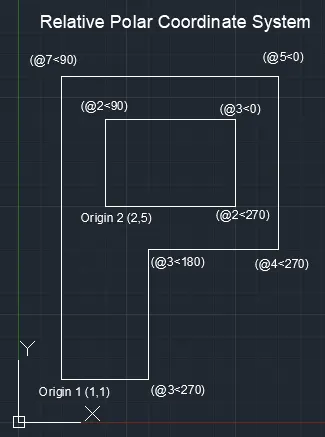
- The First point is drawn by (@7<90)
- Then the next point by (@5<0)
- Then the next point by (@4<270)
- Then the next point by (@3<180)
- Then the next point by (@3<270)
- Then the first drawing is closed with close command.
- As it has another 1 drawing inside this, with other points as origin another origin has been considered
- Here the orogin point for the inside drawing is taken as origin 2 (2,5) - (X,Y)
- Then the next point by (@2<90)
- Then the next point by (@3<0)
- Then the next point by (@2<270)
- Then close command to close the drawing.
- The whole drawing containing one small box inside a "P" shape is drafted using Relative rectangular coordinate system.
- Drawing:
- Result:
- The given drawing was drawn with Relative polar coordinate system.
- The line tool is used
- The imperial template with units in inches and feets was used.
- The whole drawing containing one small box inside a "P" shape is drafted using Relative rectangular coordinate system.
- The drawing was successfully obtained in Relative polar coordinate system methods.
Question no.9:
- Aim:
- To Create a geometrical shape using Relative polar coordinate system in AutoCADD software.
- To Create geometries using the line tool.
- Procedure:
- Relative Polar coordinate system:
- The origin point is given as (0,0) - (X,Y)
- The drawing is raised using the relative Polar system.
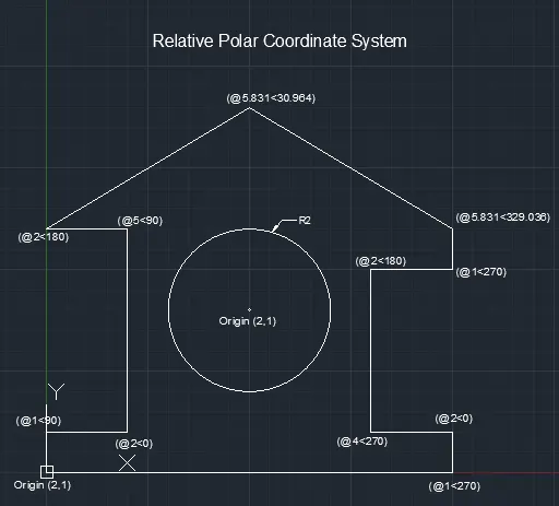
- The First point is drawn by (@1<90)
- Then the next point by (@2<0)
- Then the next point by (@5<90)
- Then the next point by (@2<180)
- Then the next point by (@5.831<30.964)
- Then the next point by (@5.831<329.036)
- Then the next point by (@1<270)
- Then the next point by (@2<180)
- Then the next point by (@4<270)
- Then the next point by (@2<0)
- Then the next point by (@1<270)
- Then close command to close the drawing.
- And there is a circle give inside the profile wood drawing.
- The origin of the circle is mentiones as (2,1) hence use as it is.
- And the radius is given as 2 as mentioned in the drawing.
- Drawing:
- Result:
- The given drawing was drawn with Relative polar coordinate system.
- The line tool is used
- The imperial template with units in inches and feets was used.
- The drawing was successfully obtained in Relative polar coordinate system methods.
Question no.10:
- Aim:
- To Create a geometrical shape using Relative Rectangular coordinate system in AutoCADD software.
- To Create geometries using the line tool.
- Procedure:
- Relative Rectangular coordinate system:
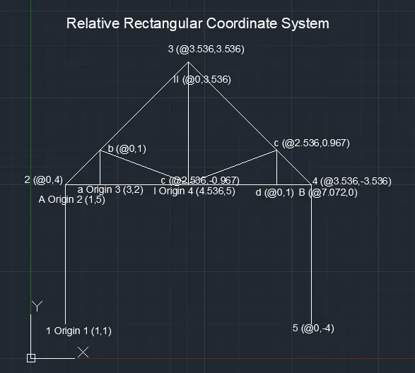
- Here in this drawing there is a queen truss to be drawn which needs 4 origin points to be considered
- Hence 4 origin points as mentioned below:
- 1 origin 1(1,1) for the outer structure of the truss
- A origin 2(1,5) for the horizontal straight line carrying the truss
- a origin 3(3,2) for the truss structure inside.
- I origin 4(4.536,5) for the vertical line
- The origin point is given as 1 origin 1(1,1) - (X,Y)
- The drawing is raised using the relative rectangular system.
- The First point is drawn by (@0,4)
- Then the next point by (@3.536,3.536)
- Then the next point by (@3.536,-3.536)
- Then the next point by (@0,-4)
- Then considering the next origin for the straight line carrying the truss
- The origin for the truss is considered as A origin 2(1,5)
- Then the next point by (@7.072,0)
- Then considering the next origin for the truss
- The origin for the truss is considered as a origin 3(3,2)
- Then the next point by (@0,1)
- Then the next point by (@2.536,-0.967)
- Then the next point by (@2.536,0.967)
- Then the next point by (@0,1)
- Then considering the next origin for the straight line vertical to the truss
- The origin for the truss is considered as I origin 4(4.536,5)
- Then the next point by (@0,3.536)
- The whole drawing containing queen post truss which has a truss structure shape inside it was drawn using Relative rectangular coordinate.
- Drawing:
- Result:
- The given drawing was drawn with Relative rectangular coordinate system.
- The line tool is used
- The imperial template with units in inches and feets was used.
- The whole drawing containing a queen post truss which has a truss structure shape inside it was drawn using Relative rectangular coordinate.
- The drawing was successfully obtained in Relative rectangular coordinate system methods.
Question no.11:
- Aim:
- To Create a geometrical shape using Relative Rectangular coordinate system in AutoCADD software.
- To Create geometries using the line tool.
- Procedure:
- Relative Rectangular coordinate system:
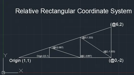
- The origin point is given as (1,1) - (X,Y)
- The drawing is raised using the relative rectangular system.
- The First point is drawn by (@6,2)
- Then the next point by (@0,-2)
- Then the colse command is given to close the first drawing.
- A truss is given to be drawn inside the main drawing.
- The origin for the truss is considered as origin 2 (3,1)
- Then the next point by (@0,0.667)
- Then the next point by (@2,-0.667)
- Then the next point by (@0,1333)
- Then the next point by (@2,-1333)
- The whole drawing containing one triangle shape which has a truss structure shape inside it was drawn using Relative rectangular coordinate.
- Drawing:
- Result:
- The given drawing was drawn with Relative rectangular coordinate system.
- The line tool is used
- The imperial template with units in inches and feets was used.
- The whole drawing containing one triangle shape which has a truss structure shape inside it was drawn using Relative rectangular coordinate.
- The drawing was successfully obtained in Relative rectangular coordinate system methods.