Drafting of various geometries using Chamfer, Fillet tool in AutoCad
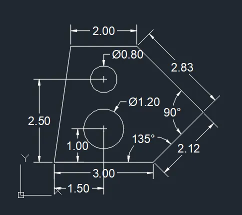
Q1: Aim: To draw the geometry using the direct distance entry method, and illustrate the procedure involved.
Procedure:
- Create a new drawing from the dropdown menu
- Select the imperial system and decimal units
- Change the insertion scale to meters
- Type L to activate line tool
- Type the first point coordinate as (1,1)
- Activate orthomode (F8)
- Position the cursor and enter the distance 3
- Deactivate orthomode (F8)
- Enter the next point @2.12<45
- Enter the next point @2.83<135
- Activate orthomode (F8)
- Position the cursor and enter the distance 2
- Select the close option from the command bar
- Type C to activate circle tool
- Enter the coordinates of the centre of the circle (2.5,2)
- Select the diameter option in the command bar
- Enter the diameter of circle 1.2
- Type C to activate circle tool
- Enter the coordinates of the centre of the circle (2.5,3.5)
- Select the diameter option in the command bar
- Enter the diameter of the circle 0.8
- Save the drawing
Q2: Aim: To draw the geometry using the direct distance entry method, and illustrate the procedure involved.
Procedure:
- Create a new drawing from the dropdown menu
- Select the imperial system and architecture units
- Change the insertion scale to inches
- Type L to activate line tool
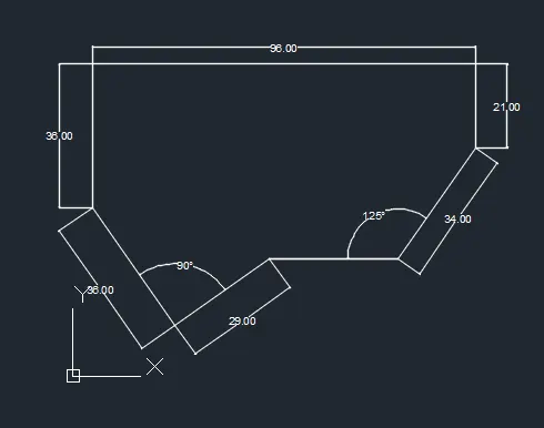
- Type the first point coordinate as (50,30)
- Enter the next point @2'6"<215
- Enter the next point @3'<125
- Activate orthomode (F8)
- Position the cursor and enter the distance of 3'
- Position the cursor and enter the distance of 8'
- Position the cursor and enter the distance of 1'9"
- Deactivate orthomode (F8)
- Enter the next point @2'10"<235
- Select the close option from the command bar
- Save the drawing
Q3: Aim: To draw the geometry using the direct distance entry method, and illustrate the procedure involved.
Procedure:
- Create a new drawing from the dropdown menu
- Select the imperial system and engineering units
- Change the insertion scale to inches
- Type L to activate line tool
- Enter the first coordinate (10,10)
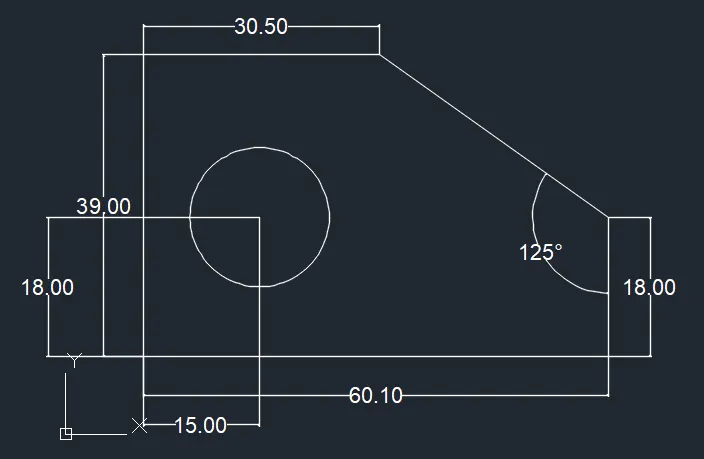
- Position the cursor and enter the distance of 30.5
- Position the cursor and enter the distance 39
- Position the cursor and enter the distance 60.1
- Position the cursor and enter the distance 18
- Select the close option from the command bar
- Type C to activate circle tool
- Enter the coordinates of the centre of the circle(25,28)
- Select the diameter option in the command bar
- Enter the diameter of the circle 18
- Save the drawing
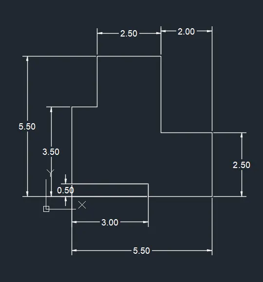
Q4: Aim: To draw the geometry using the direct distance entry method, and illustrate the procedure involved.
Procedure:
- Create a new drawing from the dropdown menu
- Select the imperial system and decimal units
- Change the insertion scale to meters
- Type L to activate line tool
- Enter the first coordinate (1,1)
- Position the cursor and enter the distance 3
- Position the cursor and enter the distance 0.5
- Position the cursor and enter the distance 2.5
- Position the cursor and enter the distance 2.5
- Position the cursor and enter the distance 2
- Position the cursor and enter the distance 3
- Position the cursor and enter the distance 2.5
- Position the cursor and enter the distance 2
- Position the cursor and enter the distance 1
- Select the close option from the command bar
- Save the drawing
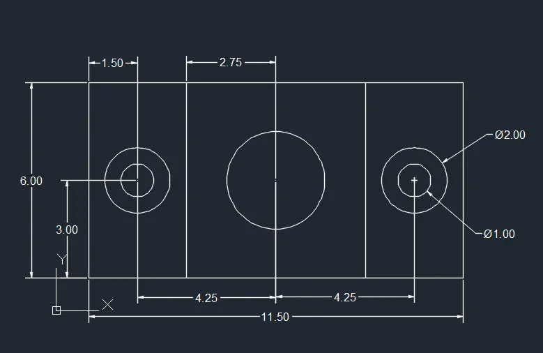
Q5: Aim: To draw the geometry using the direct distance entry method, and illustrate the procedure involved.
Procedure:
- Create a new drawing from the dropdown menu
- Select the imperial system and decimal units
- Change the insertion scale to meters
- Type L to activate line tool
- Enter the first coordinate (1,1)
- Position the cursor and enter the distance 11.5
- Position the cursor and enter the distance 6
- Position the cursor and enter the distance 11.5
- Select the close option from the command bar
- Type L to activate line tool
- Enter the first coordinate (4,1)
- Position the cursor and enter the distance 6
- Type O to activate offset
- Enter the offset distance 5.5
- Select the above line
- Specify the side of the offset
- Type C to activate circle tool
- Enter the coordinates of the centre of the circle(2.5,4)
- Select the diameter option in the command bar
- Enter the diameter of the circle 1
- Type C to activate circle tool
- Enter the coordinates of the centre of the circle(2.5,4)
- Select the diameter option in the command bar
- Enter the diameter of circle 2
- Type CO to activate copy tool
- Select above 2 circles and press enter
- Specify the basepoint as the centre of the circle
- Position the cursor and enter the distance 8.5
- Type C to activate circle tool
- Enter the coordinates of the centre of the circle(6.75,4)
- Select the diameter option in the command bar
- Enter the diameter of circle 3
- Save the drawing
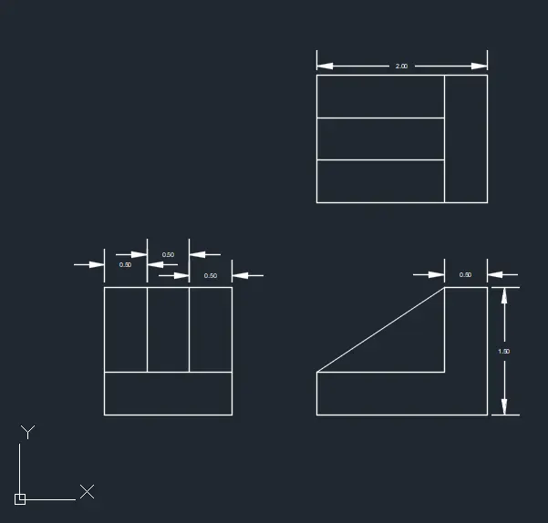
Q6: Aim: To draw the geometry using the direct distance entry method, and illustrate the procedure involved.
Procedure:
- Create a new drawing from the dropdown menu
- Select the imperial system and decimal units
- Change the insertion scale to meters
- Type L to activate line tool
- Activate orthomode (F8)
- Enter the first coordinate (1,1)
- Position the cursor and enter the distance 1.5
- Position the cursor and enter the distance1.5
- Position the cursor and enter the distance 1.5
- Select the close option from the command bar
- Type L to activate line tool
- Enter the first coordinate (1,1.5)
- Position the cursor and enter the distance 1.5
- Type L to activate line tool
- Enter the first coordinate (1.5,1.5)
- Position the cursor and enter the distance 1
- Type O to activate offset
- Enter the offset distance 0.5
- Select the above line
- Specify the side of the offset
- Type L to activate line tool
- Enter the first coordinate (3.5,1)
- Position the cursor and enter the distance 2
- Position the cursor and enter the distance 1.5
- Position the cursor and enter the distance 0.5
- Position the cursor and enter the distance 1
- Position the cursor and enter the distance 1.5
- Select the close option from the command bar
- Type L to activate line tool
- Enter the first coordinate (3.5,1.5)
- Deactivate orthomode (F8)
- Join the line to the top left corner
- Type L to activate line tool
- Enter the first coordinate (3.5,3.5)
- Position the cursor and enter the distance 2
- Position the cursor and enter the distance 1.5
- Position the cursor and enter the distance 2
- Select the close option from the command bar
- Type L to activate line tool
- Enter the first coordinate (5,3.5)
- Position the cursor and enter the distance of 1.5
- Type L to activate line tool
- Enter the first coordinate (3.5,4)
- Position the cursor and enter the distance of 1.5
- Type O to activate offset
- Enter the offset distance of 0.5
- Select the above line
- Specify the side of the offset
- Save the drawing
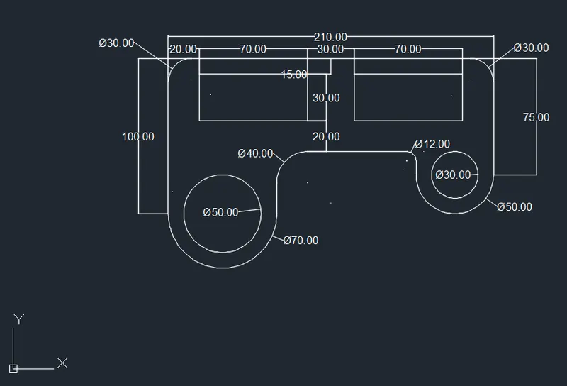
Q7:Aim: To draw the geometry using the direct distance entry method, and illustrate the procedure involved.
Procedure:
- Create a new drawing from the dropdown menu
- Select the imperial system and decimal units
- Change the insertion scale to meters
- Type L to activate line tool
- Activate orthomode (F8)
- Enter the first coordinate (100,100)
- Position the cursor and enter the distance 100
- Position the cursor and enter the distance 210
- Position the cursor and enter the distance 75
- Position the cursor and enter the distance 50
- Position the cursor and enter the distance 15
- Position the cursor and enter the distance 90
- Position the cursor and enter the distance 40
- Select the close option from the command bar
- Type C to activate circle tool
- Enter the coordinates of the centre of the circle(135,100)
- Select the diameter option in the command bar
- Enter the diameter of the circle 70
- Type C to activate circle tool
- Enter the coordinates of the centre of the circle(135,100)
- Select the diameter option in the command bar
- Enter the diameter of the circle 50
- Type C to activate circle tool
- Enter the coordinates of the centre of the circle(285,125)
- Select the diameter option in the command bar
- Enter the diameter of the circle 50
- Type C to activate circle tool
- Enter the coordinates of the centre of the circle(285,125)
- Select the diameter option in the command bar
- Enter the diameter of the circle 30
- Type TR to activate the trim tool
- Select the circle with a diameter 70 and press enter
- Select the cutting edge option and select the line in this circle and press enter
- Select the top portion of this circle to be trimmed off
- Type TR to activate the trim tool
- Select the circle with a diameter 50 and press enter
- Select the cutting edge option and select the line in this circle and press enter
- Select the top portion of this circle to be trimmed off
- Erase the extra lines
- Type REC to activate rectangle tool
- Enter the first corner as (120,190)
- Select the dimension option
- Enter the length 70 and width 30
- Select the other corner point
- Type CO to activate copy tool
- Select above rectangle and press enter
- Specify the basepoint as the bottom left corner of the rectangle
- Position the cursor and enter the distance 100
- Type F to activate fillet tool
- Select the radius option
- Enter the radius 15
- Select the first and second lines for fillet
- Type F to activate fillet tool
- Select the radius option
- Enter the radius 15
- Select the first and second lines for fillet
- Type F to activate fillet tool
- Select the radius option
- Enter the radius 6
- Select the first and second lines for fillet
- Type F to activate fillet tool
- Select the radius option
- Enter the radius 20
- Select the first and second lines for fillet
- Save the drawing
Q8: Aim: To draw the geometry using the direct distance entry method, and illustrate the procedure involved.
Procedure:
- Create a new drawing from the dropdown menu
- Select the imperial system and decimal units
- Change the insertion scale to meters
- Type C to activate circle tool
- Enter the coordinates of the centre of the circle(0.9,2.5)
- Select the diameter option in the command bar
- Enter the diameter of the circle 1.8
- Type C to activate circle tool
- Enter the coordinates of the centre of the circle(0.9,2.5)
- Select the diameter option in the command bar
- Enter the diameter of the circle 0.9
- Type CO to activate copy tool
- Select above two circles and press enter
- Specify the basepoint as the centre of the circle
- Position the cursor and enter the distance 8.55
- Type C to activate circle tool
- Enter the coordinates of the centre of the circle(5.175,2.5)
- Select the diameter option in the command bar
- Enter the diameter of the circle 5
- type C to activate circle tool
- Enter the coordinates of the centre of the circle(5.175,2.5)
- Select the diameter option in the command bar
- Enter the diameter of the circle 4
- Type L to activate line tool
- Select the nearest point of the circle of diameter 1.8 on the top as the starting point
- Select the tangent point of the circle of diameter 5 on the top as the endpoint
- Select the nearest point of the circle of diameter 1.8 on the bottom as the starting point
- Select the tangent point of the circle of diameter 5 on the bottom as the endpoint
- Type MI to activate mirror tool
- Select the above two line sand press enter
- Select the top and bottom quadrant points of the circle of diameter 5 as first and second points of mirror line and press enter
- Type TR to activate the trim tool
- Select the left circle of diameter 1.8 and press enter
- Select the cutting edge option and select the line in this circle and press enter
- Select the right portion of this circle to be trimmed off
- Type TR to activate the trim tool
- Select the right circle of diameter 1.8 and press enter
- Select the cutting edge option and select the line in this circle and press enter
- Select the left portion of this circle to be trimmed off
- Save the drawing
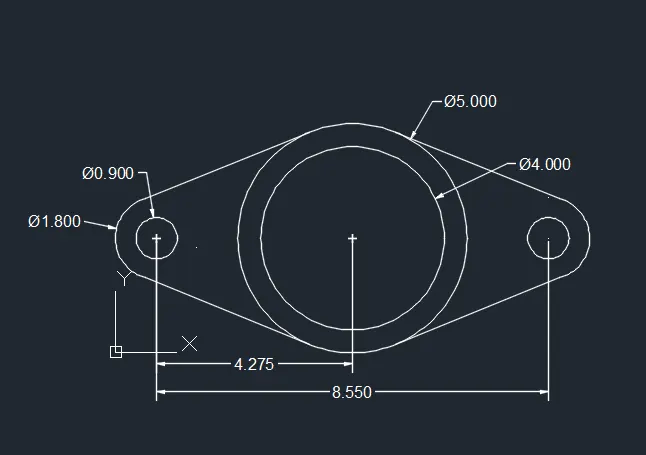
Q9: Aim: To draw the geometry using the direct distance entry method, and illustrate the procedure involved.
Procedure:
- Create a new drawing from the dropdown menu
- Select the imperial system and engineering units
- Change the insertion scale to inches
- type C to activate circle tool
- Enter the coordinates of the centre of the circle(8',8')
- Enter the radius of the circle 8'
- Type CO to activate copy tool
- Select the circle and press enter
- Specify the basepoint as the centre of the circle
- Position the cursor and enter the distance 32'6"
- Click the Arc tool in the ribbon
- Select the start, end, radius option
- Select the top nearest points in the two circles as the start point and endpoint
- Enter the radius of the arc 41'8"
- Click the Arc tool in the ribbon
- Select the start, end, radius option
- Select the bottom nearest points in the two circles as the start point and endpoint
- Enter the radius of the arc 20'10"
- Type TR to activate the trim tool
- Select two circles
- Select the cutting edge option and select the two arcs as cutting edges and press enter
- Select the inner portions of these circles to be trimmed off
- Save the drawing
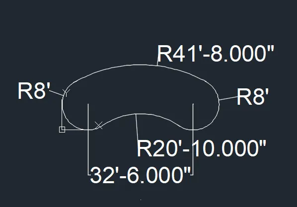
Q10: Aim: To draw the geometry using the direct distance entry method, and illustrate the procedure involved.
Procedure:
- Create a new drawing from the dropdown menu
- Select the imperial system and engineering units
- Change the insertion scale to inches
- Type REC to activate rectangle tool
- Enter the first corner as (1,1)
- Select the dimension option
- Enter the length 5 and width 5
- Select the other corner point
- Type REC to activate rectangle tool
- Enter the first corner as (1.2,1.2)
- Select the dimension option
- Enter the length 4.6 and width 4.6
- Select the other corner point
- Type RO to activate rotation tool
- Select the above 2 rectangles
- Specify the base point as the left bottom corner of the bigger rectangle
- Select the copy option
- Specify the rotation angle as 45 degrees
- Type M to activate the move tool
- Select the Second set of rotated rectangles
- Select one of the corners as the base point
- Move those two rectangles so that the corners of the second set of rectangles align with the centre point of the sides of the first set of rectangles
- Type TR to activate the trim tool
- Press enter again to select the select all option
- Do the trimming for all the sides
- Save the drawing
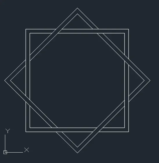
Q11: Aim: To draw the geometry using the direct distance entry method, and illustrate the procedure involved.
Procedure:
- Create a new drawing from the dropdown menu
- Select the imperial system and engineering units
- Change the insertion scale to inches
- Type L to activate line tool
- Activate orthomode (F8)
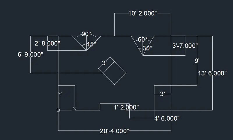
- Enter the first coordinate (10'2",13'6")
- Position the cursor and enter the distance 10'2"
- Position the cursor and enter the distance 9'
- Position the cursor and enter the distance 3'
- Position the cursor and enter the distance 4'6"
- Position the cursor and enter the distance 4'6"
- Position the cursor and enter the distance 1'2'
- Position the cursor and enter the distance 2'8"
- Select the close option from the command bar
- Type MI to activate mirror tool
- Select all the lines and press enter
- Select the top and bottom points of the central line as the first and second points of the mirror line and press enter
- Type REC to activate rectangle tool
- select any point on the central line as the first corner
- Select the dimension option
- Enter the length 3' and width 3'
- Select the other corner point
- Type RO to activate rotation tool
- Select the rectangle
- Specify the base point as the left bottom corner of the bigger rectangle
- Specify the rotation angle as 45 degrees
- Type M to activate the move tool
- Select the rectangle and press enter
- Select any corner of the rectangle as the base point
- Align the rectangle to the centre of the line
- Type L to activate line tool
- Select the centre of the top left 10'2" line as the first point
- Position the cursor and enter the distance 2'8"
- Type L to activate line tool
- Enter the first coordinate (2'5",13'6")
- Select the bottom point o the 2'8" line as the second point
- Type MI to activate mirror tool
- Select the above line and press enter
- select the endpoints of the vertical 2'8" lines as the first and second points of the mirror line and press enter
- Type L to activate line tool
- Select the centre of the top right 10'2" line as the first point
- Position the cursor and enter the distance 3'7"
- Click the arc tool on the ribbon
- Select the centre start angle option
- Select the centre as the bottom of the above line and start point as the top of the above line and angle 60 degrees
- Type L to activate line tool
- Join the centre of the arc and bottom of the 3'7" line
- Type RO to activate rotation tool
- Select the arc and above line
- Select the bottom of the above line as the base point
- Rotate it to align with the vertical line
- Type L to activate line tool
- Join the bottom of the vertical line and left edge of the arc and extend it to meet the 10'2" line
- Repeat the same on the right side
- Type TR to activate the trim tool
- Press enter again to select the select all option
- Trim the extra lines in the top 20'4" line
- Delete the extra centre line
- Save the drawing