Creating a Floor plan, Footing detail and Isometric view using AutoCad
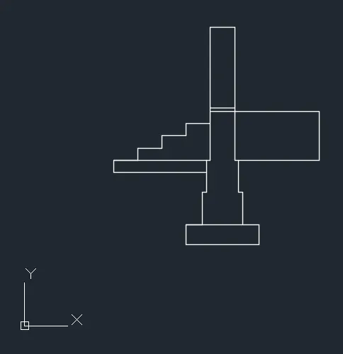
Q1: Aim: To draw the C.S of the load-bearing wall over spread footing using the direct distance entry method, and illustrate the procedure involved.
Procedure:
- Create a new drawing from the dropdown menu
- Select the imperial system and decimal units
- Change the insertion scale to meters
- Type REC to activate the rectangle tool
- Type the first point coordinate as (2,1)
- Select the dimension option
- Type the length as 0.9
- Type the width as 0.25
- Select the second corner of the rectangle
- Type L to activate the line tool
- Click the left top of the rectangle
- Position the cursor and enter the distance of 0.2
- Position the cursor and enter the distance of 0.4
- Position the cursor and enter the distance of 0.05
- Position the cursor and enter the distance of 0.4
- Position the cursor and enter the distance of 0.05
- Position the cursor and enter the distance of 1.65
- Position the cursor and enter the distance of 0.3
- Position the cursor and enter the distance of 1.65
- Position the cursor and enter the distance of 0.05
- Position the cursor and enter the distance of 0.4
- Position the cursor and enter the distance of 0.05
- Position the cursor and enter the distance of 0.4 and press enter
- Type O to activate the offset tool
- Specify the offset distance as 1
- Select the line with 0.3m length on the top
- Specify a point on the side of the offset
- Type L to activate the line tool
- Select the right-hand side corner of the footing
- Position the cursor and enter the distance of 1
- Position the cursor and enter the distance of 0.6
- Position the cursor and enter the distance of 1.35 and press enter
- Type L to activate the line tool
- Select the left-hand side corner of the footing
- Position the cursor and enter the distance of 1.15
- Position the cursor and enter the distance of 0.15
- Position the cursor and enter the distance of 1.15
- Type L to activate the line tool
- Select the left top corner of the above line
- Position the cursor and enter the distance of 0.3
- Position the cursor and enter the distance of 0.15
- Position the cursor and enter the distance of 0.3 and press enter
- Type CO to activate the copy tool
- Select the 0.15 line and 0.3 line and press enter
- Specify the base point
- Copy it 2 times and press enter
- Save the drawing
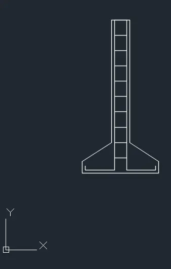
Q2: Aim: To draw the C.S of the isolated footing using the direct distance entry method, and illustrate the procedure involved.
Procedure:
- Create a new drawing from the dropdown menu
- Select the imperial system and decimal units
- Change the insertion scale to meters
- Type L to activate the line tool
- Enter the first coordinate (1,1)
- Position the cursor and enter the distance of 0.4
- Position the cursor and enter the distance of 0.38
- Position the cursor and enter the distance of 1.6
- Position the cursor and enter the distance of 0.24
- Position the cursor and enter the distance of 1.6
- Position the cursor and enter the distance of 0.38
- Position the cursor and enter the distance of 0.4
- Select the close option from the command bar
- Type CHA to activate the chamfer tool
- Select the distance option
- Enter the first distance 0.25
- Enter the second distance 0.38
- Select the multiple option
- Select the first line of the foundation on the left side and then second line to chamfer
- Select the first line of the foundation on the right side and then second line to chamfer
- Type L to activate the line tool
- Enter the first coordinate (1.04,1.09)
- Position the cursor and enter the distance of 0.05
- Position the cursor and enter the distance of 0.38
- Position the cursor and enter the distance of 1.96
- Position the cursor and enter the distance of 0.4
- Position the cursor and enter the distance of 0.16
- Position the cursor and enter the distance of 1.96
- Position the cursor and enter the distance of 0.38
- Position the cursor and enter the distance of 0.05
- Type O to activate the offset tool
- Specify the offset distance as 0.2
- Select the line with 0.16m length on the top
- Specify a point on the side of the offset 9 times to draw the offset line 9 times
- Save the drawing
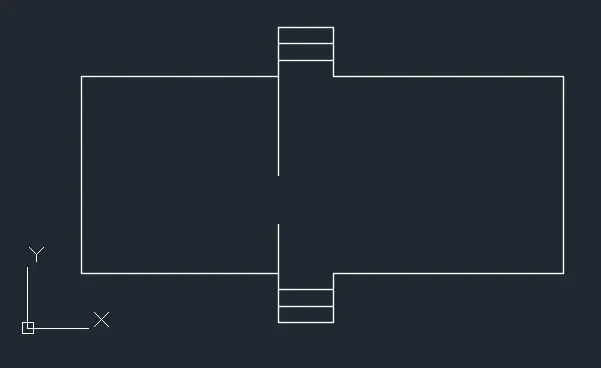
Q3: Aim: To draw the line diagram of a two bedroom building using the direct distance entry method, and illustrate the procedure involved.
Procedure:
- Create a new drawing from the dropdown menu
- Select the imperial system and decimal units
- Change the insertion scale to meters
- Type L to activate the line tool
- Enter the first coordinate (1,1)
- Position the cursor and enter the distance of 3.6
- Position the cursor and enter the distance of 3.6
- Position the cursor and enter the distance of 0.9
- Position the cursor and enter the distance of 1
- Position the cursor and enter the distance of 0.9
- Position the cursor and enter the distance of 4.2
- Position the cursor and enter the distance of 3.6
- Position the cursor and enter the distance of 4.2
- Position the cursor and enter the distance of 0.9
- Position the cursor and enter the distance of 1
- Position the cursor and enter the distance of 0.9
- Select the close option from the command bar
- Type O to activate the offset tool
- Specify the offset distance as 0.3
- Select the line with 1m length on the top
- Specify a point on the side of the offset 2 times to draw the offset line 2 times
- Type O to activate the offset tool
- Specify the offset distance as 0.3
- Select the line with 1m length on the bottom
- Specify a point on the side of the offset 2 times to draw the offset line 2 times
- Type L to activate the line tool
- Select the corner point at the bottom
- Position the cursor and enter the distance of 0.9
- Select the corner point at the top
- Position the cursor and enter the distance of 1.8
- Save the drawing
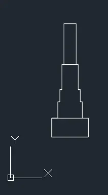
Q4: Aim: To draw the CS of load bearing wall showing foundation details using the direct distance entry method, and illustrate the procedure involved.
Procedure:
- Type REC to activate the rectangle tool
- Type the first point coordinate as (1,1)
- Select the dimension option
- Type the length as 0.9
- Type the width as 0.45
- Select the top left corner of the rectangle
- Type L to activate the line tool
- Select the top left corner of the rectangle
- Position the cursor and enter the distance of 0.15
- Position the cursor and enter the distance of 0.4
- Position the cursor and enter the distance of 0.05
- Position the cursor and enter the distance of 0.3
- Position the cursor and enter the distance of 0.05
- Position the cursor and enter the distance of 0.6
- Position the cursor and enter the distance of 0.4
- Position the cursor and enter the distance of 6
- Position the cursor and enter the distance of 0.05
- Position the cursor and enter the distance of 0.3
- Position the cursor and enter the distance of 0.05
- Position the cursor and enter the distance of 0.4
- Type L to activate the line tool
- Select the top left corner
- Position the cursor and enter the distance of 0.05
- Position the cursor and enter the distance of 1
- Position the cursor and enter the distance of 0.3
- Position the cursor and enter the distance of 1
- Save the drawing
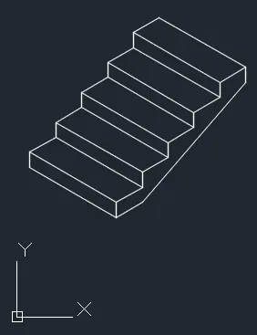
Q5: Aim: To draw the isometric view of steps using the direct distance entry method, and illustrate the procedure involved.
Procedure:
- Select isometric snap from draft settings
- Type L to activate the line tool
- Type the first point coordinate as (1,1)
- Select isometric right
- Position the cursor and enter the distance of 0.15
- Position the cursor and enter the distance of 0.3
- Type CO to activate the copy tool
- Select the 0.15 line and 0.3 line and press enter
- Specify the base point press enter
- Copy it 4 times and press enter
- Select isometric left
- Type L to activate the line tool
- Select the bottom end of the line
- Position the cursor and enter the distance of 1
- Position the cursor and enter the distance of 0.15
- Position the cursor and enter the distance of 1
- Type L to activate the line tool
- Select the left top corner of the rectangle
- Position the cursor and enter the distance of 0.3
- Type CO to activate the copy tool
- Select the isometric left lines for the first step press enter
- Specify the base point press enter
- Copy it 4 times and press enter
- Type L to activate the line tool
- Select the top left corner of the step
- Position the cursor and enter the distance of 1
- Position the cursor and enter the distance of 0.15
- Type L to activate the line tool
- Select the bottom right corner of the step
- Position the cursor and enter the distance of 0.3
- Deactivate isometric snap from draft settings
- Type L to activate the line tool
- Connect the two lines at the bottom of the steps
- Save the drawing
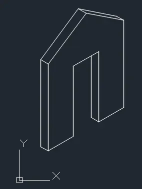
Q6: Aim: To draw the isometric view gable wall using the direct distance entry method, and illustrate the procedure involved.
Procedure:
- Select isometric snap from draft settings
- Select isometric left (F5)
- Type L to activate the line tool
- Type the first point coordinate as (1,1)
- Position the cursor and enter the distance of 0.3
- Position the cursor and enter the distance of 3
- Position the cursor and enter the distance of 0.3
- Position the cursor and enter the distance of 0.15
- Select the close option from the command bar
- Select isometric right (F5)
- Type L to activate the line tool
- Select the bottom right corner of the rectangle
- Position the cursor and enter the distance of 1
- Position the cursor and enter the distance of 2.42
- Position the cursor and enter the distance of 1
- Position the cursor and enter the distance of 2.42
- Position the cursor and enter the distance of 1
- Position the cursor and enter the distance of 3
- Position the cursor and enter the distance of 3
- Type L to activate the line tool
- Select the top right corner of the rectangle
- Position the cursor and enter the distance of 1.5
- Position the cursor and enter the distance of 1 and press enter
- Select isometric left (F5)
- Type CO to activate the copy tool
- Select the top isometric left line of the rectangle press enter
- Specify the base point press enter
- Copy it 3 times and press enter
- Type L to activate the line tool
- Select the right bottom corner of the door
- Position the cursor and enter the distance of 0.3
- Position the cursor and enter the distance of 3
- Select the above vertical line of 3m length
- Click at the top of this vertical line
- Select one point on the top line of the door to reduce its length to match the door
- Deactivate isometric snap from draft settings
- Type L to activate the line tool
- Connect the copied isometric left lines at the top press enter
- Delete the extra lines
- Save the drawing