Creating a Residence Layout, Seating plan, Toilet and Utility room plan using AutoCad
Q1
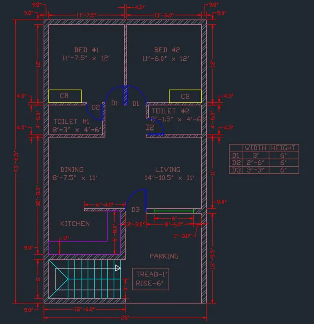
AIM : To draw the given figure using AutoCAD
PROCEDURE
STEP 1 :
Type drafting setting or OS in the command box and press enter
open snap and grid setting
Change snap spacing to 1
Change grid spacing to 1
Change major line every grid line to 5
Turn off adaptive grid and turn on display grid beyond limits
STEP 2 :
Type unit or UN in the command box and press enter
Set type of unit as engineering and precision as 0’-0.0”
In Insertion scale set unit as inches
STEP 3 :
Type dimension style manager or D in the command box and press enter
Modify primary units as engineering and precision as 0’-0.0”
STEP 4 :
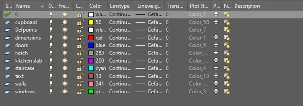
Type layer or LA in the command box and press enter
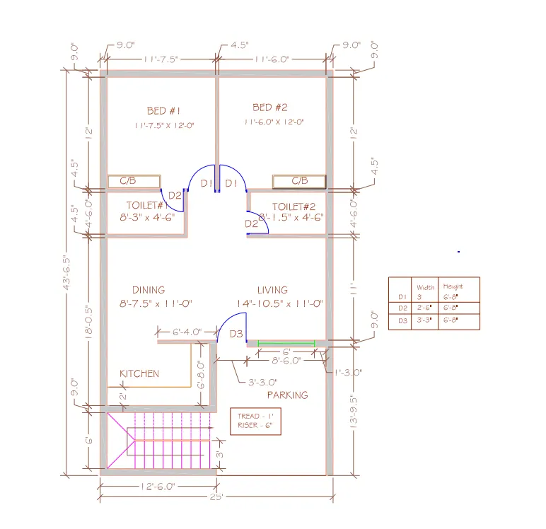
Create new layers according to drawing given
STEP 5 :
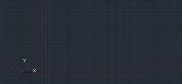
Type construction line or XL in the command box and press enter
Specify a point or [Hor/Ver/Ang/Bisect/Offset]: Horizontal line and press enter
Select any point and press enter
Specify a point or [Hor/Ver/Ang/Bisect/Offset]: Vertical line
Select any point and press enter
STEP 6 :
Type offset or O in the command box and press enter
Specify offset distance : 25’
Select object to offset : Exit the command
Type offset or O in the command box and press enter
Specify offset distance : 43’6.5”
Select object to offset : Exit the command
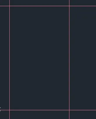
STEP 7 :
Type trim or TR in the command box and press enter
Select the object which needs to be trimmed

STEP 8 :
Type offset or O in the command box and press enter
Specify offset distance : 9”
Select object to offset : Exit the command
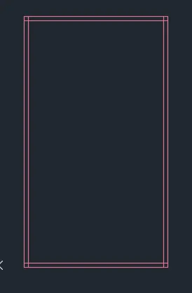
STEP 9 :
Type offset or O in the command box and press enter
Offset the horizontal lines which is given
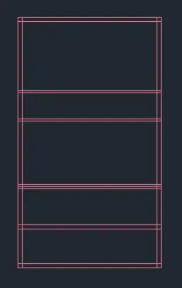
STEP 10 :
Type offset or O in the command box and press enter
Offset the vertical lines which is given
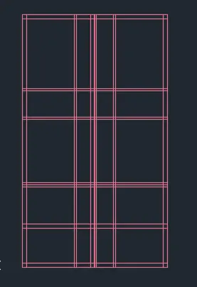
STEP 11 :
Type trim or TR in the command box and press enter
Select the object which needs to be trimmed
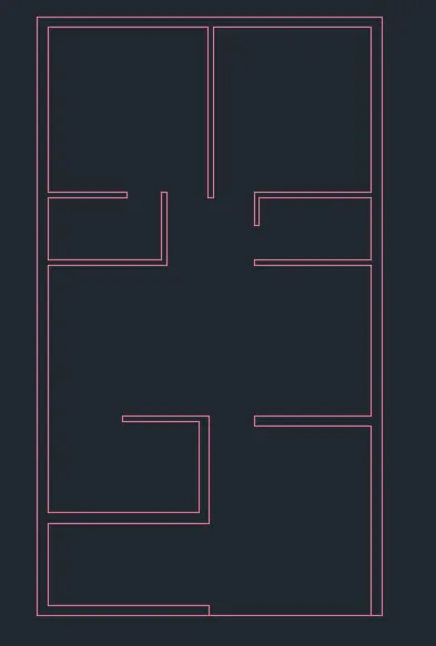
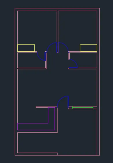
STEP 12 :
Draw windows, doors, kitchen slab and cupboard using line command, rectangle command and arc command
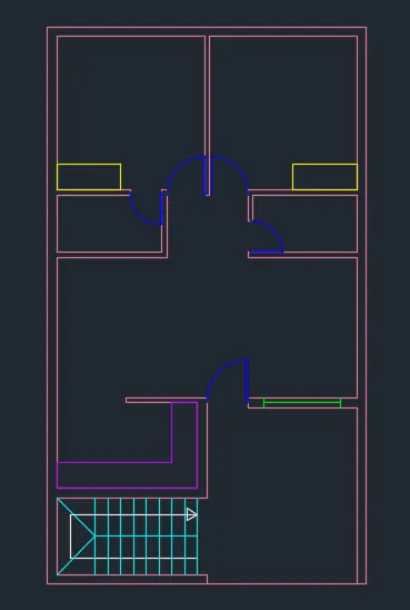
STEP 13 :
Draw stairs using line command and offset command
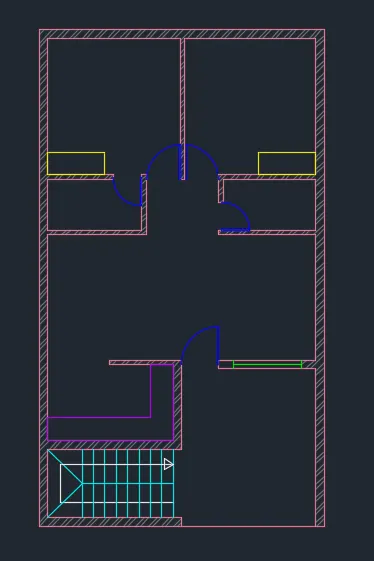
STEP 14 :
Type hatch or HA in the command box and press enter
Hatch the wall internal part
STEP 15 :
Type DIM in the command box and press enter
Add required dimensions to drawing
Type TEXT in the command box and press enter
Add room names
RESULT
The figure given is drawn using construction line tool, offset tool, trim tool, hatch tool, arc tool, dimension tool and text tool.
Q2
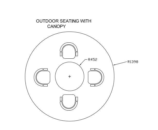
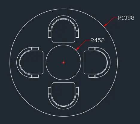
AIM : To draw the given figure using AutoCAD
PROCEDURE
STEP 1 :
Type drafting setting or OS in the command box and press enter
open snap and grid setting
Change snap spacing to 1
Change grid spacing to 1
Change major line every grid line to 5
Turn off adaptive grid and turn on display grid beyond limits
STEP 2 :
Type unit or UN in the command box and press enter
Set type of unit as decimal and precision as 0
In Insertion scale set unit as Millimetres
STEP 3 :
Type dimension style manager or D in the command box and press enter
Modify primary units as decimal and precision as 0
STEP 4 :
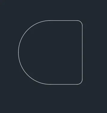
Type Rectangle or REC in the command box and press enter
Draw a rectangle of size 600,600

STEP 5 :
Type fillet or F in the command box and press enter
Current settings: Mode = TRIM, Radius = 0
Select first object : r (radius of the fillet)
Specify fillet radius : 300
Select first object : click on the first line
Select second object : click on the second line
Type fillet or F in the command box and press enter
Current settings: Mode = TRIM, Radius = 0
Select first object : r (radius of the fillet)
Specify fillet radius : 300
Select first object : click on the first line
Select second object : click on the second line
Type fillet or F in the command box and press enter
Current settings: Mode = TRIM, Radius = 0
Select first object : r (radius of the fillet)
Specify fillet radius :50
Select first object : click on the first line
Select second object : click on the second line
Type fillet or F in the command box and press enter
Current settings: Mode = TRIM, Radius = 0
Select first object : r (radius of the fillet)
Specify fillet radius :50
Select first object : click on the first line
Select second object : click on the second line
STEP 6 :
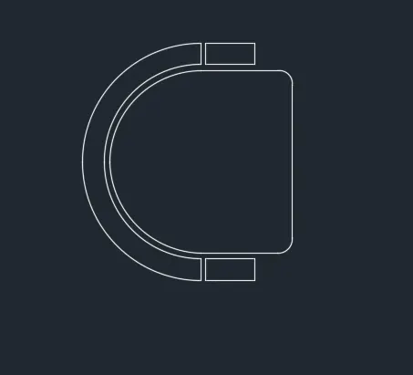
Type offset or O in the command box and press enter
Specify offset distance : 20
Select object to offset : Exit the command
Type offset or O in the command box and press enter
Specify offset distance : 70
Select object to offset : Exit the command
Type line or L in the command box and press enter
Draw the line where ever required
Type Trim or TR in the command box and press enter
Select the object which needs to be trimmed
STEP 7 :
Type circle or C in the command box and press enter
Specify center point for circle : select the point
Specify radius of circle : 452 and press enter
Type circle or C in the command box and press enter
Specify center point for circle : select the point
Specify radius of circle : 1398 and press enter

STEP 8 :
Type Copy or CO in the command box and press enter
Copy the drawn chair figure and place inside the outer circle

STEP 9 :
Type Array in the command box and press enter
Select polar array and specify number as 4
STEP 10 :
Type DIM in the command box and press enter
Add required dimensions to drawing
RESULT
The figure given is drawn using rectangle tool, fillet tool, line tool, trim tool, circle tool, array tool and dimension tool
Q3
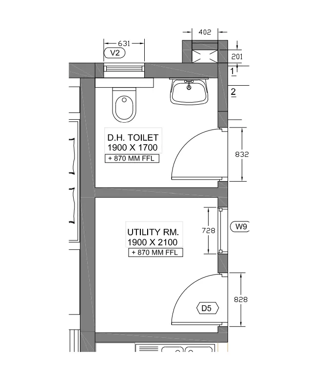
AIM : To draw the given figure using AutoCAD
PROCEDURE
STEP 1 :
Type drafting setting or OS in the command box and press enter
open snap and grid setting
Change snap spacing to 1
Change grid spacing to 1
Change major line every grid line to 5
Turn off adaptive grid and turn on display grid beyond limits
STEP 2 :
Type unit or UN in the command box and press enter
Set type of unit as decimal and precision as 0
In Insertion scale set unit as Millimetres
STEP 3 :
Type dimension style manager or D in the command box and press enter
Modify primary units as decimal and precision as 0
STEP 4 :
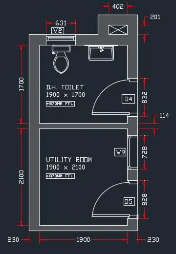
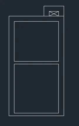
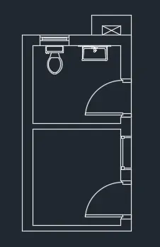
Using line and offset command draw the given layout plan
Consider the main wall thickness as 230mm and internal wall as 114mm
STEP 5 :
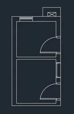
Using line, arc, offset and trim command draw the doors, window and ventilator as per the given figure
STEP 6 :
Draw toilet top view and sink top view using the required command.
STEP 7 :
Type DIM in the command box and press enter
Add required dimensions to drawing
Type TEXT in the command box and press enter
Add room names
Type hatch or HA in the command box and press enter
Hatch the wall internal part
RESULT
The figure given is drawn using line tool, offset tool, trim tool, hatch tool, arc tool, dimension tool and text tool.