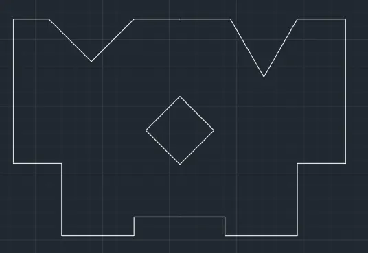
Drafting of various geometries using Chamfer, Fillet tool in AutoCad
1.DECIMAL:
AIM: To draw picture using autocad
PROCEDURE:
- To draw layout:
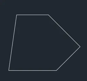
- Command : LINE
- LINE specify first point : 1,1
- LINE specify next point or undo : @3,0
- LINE specify next point or undo : @2.12<45
- LINE specify next point or undo : @2.83<135
- LINE specify next point or undo : @-2,0
- And click close
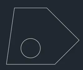
- To draw circles inside the layout:
- Command : circle
- enter center of the circle : 2.5,2
- enter circle diameter : 1.2
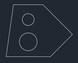
- command : circle
- enter center of the circle : 2.5,3.5
- enter circle diameter : 0.8
- The ouput is shown in the result
RESULT: The resultant is
2:
AIM: To draw the picture using autocad
PROCEDURE:
- command : line
- enter the first point : click on any point on the screen
- enter the next point : @8',0
- enter the next point : @0,-1'9"
- enter the next point : @2'10"<225(270-45)
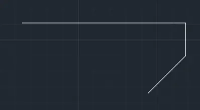
- press esc
- command : line
- enter the first point : click on the starting point of the 8' line
- enter the second point : @0,-3'5"
- enter the next point : @3'<315(360-45)
- enter the next point : @2'6"<45
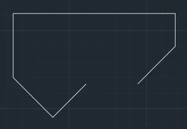
- enter the next point : click on the other end of the line to close the figure
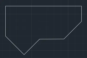
RESULT:
3.ENGINEERING:
AIM: To draw picture using autocad
PROCEDURE:
- To draw layout:
- command : units
- now select the architectural units
- in the drop down select 1/16
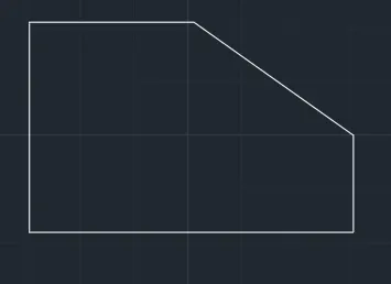
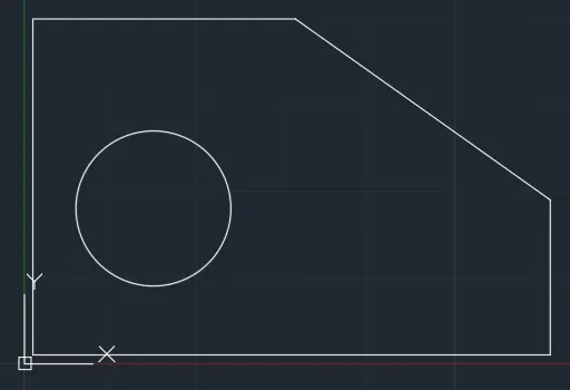
- command : polyline
- enter the first point : 1,1
- enter the next point : @-2'6.5",0
- enter the next point : @0,-3'3"
- enter the next point : @5'0.1",0
- enter the next point : @0,1'6"
- and then click close
- To draw cicrcle inside the layout:
- command : circle
- specify the center of the circle as (1'3",1'6")
- enter the diameter of the circle : 1'6"
- The final output is shown in the result
RESULT:
4.
AIM: To draw the picture using autocad
PROCEDURE:
- change the units - command : units
- starting from the bottom of the layout
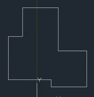
- command : pline
- enter the first point : 1,1
- enter the next point : @2.50,0 (calculate the length 5.50-3.00=2.50)
- enter the next point : @0,2.50
- enter the next point : @-2.00,0
- enter the next point : @0,3.00(calculate the length 5.50-2.50=2.00)
- enter the next point : @-2.50,0
- enter the next point : @0,-2.00(calculate the length 5.50-3.50=2.00)
- enter the next point : @-1.00,0(calculate the length 5.50-2.50-2.00=1.00)
- enter the next point : @0,3.00(calculate the length 3.50=0.5=3.00)
- enter the next point : @3.00,0
- And then click close
RESULT:
5:
AIM: To draw the picture using autocad
PROCEDURE:
- To draw the layout:
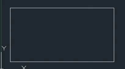
- command : line
- specify first point : 1,1
- specify next point : @11.50,0
- specify next point : @0,6
- specify next point :@-11.50,0
- And then click close
- we get the picture like this
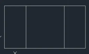
- command : offset
- select the option : through
- select the object : click the left side line of thr rectangle
- enter the value : 3 (calculate the length 4.25-2.75=1.5, 1.5+1.5=3)
- now in the similar way again enter the command : offset
- select the option : through
- select the object : click the right side line of the rectangle
- we get this output
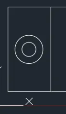
- To draw the holes:
- put on the object snap on and click on the center option
- command : circle
- enter center : 2.50,4
- select the diameter option and enter the diameter as 1
- command : circle
- enter center the center of the circle : move the cursor inside the circle ,as it shows the center of the previous circle and click on the center
- select the diameter option and enter the diameter as 2
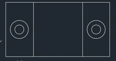
- on the other side also we are going to draw the holes
- command : circle
- enter center of the circle : 11,4
- select the diameter option and enter the diameter as 1
- command : circle
- enter center the center of the circle : move the cursor inside the circle ,as it shows the center of the previous circle and click on the center
- select the diameter option and enter the diameter as 2
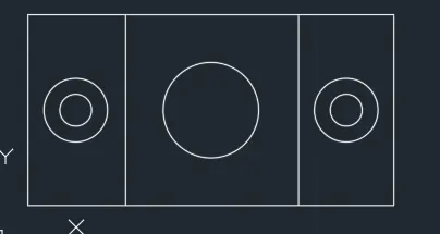
- To draw the hole in the center of the layout command : circle
- enter the center of the circle : 6.75,4
- Select the diameter option and enter the diameter : 3
- the final output is shown the result
RESULT:
6:
AIM: To draw the picture using autocad
PROCEDURE:
- To draw front view of the picture:
- command: line
- enter first point : 1,1
- enter next point : @1.5,0
- enter next point : @0,1.5
- enter next point : @-0.5,0
- enter next point : @-0.5,0
- enter next point : @-0.5,0
- enter the next point : @0,-1.5
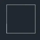
- enter the next point : @0,0.5
- enter the next point : @0.5,0
- enter the next point : @0.5,0
- enter the next point : @0.5,0
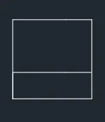
- command : line
- enter the first point : click the first point on the line
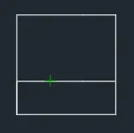
- enter the next point : click on the first point on the above line
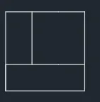
- again command : line
- enter the first point : click on the adjacent point on the line
- enter next point : click on the adjacent point on the above line
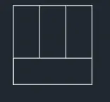
- To draw the left side view of the picture:
- command : line
- enter the first point : 3.5,1
- enter the next point : @2,0
- enter the next point : @-0.5,0
- enter the next point : @0,-1
- enter the next point : @-1.5,0
- And then click close
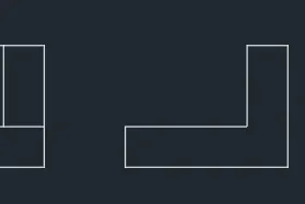
- command : line
- enter the first point : keep the cursor on the edge of the picture ,as object snap is on it shows the point
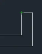
- click on the point
- enter the next point : keep the cursor on the other point and click on it

- To draw the top view of the picture :
- command : line
- enter the first point : 3.5,3.5
- enter the next point : @2,0
- enter the next point : @0,1.5
- enter the next point : @-0.5,0
- enter the next point : @-1.5,0
- enter the next point : @-0.5,0
- enter the next point : @-0.5,0
- enter the next point : @-0.5,0
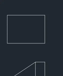
- command : line
- enter the first point : click top edge of the rectangle as the object snap shows the point and click on the point
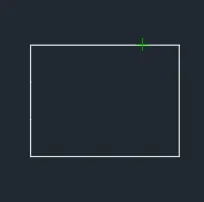
- enter the next point : @0,-0.5
- enter the next point : @0,-0.5
- enter the next point : @0,-0.5
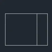
- command : line
- enter first point : keep the cursor on the inside line of the rectangle ,object snap shows the point on the line
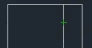
- click on the point
- enter the next point : @-1.5,0
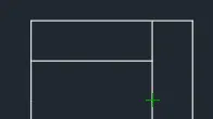
- command : line
- enter first point : keep the cursor on the inside line of the rectangle ,object snap shows the point on the line
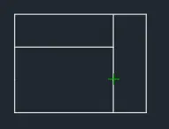
- click on the point
- enter the next point : @-1.5,0
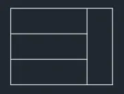
RESULT:
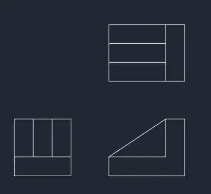
7:
AIM: To draw the picture using autocad
PROCEDURE:
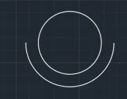
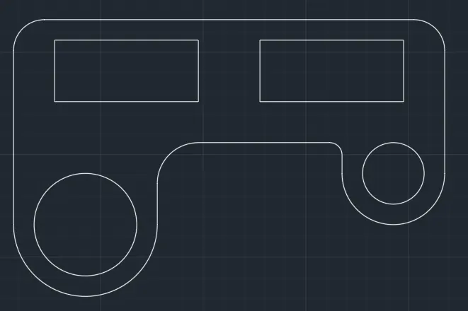
- command : line
- enter the first point : click on any point on the screen
- enter the second point : @70,0 (since,the radius of the arc is 35)
- command : arc
- select the option: start,end,radius
- click on the starting point of the line to specify the starting point of the arc
- click on the end point o the line to specify the end point of the arc
- enter the radius of the arc as 35
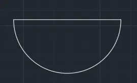
- command : circle
- enter the center of the circe : click on the mid point of the line
- enter the diameter of the circle : 50
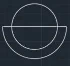
- command : erase
- select the objects: select the horizontal line drawn
- command : line
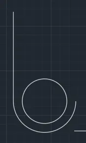
- enter the first point : click on the start point of the previously drawn arc
- enter second point : @0,100
- command : line
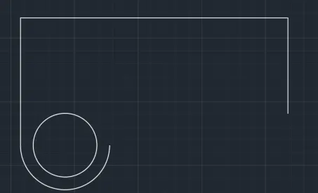
- enter first point : click on the end point of the vertical line drawn
- enter next point : @210,0
- enter next point : @0,-75
- command : line
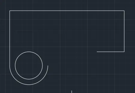
- enter first point : click on the end point of the vertical line drawn previously
- enter next point : @-50,0
- command : arc
- select the option : start ,end,radius
- select the start point of the horizontal line drawn previously as the start point of the arc
- to get the required direction of the arc ,hold ctrl button
- and enter the radius of the arc : 25
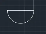
- command : circle
- enter the center of the circle : click on the mid point of the horizontal line
- enter the diameter of the circle : 30
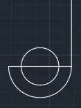
- command : erase
- select the horizontal line and press enter button
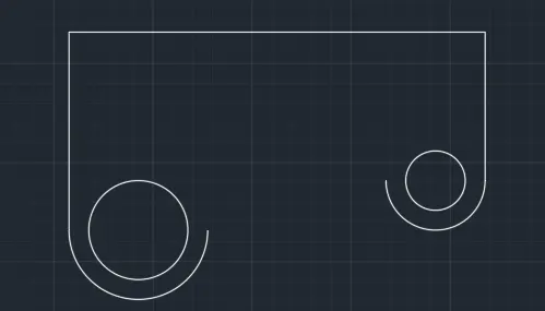
- command : line
- enter the first point : click on the end point of the 25 radius arc
- enter the second point : @0,15 (as the length of line is equal to radius of the circle and the circle radius is 15)
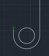
- enter the next point : @-90,0(210-70-30=90)
- enter the next point : click on the end point of the 35 radius arc
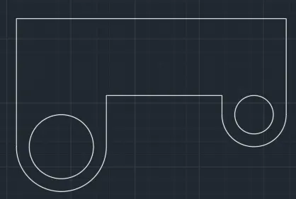
- command : line
- enter the first point : click on the intersection point of 100 units line and 210 units line
- enter the second point : @20,0
- enter the second point : @0,-10
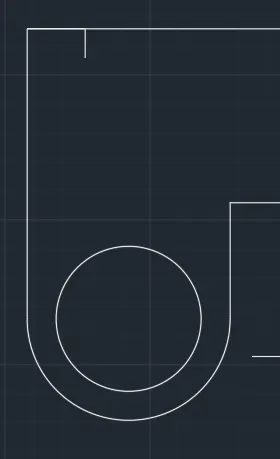
- command : rectangle
- enter the corner point of the rectangle: click on the end point of the previously drawn vertical point
- select the dimensions option
- enter the length : 70 and breadth :30
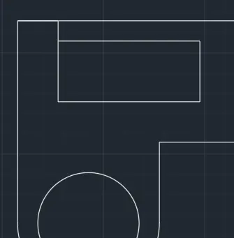
- command : erase
- select the vertical line above the rectangle
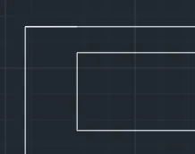
- command : copy
- select the object : select the rectangle
- select the base point : select the bottom right corner of the rectangle
- enter the distance : 100
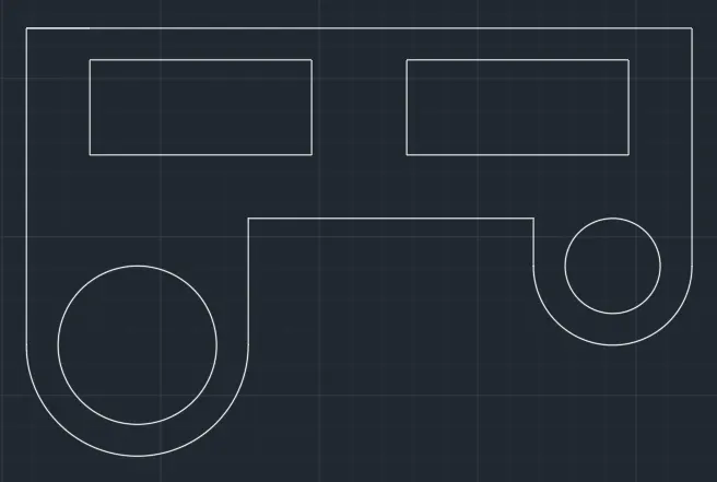
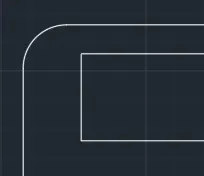
- command : fillet
- select radius option
- enter the radius of the fillet : 15
- select the the first object : click on the 100 units vertical unit
- select the second object : click on the 210 units horizontal line
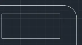
- command : fillet
- select radius option and enter the radius :15
- select the first object : select the 210 units line
- select the second point : select the 70 units vertical line
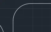
- command : fillet
- select radius option and enter the radius :6
- select the first object : select the 15 units vertical line
- select the second point : select the 90 units horizontal ine

- command : fillet
- select radius option and enter the radius :20
- select the first object : select the 90 units horizontal line
- select the second object : select the adjacent vertical line attached to the arc of radius 35
RESULT: The resultant output is
8:
AIM: To draw the picture using autocad
PROCEDURE:
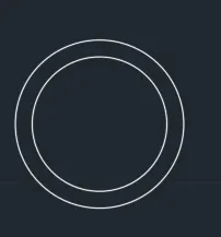
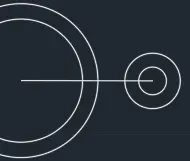
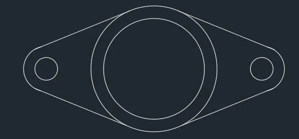
- command : circle
- enter the center point: click on any point on the screen
- enter the diameter of the circle: 5
- command : circle
- enter the center point : click on the center of the previous circle
- enter the diameter of the circle as 4
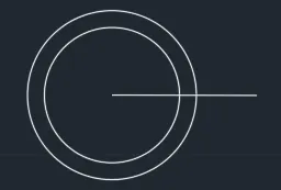
- command : line
- enter the first point : click on the center of the circle
- enter the next point : @4.275,0
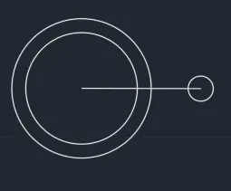
- command : circle
- enter the center of the circle : click on the right side edge of the line drawn previously
- enter the diameter of the circle as 0.9
- command : circle
- enter the center of the circle : click on the center of 0.9 dia circle
- enter the radius of the circle : 0.9
- command : line
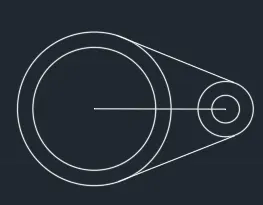
- enter the first point of the line : click on the top of the 0.9 radius circle
- enter the next point : click on the top of the 5 dia circle

- command : line
- enter the first point of the line : click on the bottom of the 0.9 radius circle
- enter the next point : click on the bottom of the 5 dia circle
- command : erase
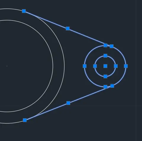
- select the erase object : select the horizontal line drawn
- and click enter
- select the objects as shown below
- command : mirror
- specify the first point of the mirror line : select the center of the 5dia circle
- specify the second point on the mirror line : keep the cursor in the required direction and click on any point
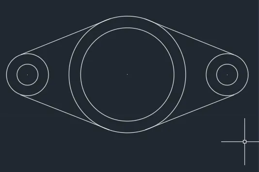
- command : trim
- select the 0.9 radius circle inside part only
- and do it another side of the circle
- final output is shown in the result
RESULT:
9:
AIM: To draw the picture using autocad
PROCEDURE:
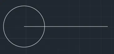
- command : line
- enter the first point : click on any point on the screen
- enter the second point : @32'6"
- command : circle
- enter the center of the circle : select the starting point of the horizontal line
- enter the diameter : 8'
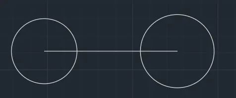
- command : circle
- enter the center of the circle : select the end point of the horizontal line
- enter the diameter : 9'
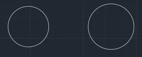
- command : erase
- select the object : select the horizontal line
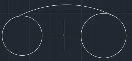
- command : arc
- select start , end , radius option
- select the start point : click on the top of the 9' radius circle
- select the end point : click on the top of the 8' radius circle
- enter the radius of the arc : 41'8"
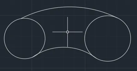
- command : arc
- select start , end , radius option
- select the start point : click on the bottom of the 9' radius circle
- select the end point : click on the bottom of the 8' radius circle
- enter the radius of the arc : 20'10'
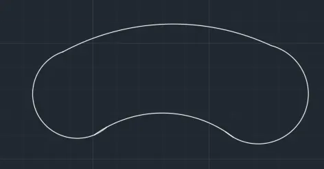
- command : trim
- select the inside part of the two circles
- the final output is shown in the result
RESULT:
10:
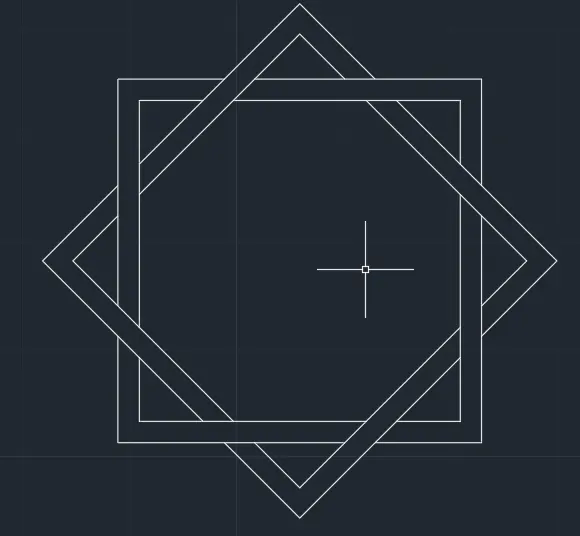
AIM: To draw the picture using autocad
PROCEDURE:
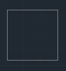
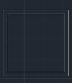
- command : rectang
- enter the first corner point : click on any point on the screen
- select dimensions option
- enter the length:30
- enter the breadth : 30
- command: offset
- enter the offset distance : 2
- select the object: select the rectangle drawn
- click on outside of the rectangle
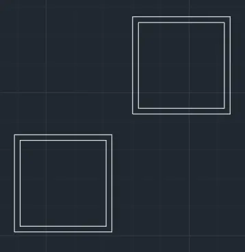
- command : copy
- select the object : select both the rectangles
- select the basepoint : click on any corner of the object
- move to any part of the screen and click on it
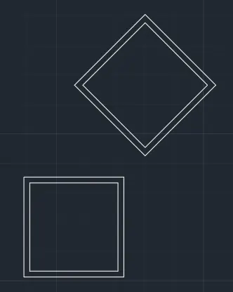
- command : rotate
- select the objects : select anyone of the pictures
- select basepoint : select any one corner of the selected picture
- specify rotation angle : 45
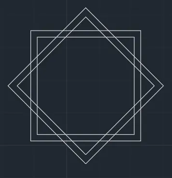
- command : move
- select objects : select the rotated object
- specify base point : click on the geometric center of the rotated object
- specify second point : click on the geometric center of the other object
- command : trim
- select the objects : select the required objects to be trimmed and press enter
RESULT:
11:
AIM: To draw the picture using autocad
PROCEDURE:
- command : units
- change the unit by selecting architectural from drop down
- and precision to 1/16 and insertion scale to inches
- command : line
- enter the first point : click on any point on the screen
- enter the second point : @0,-9"
- enter the next point : @3',0
- enter the next point : @0,-4'6"
- enter the next point : @4'6",0
- enter the next point : @0,1'2"
- enter the next point : @2'10",0
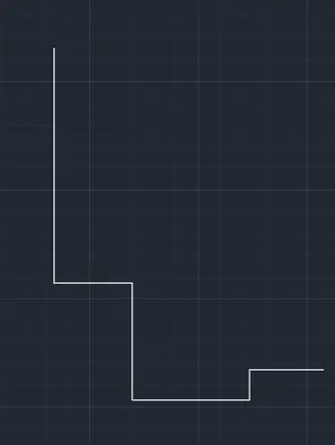
- command : mirror
- select the objects : select the entire picture drawn
- specify the first point of the mirror line : click on the end point of the 2'10" line
- specify the second point : keep the image in the required direction and click on the screen
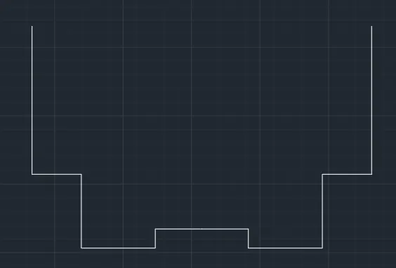
- command : line
- enter the first point : click on the end point of the 9' line on the right hand side
- enter the second point : @-3',0
- enter the next point : @4'2"<240(calculate the length = 3.6/cos30)
- enter the next point : @4'2"<120
- enter the next point : move the cursor from the bottom mid point of the bottom center line to thr top of the picture it indicates the intersection point and click on the point
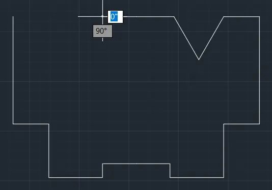
- enter the next point : in the same way move the cursor from the bottom end point of the 1'2"vertical line to the top of the picture ,it indicates the intersection point and click on the point
- enter the next point : @3'9"<225(calculate the length = 2.67/cos45)
- enter the next point : @3'9"<135
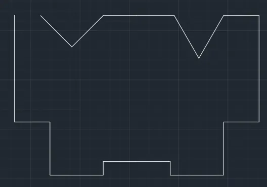
- and click the starting point of the picture to close the object
- to draw the quadrilateral inside the picture ,first draw it outside of the picture and later we put it inside the picture
- command : rectang
- enter the corner point : click on any point on the screen
- select the dimensions option
- enter the length :3' and enter the breadth :3'
- command : rotate
- select the rectangle
- specify the base point : select the bottom corner point of the rectangle
- specify the rotate angle : 45
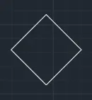
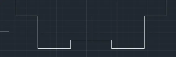
- command : line
- enter the first point : select the mid point of the bottom horizonatl line
- enter the second point : @0,3'4"(calculate the length = 4'6"-1'2"=3'4")
- command : move
- select objects : select the rectangle
- specify the base point : select the geometric center of the rectangle
- specify the second point : select the end point of the vertical line drawn previously
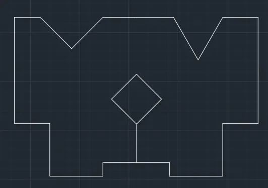
- command : erase
- select the vertical line of 3'4" drawn
- press enter
RESULT: