Creating a Floor plan, Footing detail and Isometric view using AutoCad
C-1:
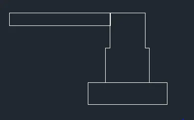
AIM: To create footing using AUTOCAD
PROCEDURE:
TO CREATE SUBSTRUCTURE:
- Command : RECTANG
- Specify first point as 1,1 and other corner point @0.90,0.25
- Command : POLYLINE
- Specify first point as 1.20 , other point as (@0,0.40), specify other point as (@0.05,0) ,specify other point as (@0,0.40) ,specify other point as (@0.40,0), specify other point as (@0,-0.40), specify other point as (@0.05,0), specify other point as (@0,-0.40).
TO CREATE SLAB FLOOR:
- Command : RECTANG
- Specify first point as any point (consider 2,2) and other corner point as (@1.15,0.15).
- To create complete substructure select MOVE option from modify.
- Select the drawn rectangle
- Select the basepoint : 2,2 and press ENTER.
- Select the basepoint on the top edge of the substructure and press ENTER
- Now the complete substructure is created.
TO CREATE SUPERSTRUCTURE:
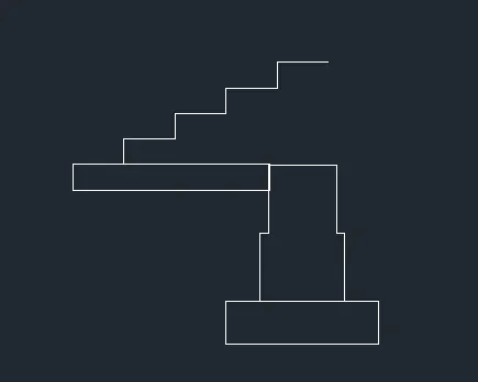
- Command : PLINE
- Specify first point 2,2 and other point (@0,0.15) and other point (@0.30,0)
- And again specify next point as (@0,0.15) and other point as (@0.30,0) and create 2 more steps with same measurements
- And move this steps portion by selecting MOVE option from the ribbon bar
- specify the basepoint as 2,2 and click the substructure on the point suitably as shown in the picture below
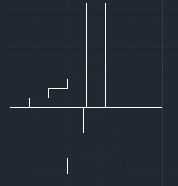
- Command : line
- Specify first point by clicking on the top edge of the step
- Specify next point : @-0.60,0 and other point as (@-0.30,0)
- Again Command : line
- Specify first point clicking on the last point in the previous picture and other point as (@1.15,0) ; other point as (@0,0.60) and the other point as (@-1.15,0)
- Command : line
- Specify first point on the end point and other point as (@0,1.05);other point as (@-0.30,0) and other point as (@0,-1.15)
- To create damp course :
- Command : line
- Specify point : 2.90,2.60
- Specify next point : @0.30,0
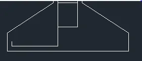
- And the result is shown in below.
RESULT:
C-2:
AIM: To create ISOLATED FOOTING using AUTOCAD
PROCEDURE:
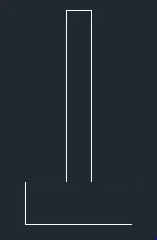
- Command : PLINE
- Specify first point : 1,1
- Specify next point : @0,0.40 [here 0.40=0.15+0.25]
- Specify next point : @0.38,0
- Specify next point : @0,1.60
- Specify next point : @0.24,0 [here 0.24=1.00-(2*0.38)]
- Specify next point : @0,-1.60
- Specify next point : @0.38,0
- Specify next point : @0,-0.40
- And the select close.
- Now select CHAMFER option from the ribbon bar
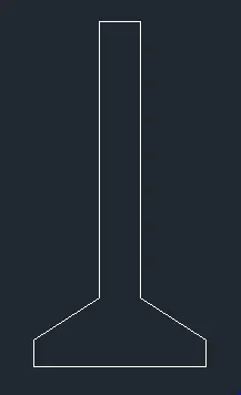
- Select first chamfer line : click on the vertical line
- Enter first chamfer distance : 0.25
- Enter second chamfer distance : 0.38
- And do it on the opposite side also and we get the result as shown in below
- To create footings
- Command : PLINE
- Specify first point : 1.42,3
- The point mark at the top the footing
- Enter second point : @0,-0.20
- Enter next point : @0.16,0
- Enter next point : @0,0.20
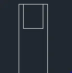
- It is created like this at the top
- Now copy the small rectangle
- By selecting COPY from ribbon bar
- Select the small rectangle
- Enter the basepoint : click on one edge of the rectangle
- And copy 8 such rectangles in downward direction
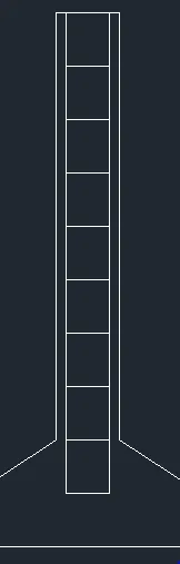
- Command : PLINE
- Specify first point : click on the left bottom edge of the small copied rectangles
- Enter next point : @0,-0.16
- Enter next point : @-0.38,0
- Enter next point : @0,0.04
- In the same on the right hand side of the footing is also created
- Command : PLINE
- Specify first point : click on the other of the footing
- Enter next point : @0,-0.16
- Enter next point : @ 0.38,0
- Enter next point : @ 0,0.04
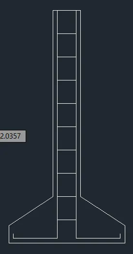
- Final output is shown in the result
RESULT:
C-3:
AIM: To create LINE DIAGRAM OF TWO BEDROOM BUILDING
PROCEDURE:
TO CREATE OUTLINE OF THE BUILDING:
- Command : LINE
- Enter first point : 1,1
- Enter next point : @0,4.20
- Enter next point : @-0.90,0
- Enter next point : @0,1.00
- Enter next point : @0.90,0
- Enter next point : @0,3.60
- Enter next point : @3.60,0
- Enter next point : @0,-3.60
- Enter next point : @0.90,0
- Enter next point : @0,-1.00
- Enter next point : @-0.90,0
- Enter next point : @0,-4.20
- And then click CLOSE.
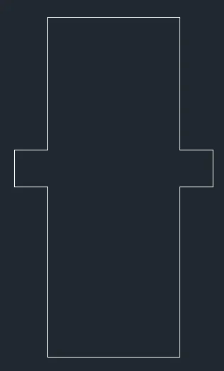
- The resultant is shown in the figure below.
- TO CREATE LINES INSIDE THE ROOMS :
- Select OFFSET from ribbon bar
- Select the left side line of the room and click on the right side of the line
- And again click on the right side of the line
- Such that two lines are created
- In the same way the either side the lines in the room are created
- TO CREATE DIVIDE WALL OF BEDROOM AND LIVING ROOM:
- Command : LINE
- Specify first point : Click on the left edge of the bedroom where the wall is to be created
- Enter next point : @0.90,0.
- Command : LINE
- Specify first point : click on the other side bedroom point where the wall is to created
- Enter next point : @-1.80,0
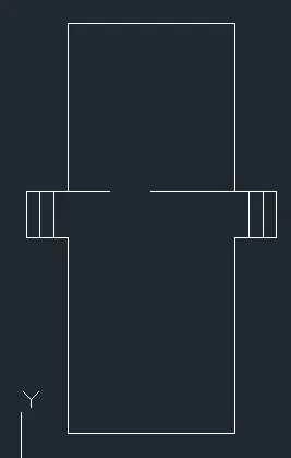
- Finally the divide wall is created as shown in the figure below.
RESULT:
C-4:
AIM: To create C.S OF LOAD BEARING WALL SHOWING FOUNDATION DETAILS
PROCEDURE:
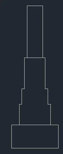
TO CREATE SUBSTRUCTURE:
- TO CREATE FIRST STEP:
- Command : RECTANG
- Specify first point : 1,1
- Specify next point : @0.90,0.45
- The first step created as shown in figure below.
- TO CREATE NEXT THREE STEPS:
- Command : PLINE
- Specify first point : 1.15,1.45
- Enter next point : @0,0.40
- Enter next point : @0.05,0
- Enter next point : @0,0.30
- Enter next point : @0.05,0
- Enter next point : @0,0.60
- Enter next point : @0.05,0
- Enter next point : @0.30,0
- Enter next point : @0.05,0
- Enter next point : @0,-0.60
- Enter next point : @0.05,0
- Enter next point : @0,-0.30
- Enter next point : @0.05,0
- Enter next point :@0,-0.40
TO CREATE LOAD BEARING WALL:
- Command : PLINE
- Specify first point : click on the top the last step
- Enter next point : @0,1.00
- Enter next point : @0.30,0
- Enter next point : @0,-1.00.
- The total output is shown in below
RESULT:
C-5:
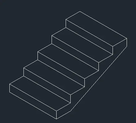
AIM: To create ISOMETRIC VIEW OF STEPS
PROCEDURE:
- Select ISOMETRIC and ORTHO options from DS settings.
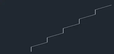
- Command : PLINE
- Specify first point : 1,1
- Select ISOMETRIC RIGHT in the isometric draw down
- Enter next point : keep the cursor in the upward direction and enter 0.15
- Keep the cursor in right side direction and enter 0.30
- Again keep the cursor in the upward direction and enter 0.15
- Keep the cursor in the right side direction and enter 0.30
- Repeat the same procedure and create 5 steps
- Change ISOMETRIC LEFT in the isometric draw down
- Command : LINE
- Specify first point : click on the edge point of tread
- And keep the cursor in the inclined direction and enter 1.00
- Command : LINE
- Specify first point : click on the other edge point of the tread
- And keep the cursor in the inclined direction and enter 1.00
- Repeat the above procedure for all the steps

- Select ISOMETRIC RIGHT
- Command : PLINE
- Specify first point : click on the starting point o the step and let it be bottom point of the steps
- Keep the cursor in the upward direction and enter the next point :0.15
- Keep the cursor in the inclined direction and enter 0.30
- Keep the cursor in the upward direction and enter the next point :0.15
- Keep the cursor in the inclined direction and enter 0.30
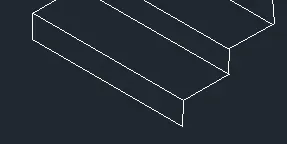
- Repeat the above step to the top edge of the steps and the resultant is shown below.
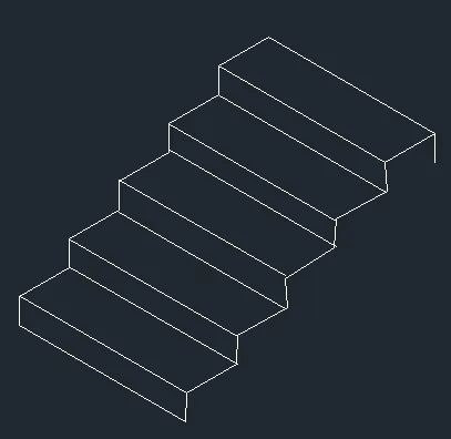
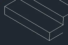
- To create string base of the steps :
- Command : LINE
- Specify the first point : click on the bottom step
- Keep the cursor in the inclined direction and enter 0.30
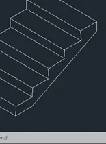
- Put off the ORTHO and ISOMETRIC options
- Command : LINE
- Enter first point : click on the end of the previous drawn line
- Specify next point : click on the top step of the stairs to complete the picture
RESULT:
C-6:
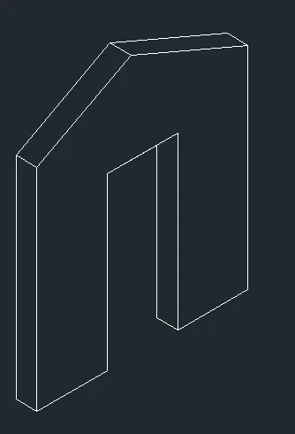
AIM: To create ISOMETRIC VIEW OF GABLE WALL
PROCEDDURE:
- Select ORTHO and ISOMETRIC options from DS settings
- Select the ISOMETRIC RIGHT option from isometric draw down menu
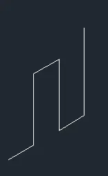
- Command : LINE
- Specify first point : 1,1
- Enter next point : keep the cursor in the inclined direction and enter 1.00
- Keep the cursor in the upward direction and enter 2.42
- Keep the cursor in the inclined direction and enter 0.7
- Keep the cursor in the same direction and enter 0.30
- Keep the cursor in the downward direction and enter 2.42
- Keep the cursor in the inclined direction and enter 1.00
- Keep the cursor in the upward direction an enter 3.00
- We’ll get figure as shown the figure below
- Change to ISOMETRIC LEFT
- Command : Line
- Specify first point : click on the starting point of the wall where we started to draw
- Keep the cursor in the inclined direction and enter 0.30
- Keep the cursor in the upward direction and enter 3.00
- Keep the cursor in the inclined direction and join the wall
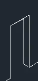
- Command : line
- Specify first point : click on the door bottom point
- Keep the cursor in the inclined direction and enter 0.30
- Keep the cursor in the upward direction and click on the top of the door
- Command : LINE
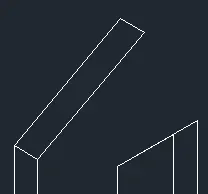
- Specify first point : click on the top edge point of the wall where we start to create roof
- Put off the ORTHO and ISOMETRIC
- Calculate the roof length = 1.80 hence pythagorous theorem
- And also calculate the angle made by the roof with horizontal
- Keep the cursor in the right side and enter @1.8<60
- In the same way the other edge of the selected and command : line
- Draw the line by entering @1.8<50
- Now create the other side of the roof
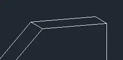
- Command: line
- Specify the first point : click on the point other side of the roof
- Enter next point : @0.30<130

- Now join the lines to the top of roof
RESULT: