Door Trim Lower with Engineering Features
WEEK 10 CHALLENGE 3 : DOOR TRIM LOWER WITH ENGINEERING FEATURES
AIM :
Create the Door Trim Lower Plastic component through the given Class-A surface. To begin with, the tooling axis for the given Class-A Surface should be created meeting the requirements of the draft angle and at the end perform the Draft analysis on the model.
DOOR TRIM PLASTIC COMPONENTS :
- FOUR WAY LOCATOR : locators are used to locate the component accurately in its position on the other component. four way locators does this job and in addition, it arrests the freedom of the component in 4 direction and and 2 axes (X+,X-,Y+ and Y-).
- TWO WAY LOCATORS : helps to locate and arrests freedom of component in 2 direction and 1 axis.
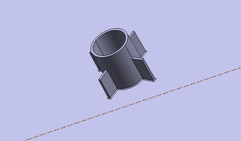
- HEAT STAKES : Heat staking is a process of joining two plastic components by heating. it is a kind of plastic welding. drafted plastic projections on one component aligns with the hole provided on the other and by enabling localised heating,plastic reforms and a strong bond is acheived.this drafted cylindirical projections are called heat stakes. Heat stakes should be designed inferior in projection height to locators,because locators should be the one comes first in contact with the secondary component while joining.
TOOLING AXIS CREATION :
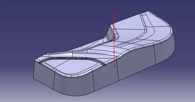
Tooling axis is the direction in which mould travels. basically there are two pieces for mould,one cavity side and one possess projections of the component. the draft angle given for the component for ease of ejection, is drafted with reference to this tooling axis.
conducted visual inspection initially, then checked for,if there is any gaps or corrections by taking boundary of the component.placing tooling axis perpendicular to the largest flat area of the component is more convenient for manufacturing. for the given surface , due to its shape and design it would be more convenient to manufacture if the tooing axis in Z direction. so extracted a surface from the largest face of the given class A and placed a point on middle of the surface.created axis through this point perpendicular in direction.
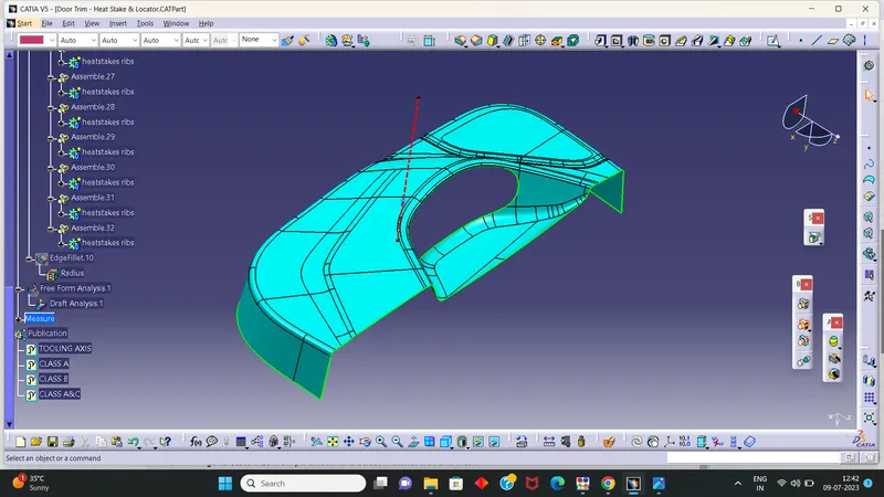
DRAFT ANALYSIS ON CLASS A
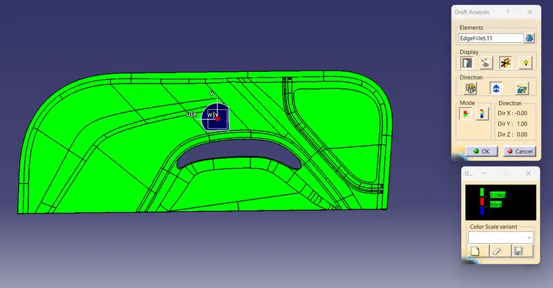
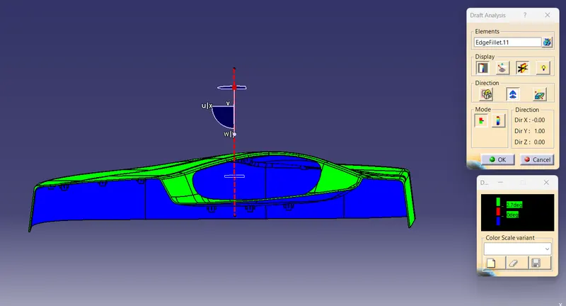
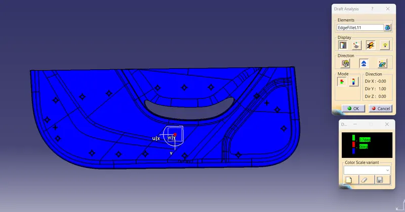
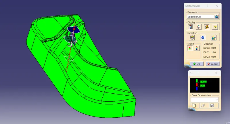
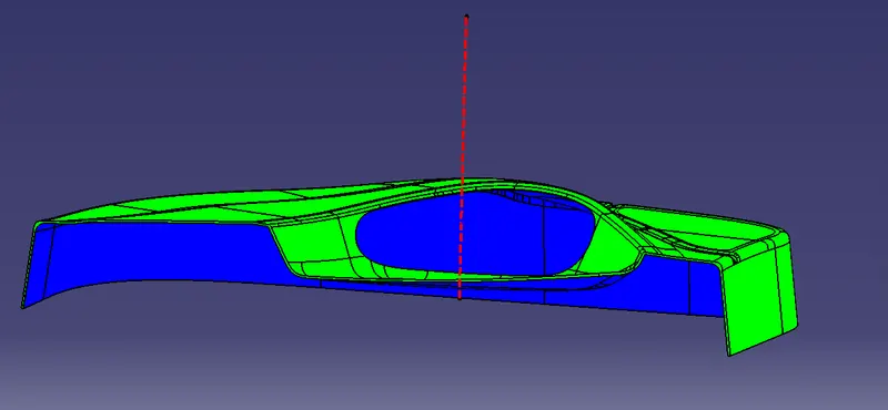
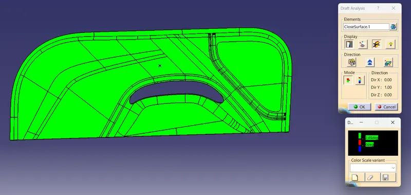
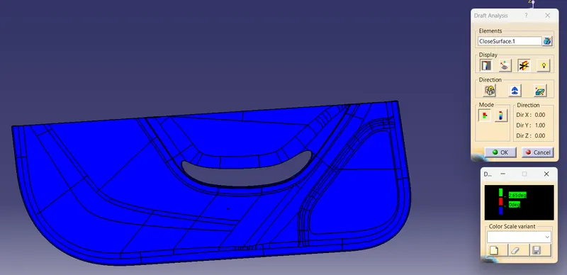
By performing draft analysis on the given class A surface enables to know wheather the component is easily removable or not and the tooling axis which we created is apt for manufacturing . this analysis is based on colour ranges which indicates different colours for different angles.
- go to customize view parameter and select material mode in mesh
- select feature draft analysis from analysis option by going in insert option from tool bar
- place the compass align to tooling axis with the help of compass tool
- select the surface
- click display button on the window
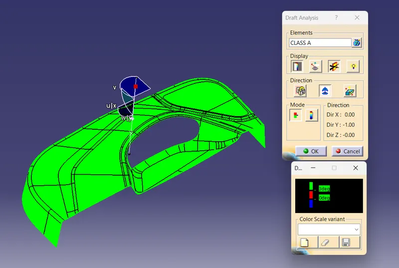
each colour zones indicates each drafting angles,green indicates within given draft angle , red indicates zero and blue indicates negative angle
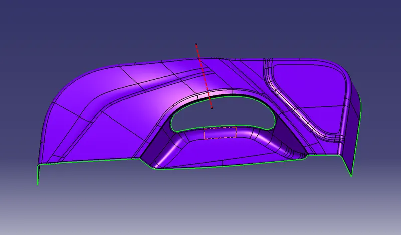
CREATION OF CLASS B SURFACE
start with creating seperate geometrical set for class b, take an offset of the given class surface to a value of 2.5mm in inside direction. some patches would be there in the offsetted plane,most of the times,fillets are the cause of patches.
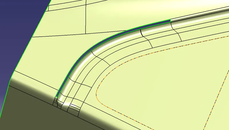
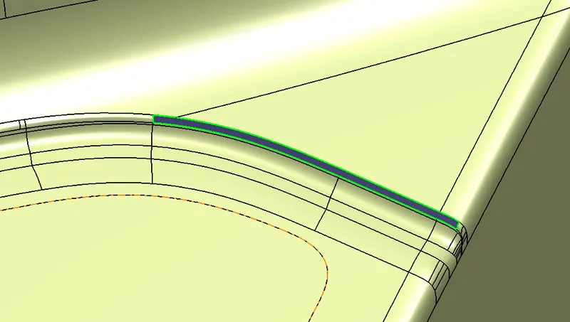
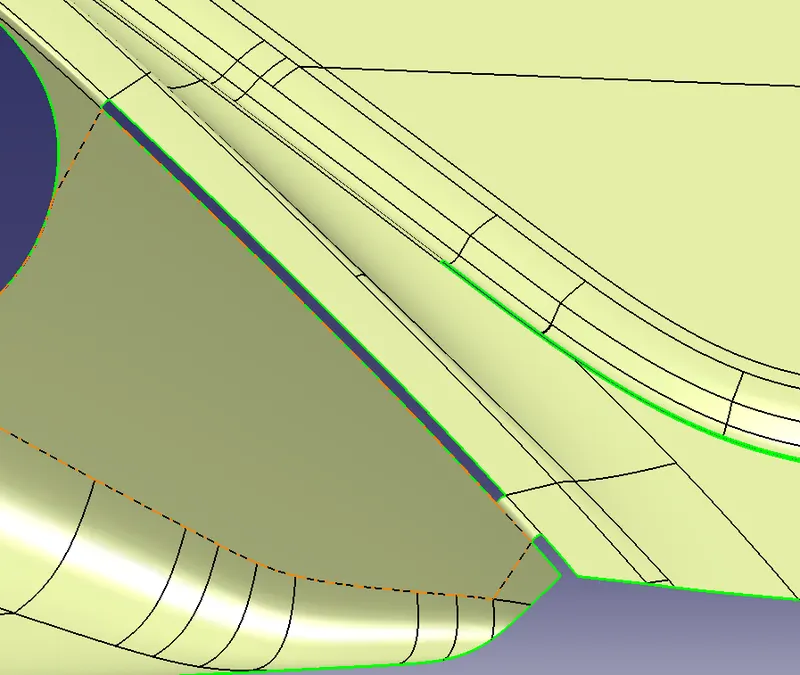
extract surfaces on the sides of each patch,extrapolate them and trim
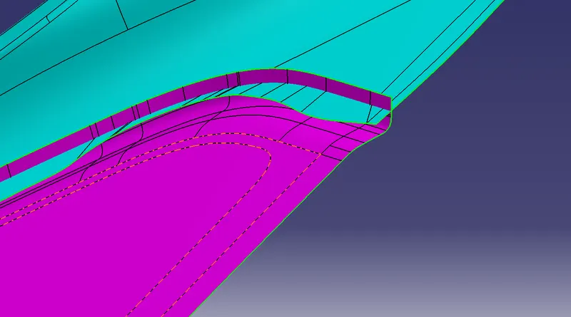
perform the same for every patch.
provide fillets to trimmed joints to obtain class B surface
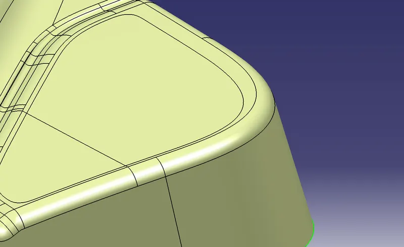
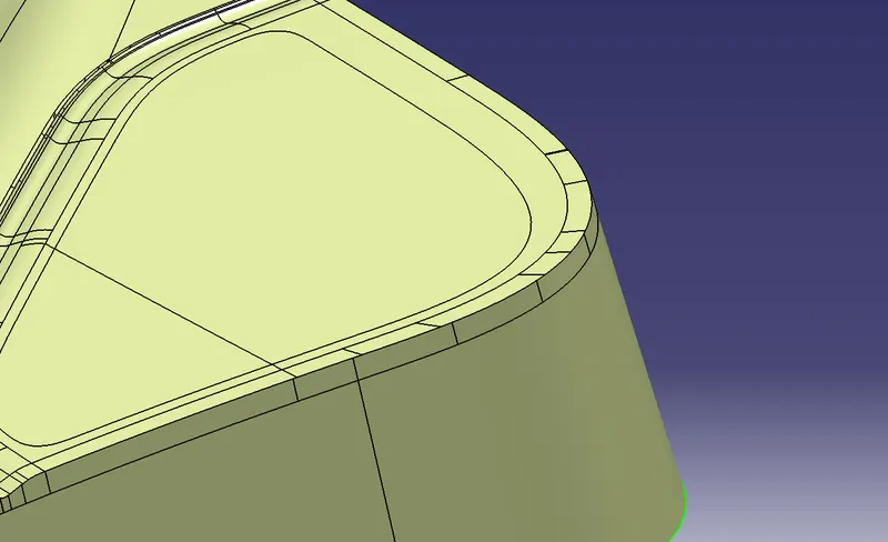
CLASS B SURFACE
CLASS C CREATION:
- create boundaries at edges of class a
- select sweep with draft direction from sweep option.
- select the created boundary as guide curve and tooling axis as draft direction,with 3 degree angle projecting out from class a
- follow above sweep procedure for planes which are perpendicular to tooling axis
- for planes parallel to axis,sweep in 90 degree refence to the class a surface
- extrapolate the ends of swept planes and trim altogether to get the c surface
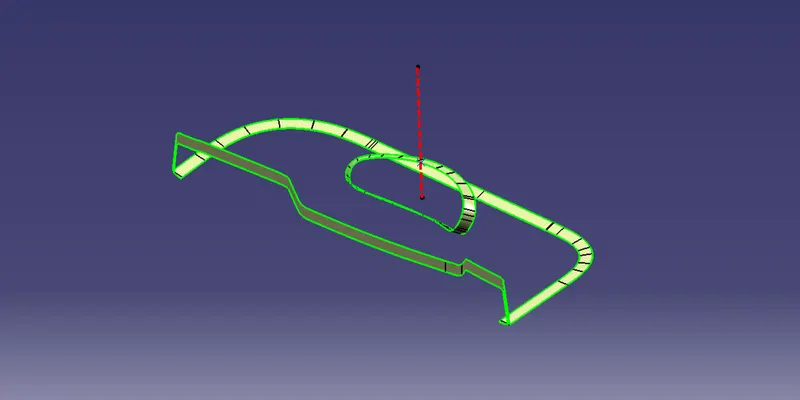
always remember to give a 1 mm of second limit when sweeping,because it helps class c to trim properly with class a.
CLASS A & C
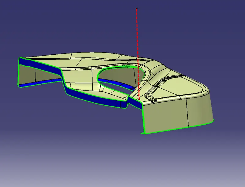
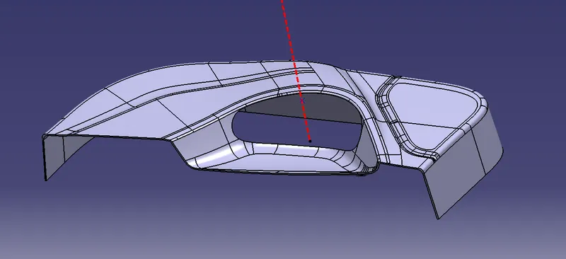
trimming class A,B & C gives final closed body
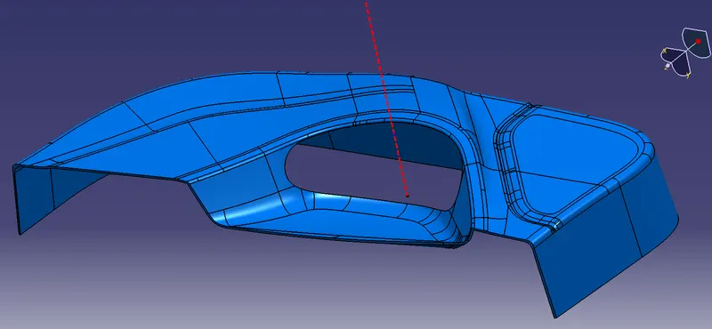
moving to part workbench, opting closed body tool and selecting our final trim obtains solid body
DRAFT ANALYSIS ON SOLID COMPONENT :
CONSTRUCTION OF FOUR WAY LOCATORS:
- created a plane perpendicular to the tooling axis on reference to the point on the tooling axis.
- opened a positioned sketch with reference to the new plane and point
- drew 2 lines perpendicular to each other where the locater is desired to be placed
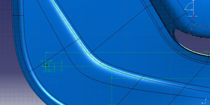
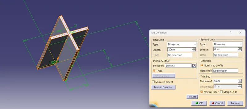
- chose pad tool from part workbench and padded upto desired height and provided a min value as second limit to ensure proper joining with partbody
- selected "thick" option from window of pad tool and provided desired thickness in neutral fiber
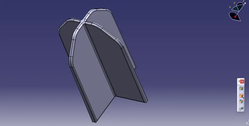
- drafted the walls for a value of 0.5 degree in tooling axis direction
- chamfered the top four edges of the padded object to a value of 45 degree
- filleted chamfered edges with 3 degree
- filleted remaining edges with .25 degree
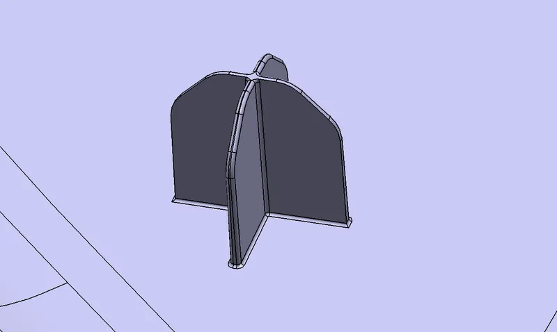
- with the help of translation tool,translated a copy of the four way locater to the point which created on the body where other locater has to be placed.
- union trimmed with part body by selecting the projection of locators on the other side as faces to remove
CONSTRUCTION OF HEAT STAKES :
- pointed the positions on the solid body where the heat stakes to be placed on
- created a positioned sketch on reference to the same plane and point used earlier.
- drew 2 concentric circles on one of the point as centre,of desired diameters
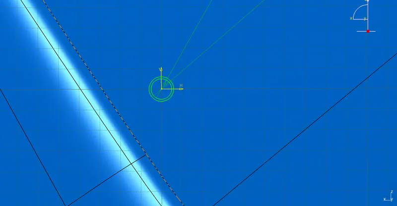
- pad the circles in part workbench to desired value with a min secondary length.
- draft the inside and outside wall of the heatstake to a value of 0.5 degree with tooling axis
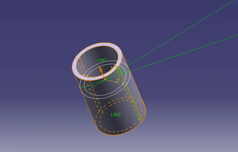
- copy the part and paste special > result with link
- translate the duplicate with translation tool to the next point
- repaet the same till last point
- select all the duplicate part bodies and select assemble to a new body
- union trim this body with main part body as selecting unwanted parts as faces to remove
- give fillet to the edges
CONSTRUCTION OF HEAT STAKE RIBS:
- opened a positioned sketch on reference to the inputs given before for sketches
- drew mutually perpendicular lines on centre of the heatstake
- padded it in part work bench with thickness in neautrel fiber
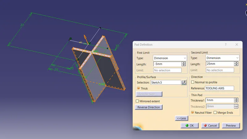
- drafted all the faces with respect to tooling axis and base as neutral element
-
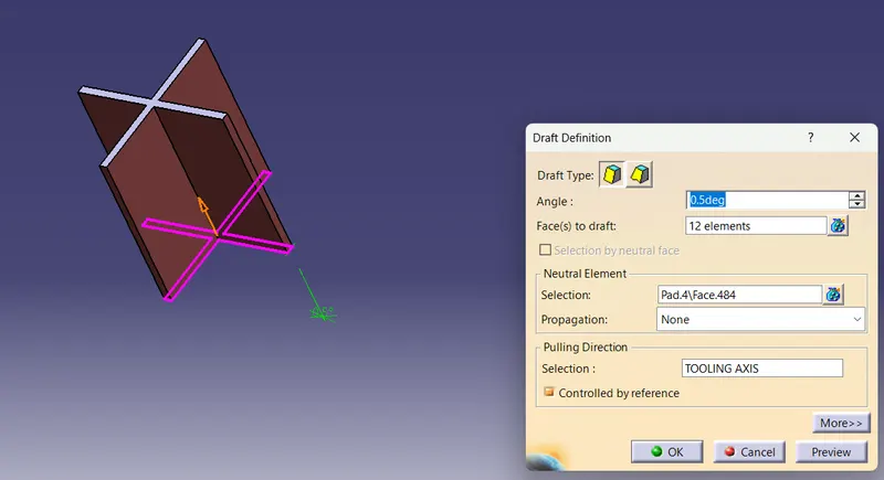
- copied the body and selected result with link from paste special to craete a duplicate
- translated the duplicate with translation tool to the centre point of the next heat stake
- continued the same for all heat stakes
- assembled all the bodies into a new body
- union trimmed this new body to the main part body as selecting the unwanted faces as the body inside the heat stake and projections on the other side
- give fillet to the edges
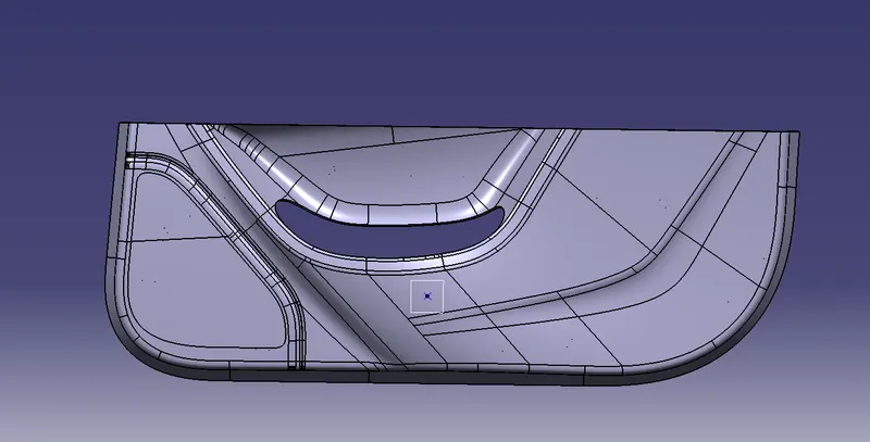
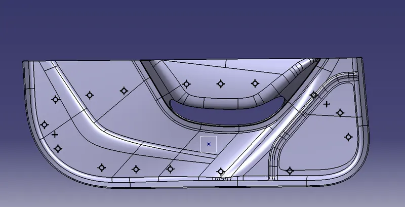
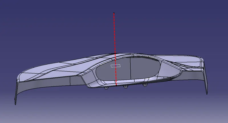
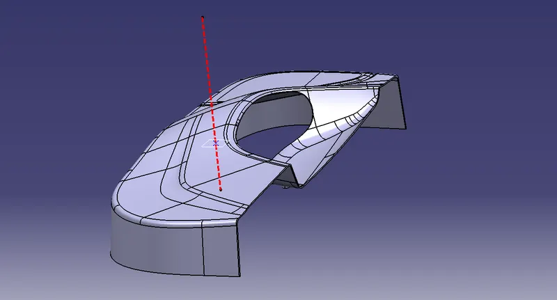
DIFFERENT VIEWS OF FINAL SOLID PART:
DRAFT ANALYSIS ON FINAL SOLID COMPONENT: