Door Arm Rest Week 8 Challenge
The draft analysis of the door arm rest can be made by considering the following points.
Firstly we need to check the boundary conditions of the door arm rest component which shows it is single boundary condition.
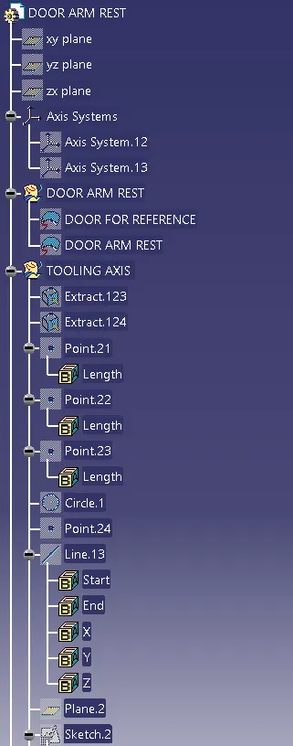
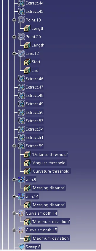
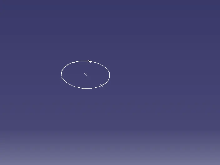
For to create tooling direction of the door arm rest component which can be done by using the circle by 3 points on base circle component.
we have to select three points on a circle which allows to create a circle by joining all three components.
The line can be constructed on point by which we have considered to create a circle by 3 points, which is main tooling direction.
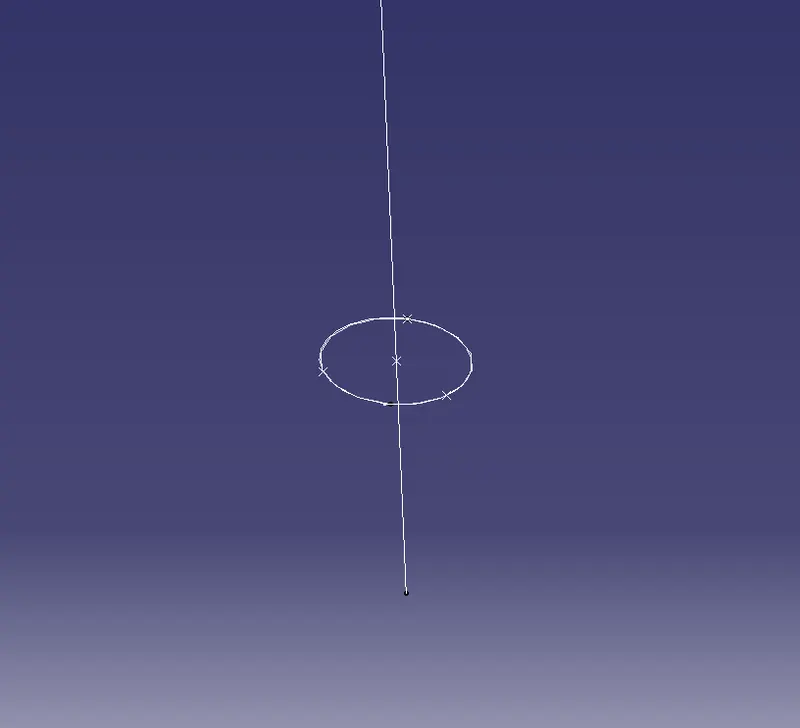
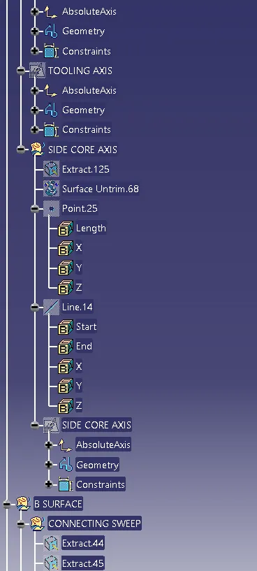
Like in the same way we have to create a side core tooling axis with the same point which we have considered for the creation of main tooling direction which will helpful for the draft analysis of the side core component of the door arm rest component.
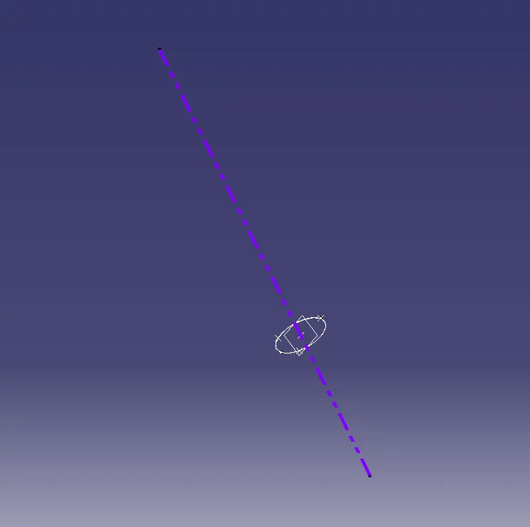
By extractig the side core component of the door arm rest component we can extract the surface and untrim the extract and make a line on it by creating a plane surface which gives a side core toooling directon.
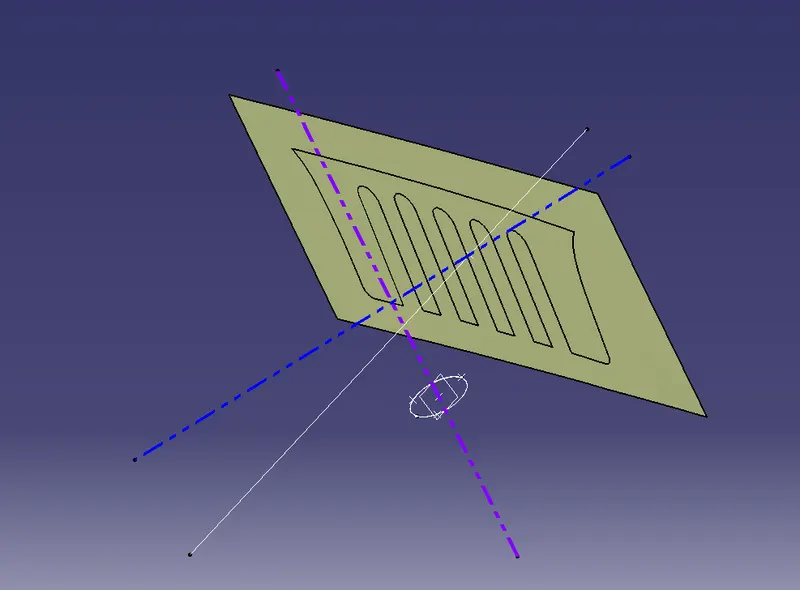
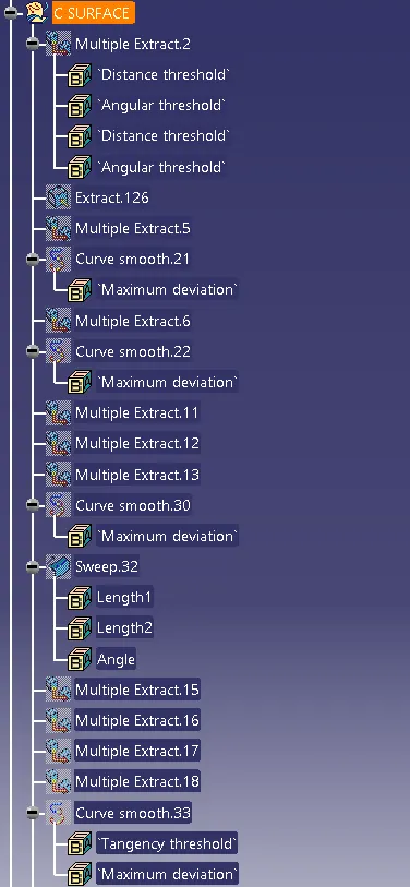
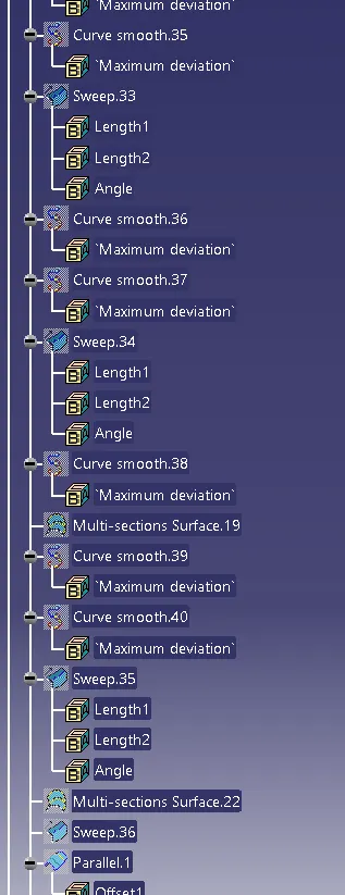
The connecting sweep can be made by considerig the side position the curved component which is curve with some angle position which can be done by creating a line on it extract the component and untrim the component and extrapolate the component which gives a proper dimensions of the side core axis.after sweeping the component we need to join the component which does not shows a single patch on the surface.
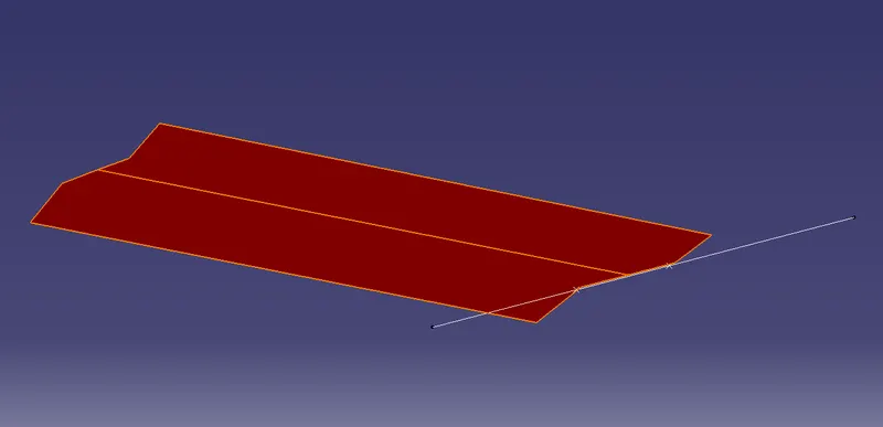
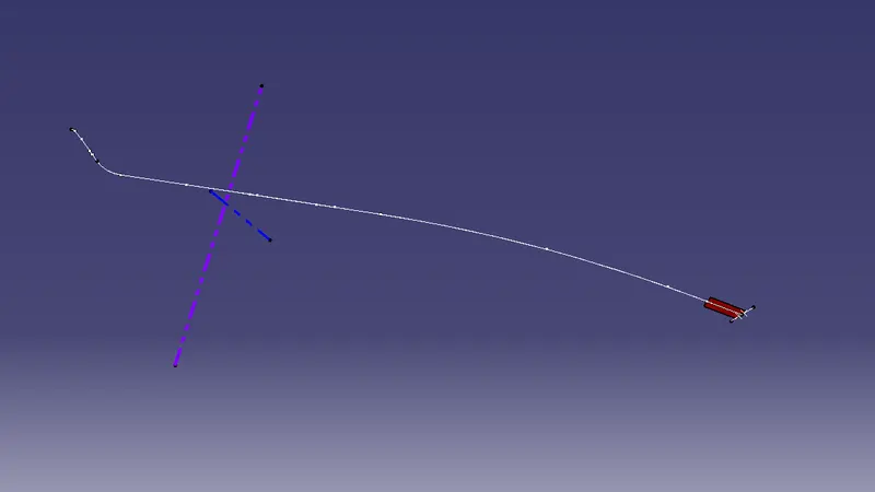
after making the smooth curves we should sweep the components by adding together in which they are joined together to give a proper shape of the component.
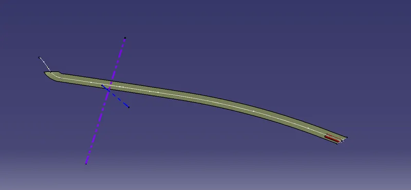
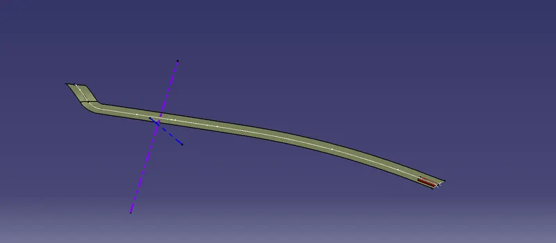
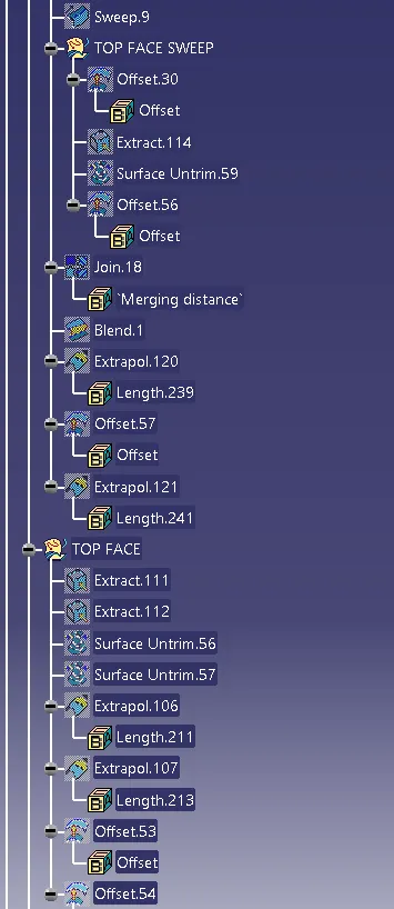
After this sweep the outer surface and offset it to a distance of 2.5mm for the selected surfaces.
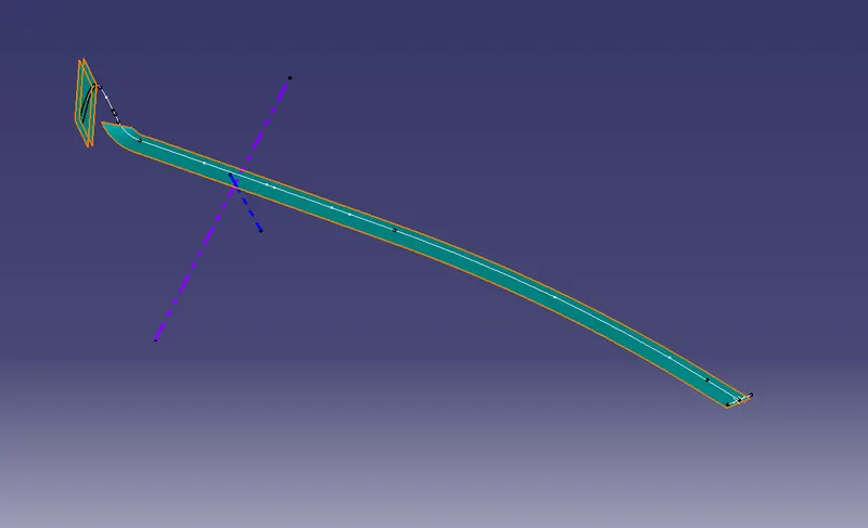
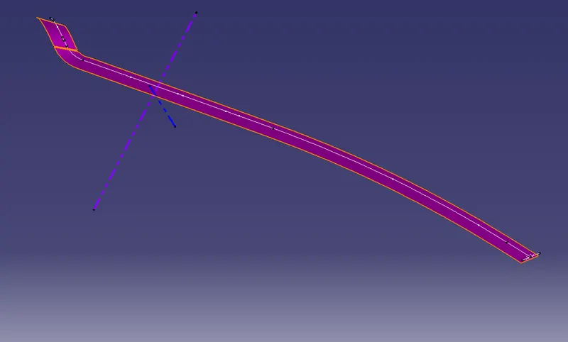
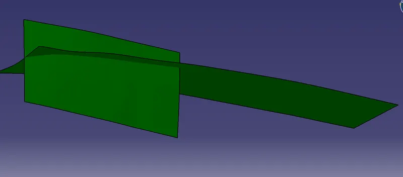
Extract the top surface and untrim the extracted component which gives a proper shape of the component and extrapolate the component and trim it of with which faces you required.
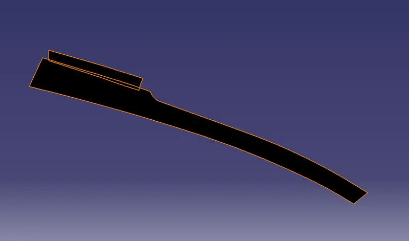
 .
.
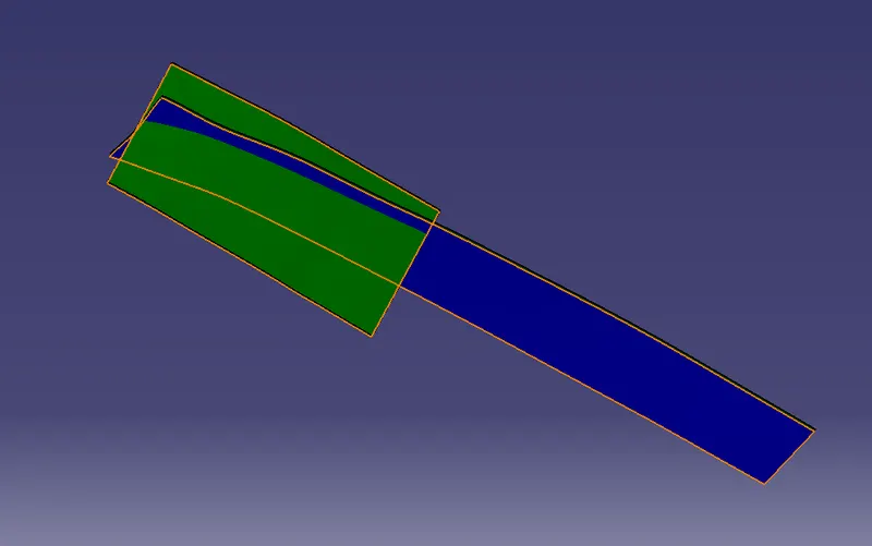
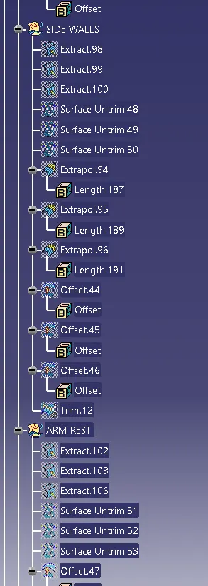
Same operations can be done on side walls of the component by selecting the proper areas to be covered and make extract of the component and untrim and extrapolate the untrim options and offset it to a distance of 2.5mm.
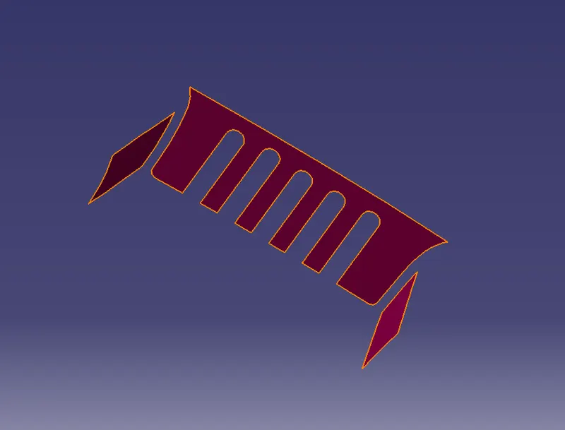
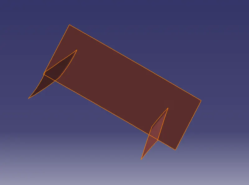
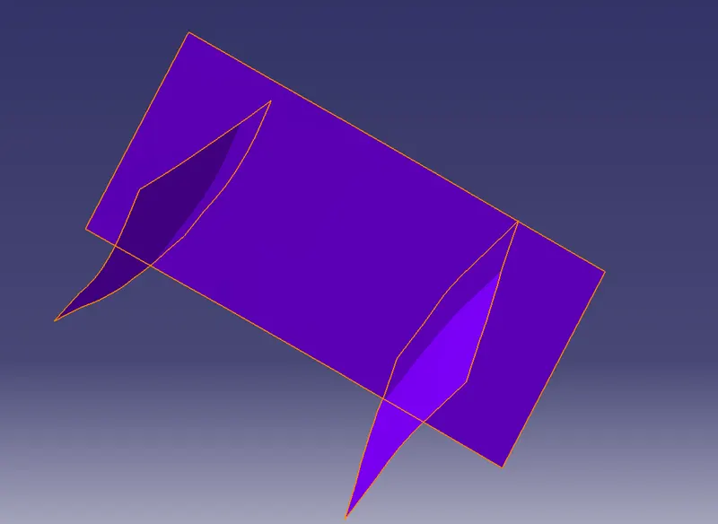
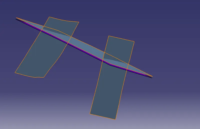
After applying the offset trim side walls by selecting the dimensions which we need and trim it off.
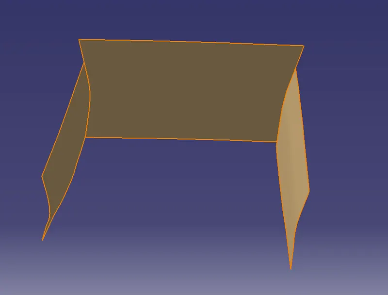
Consider the door arm rest of the component of the other side of the system and extract the component and untrim the component and extrapolate this surface and offset it a distance of 2.5mm from the extrapolate.
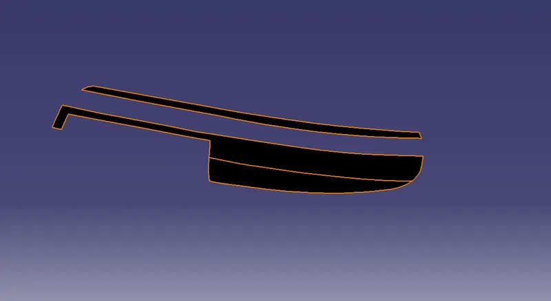
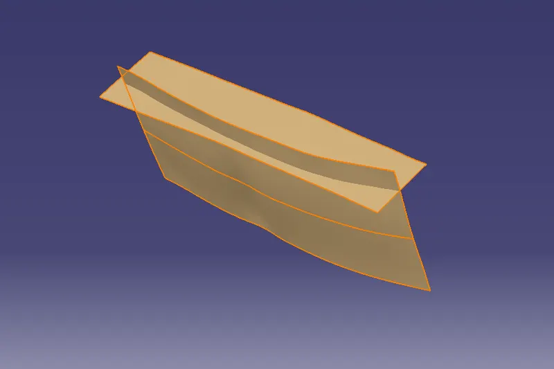
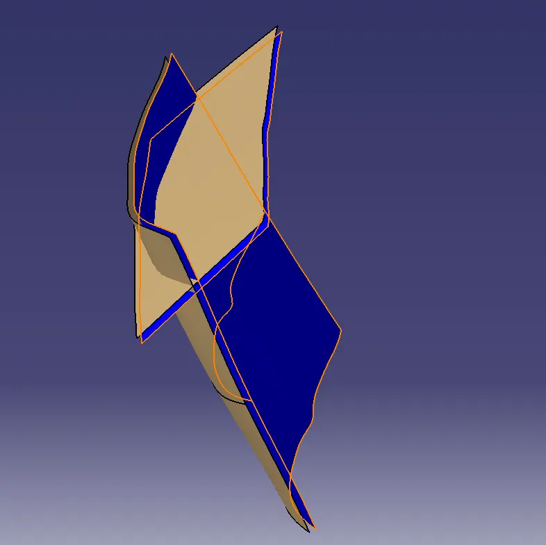
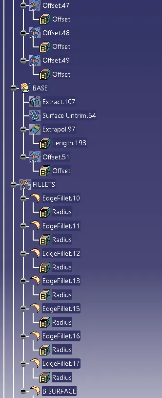
After applying the boundary conditions to the door arm rest of the component apply the same conditions to the base component and conduct the extract,untrim and extrapolate the comonent and make it offset to a distance of 2.5mm.
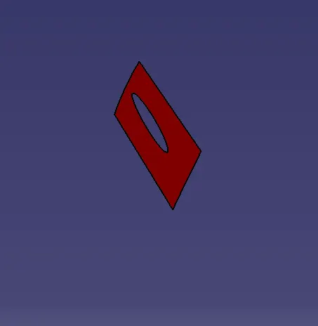
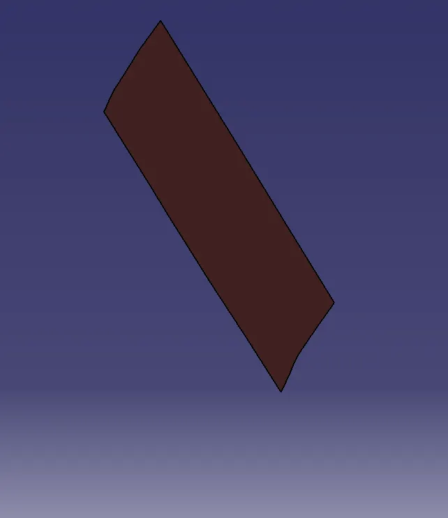
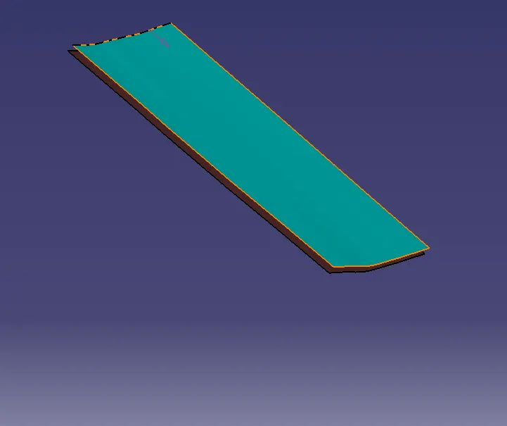
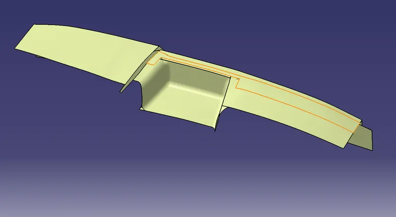
Apply the fillets at the edges to get a proper dimensions of the component and calculate the edge fillet radius and apply accordingly.
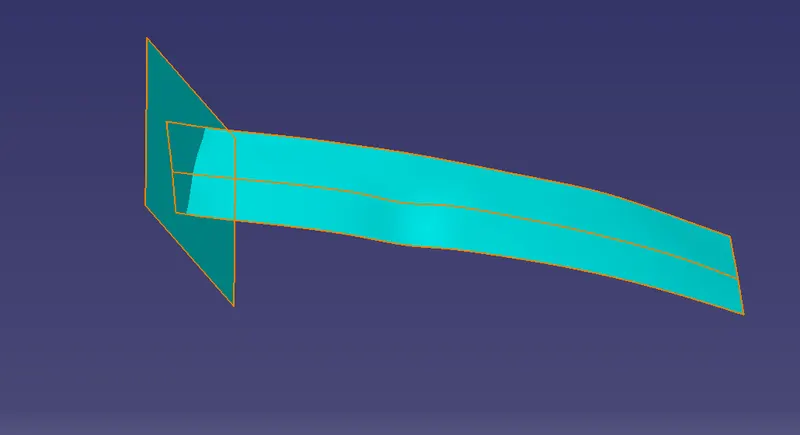
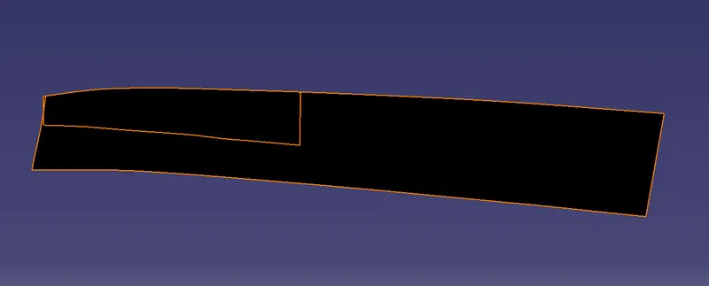
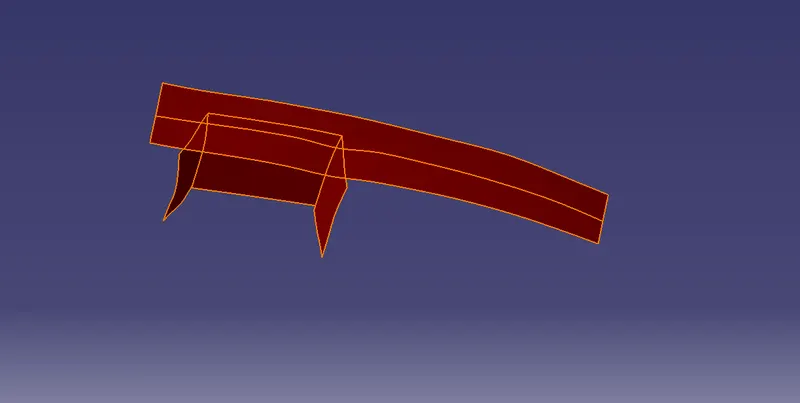
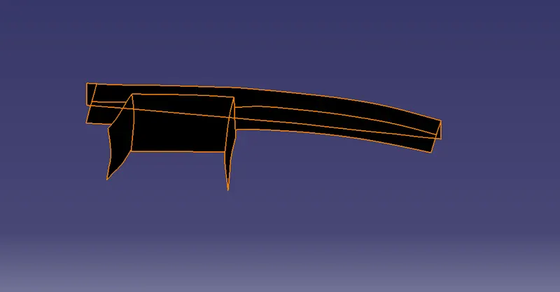
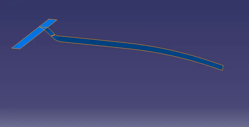
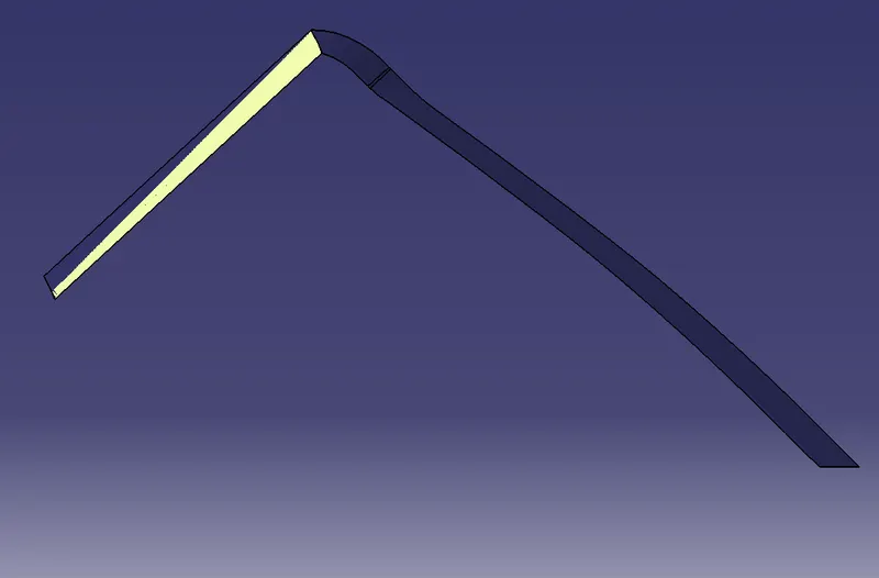
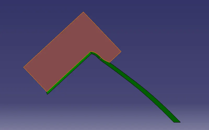
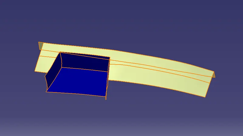
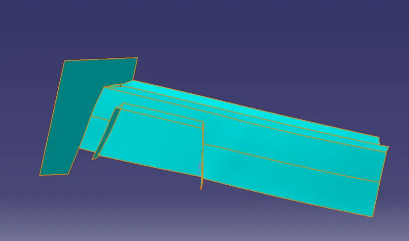
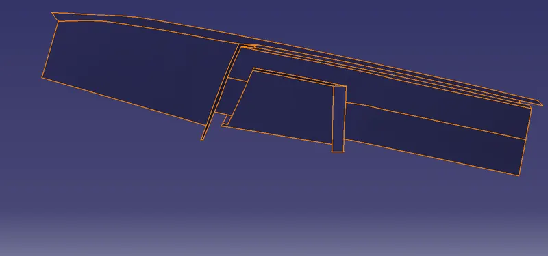
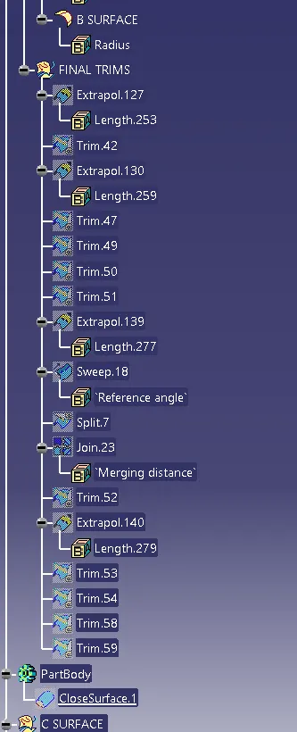
After applying the fillets and all do final trims for the surfaces which are at some distances and make trim of the component and make them together and keep the faces which you want and trimming the surfaces which are extrapolated and untrimming the surfaces then make a offset of the component.
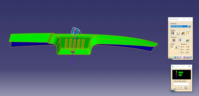
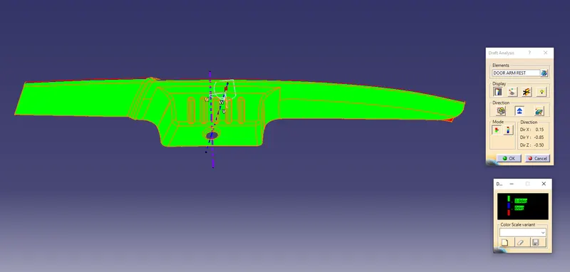
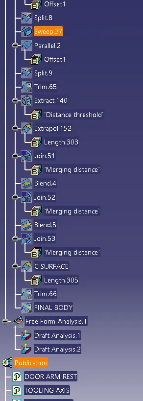
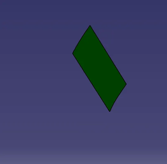
after joining the class A surface with a class B surface with a minimum thickenss of 2.5mm inside the two surfaces and make it a solid body of the component, and close the surfaces and perform the draft analysis of the component. which follows the draft angle direction and which shows the green color with a minimum draft angle of 2.9 degree to the component.
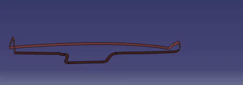
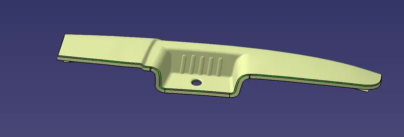
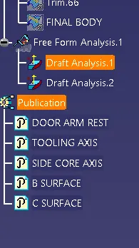
Publish class A surface and class B surface and class C surface and Main tooling direction and side core tooling axis of the component so to get them on a perfect time and make them so easily to work on it.