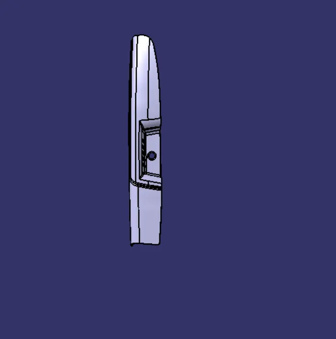
Door Arm Rest Week 8 Challenge
AIM
Creation of Door Arm rest and add thickness to it
OBJECTIVE
The door arm rest solid model with the design features involved and creation of the surface thickness necessary. Along with it considering the mould aspects and providing sufficient draft angle by the analysis tool to avail its feasibility.
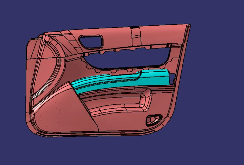
DOOR ARM REST
PROCEDURE
TOOLING AXIS CREATION
Creating a point on centre of the circle using point tool and an axis system created in that point.
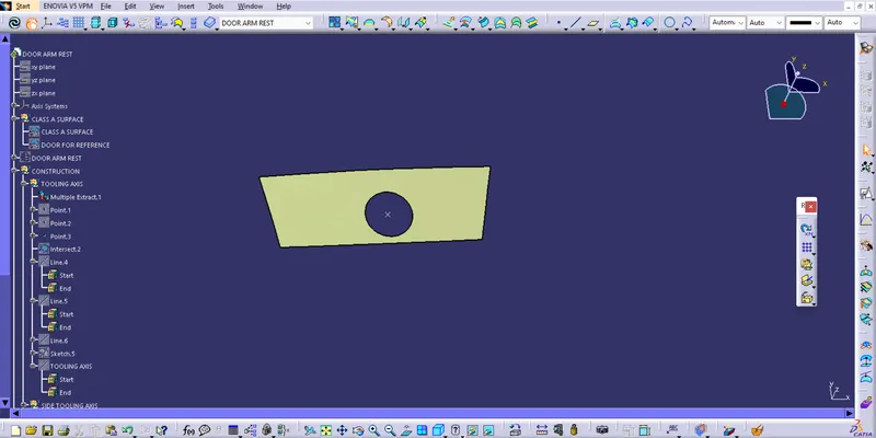
Intersection and extending side walls
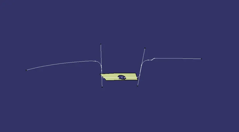
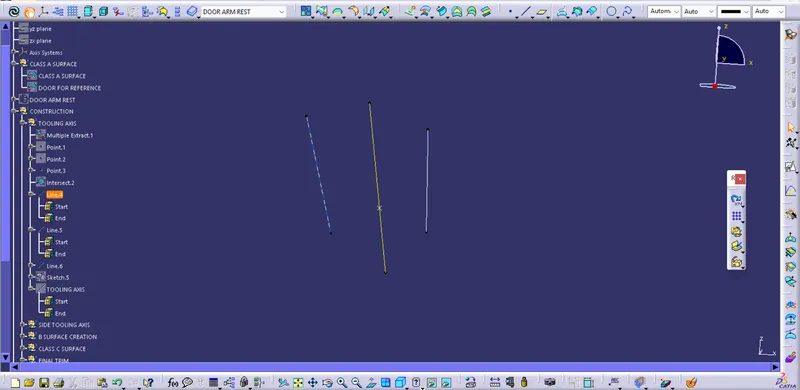
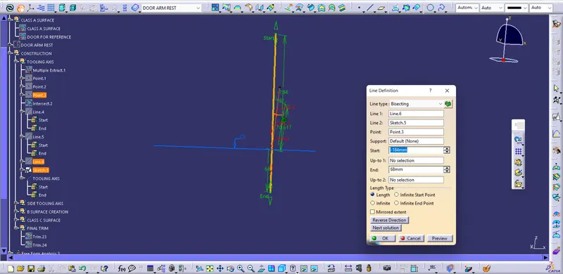
Tooling axis on x direction using line tool and bisectiing line type.
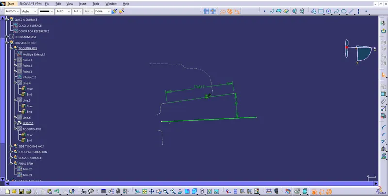
Tooling axis on y direction is created by drawing a sketch.
Tooling axis is created using x and y direction axis.
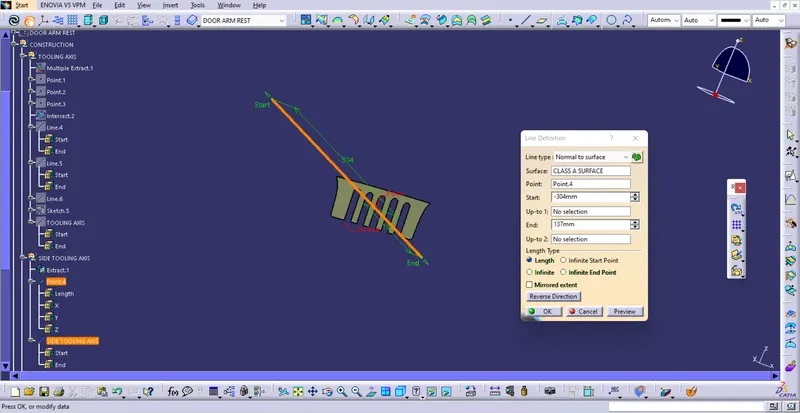
SIDE CORE TOOLING AXIS CREATION
Extracting surface and a point is marked on the center. A line is drawn perpenticular to the surface . It is the side core tooling axis.
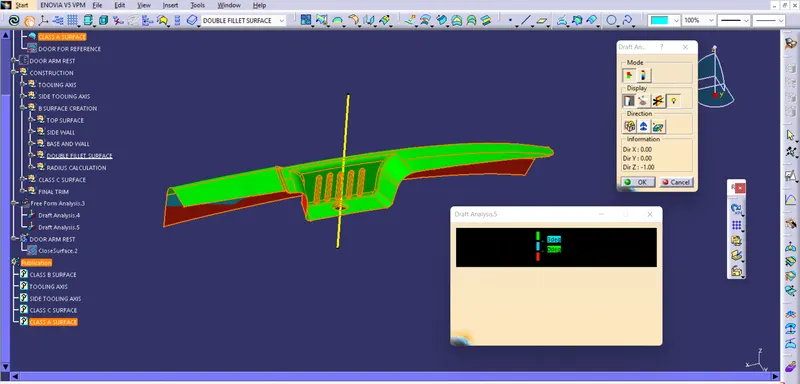
DRAFT ANALYSIS
Draft analysis report of Class A surface
B SURFACE CREATION
Exatracting top surface
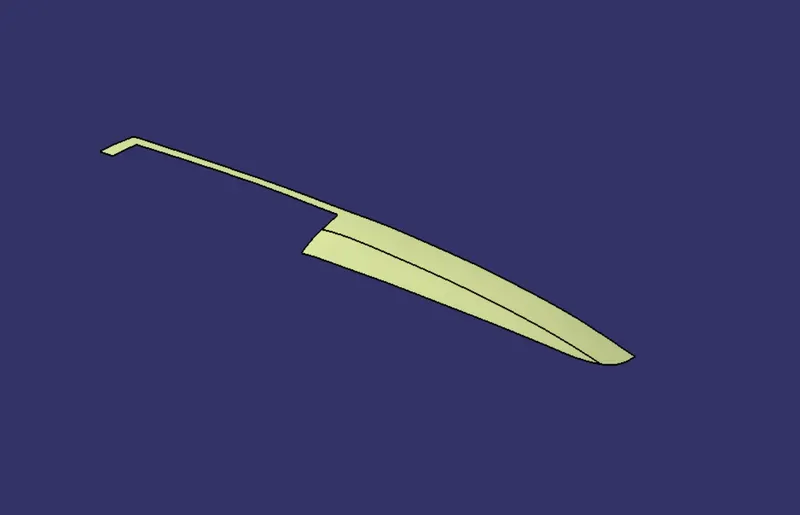
Extracted surface is untrimed and offset to 2.5 mm downward.
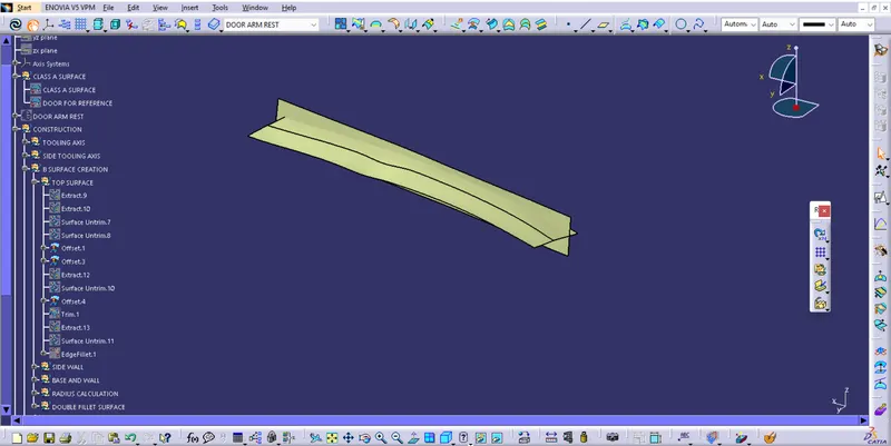
Trimed the surface and edgefillet is applied.
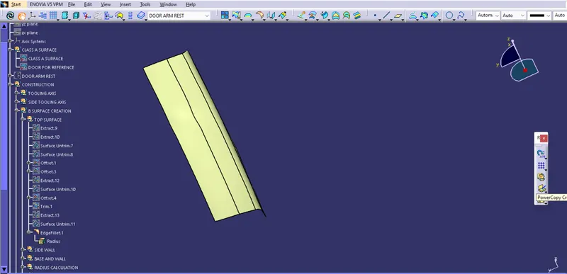
Extracting side walls
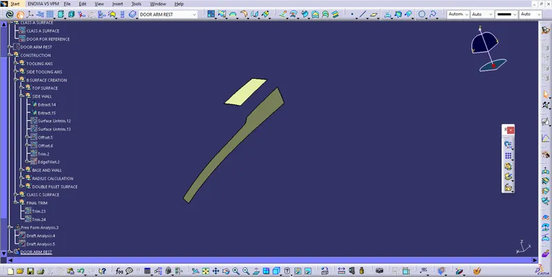
Untrim, offset, extrapolate, trim and edgefillet is done on the surface
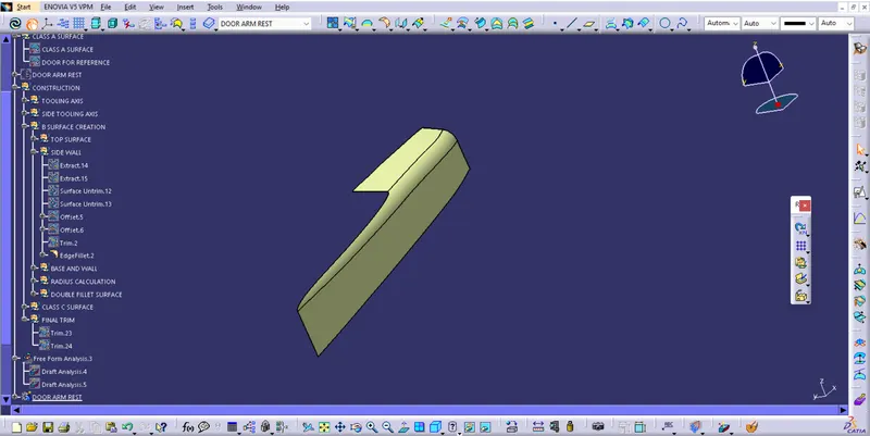
Base and walls are extracted
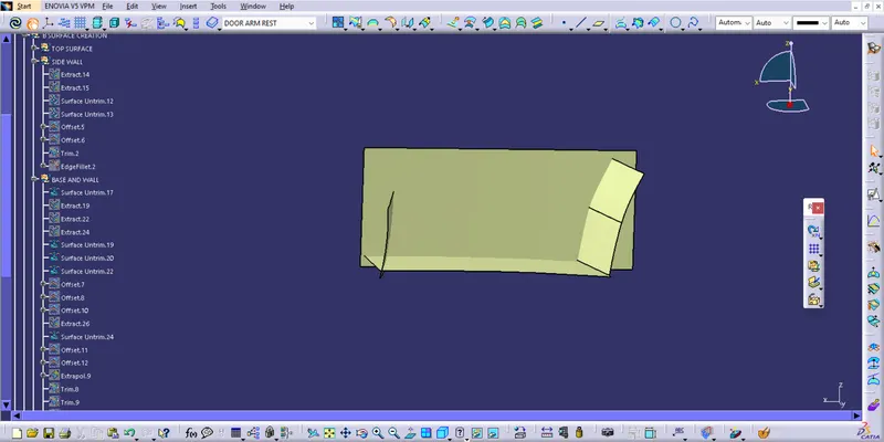
After extraction the surface are untrimed and extrapolated to required amount, offseted . At last the surface are trimmed and formed as single object.
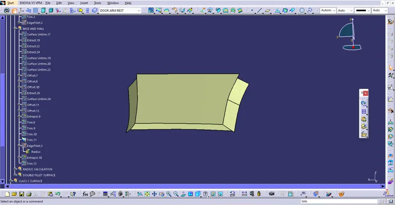
Base and side walls are trimmed
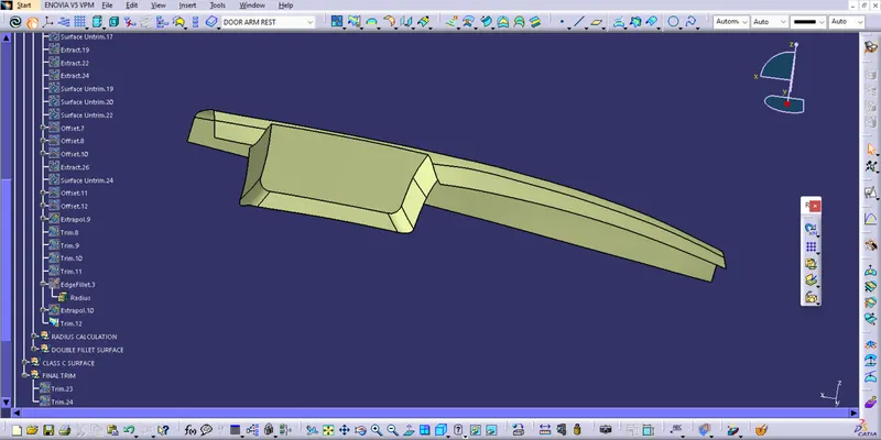
In order for this part, a sketch containing a line tangent to the surface is created, which is swept along.
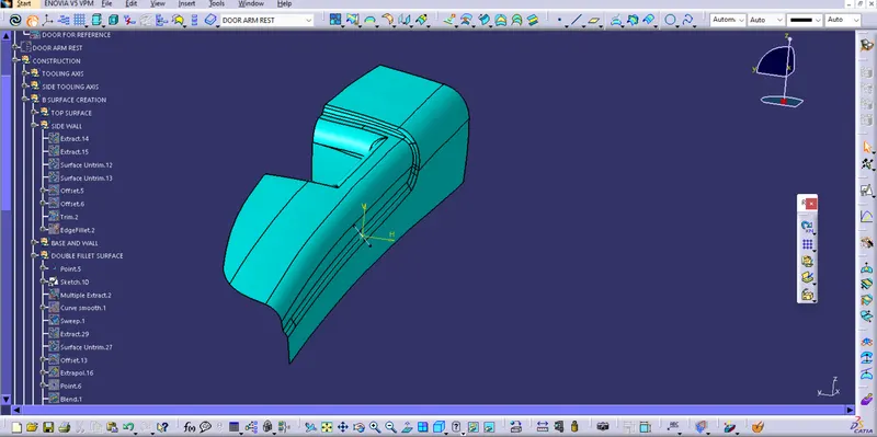
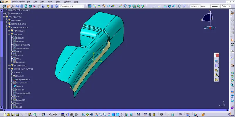
The corresponding rest profiles are extracted and then they are blended together followed by the join command.
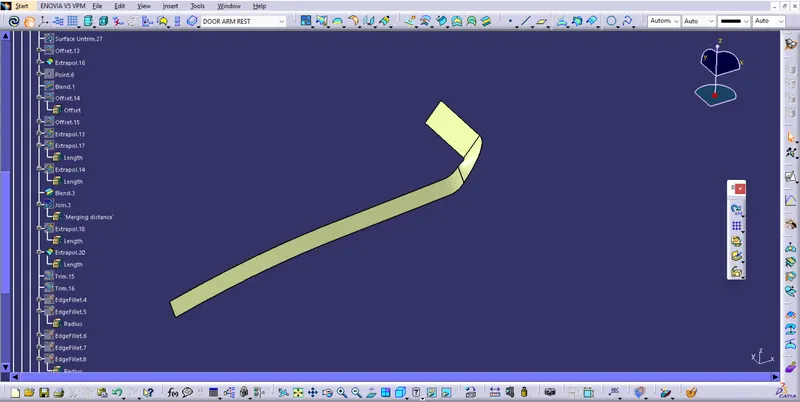
Then this is trimmed with the surface top on the part.
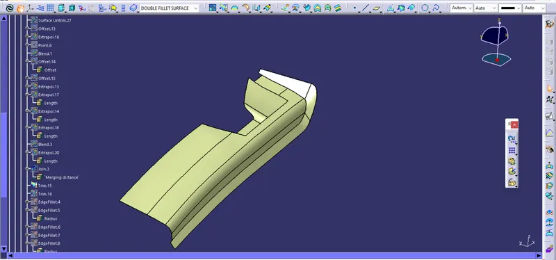
Then with the other half of the created surface these are being trimmed into.
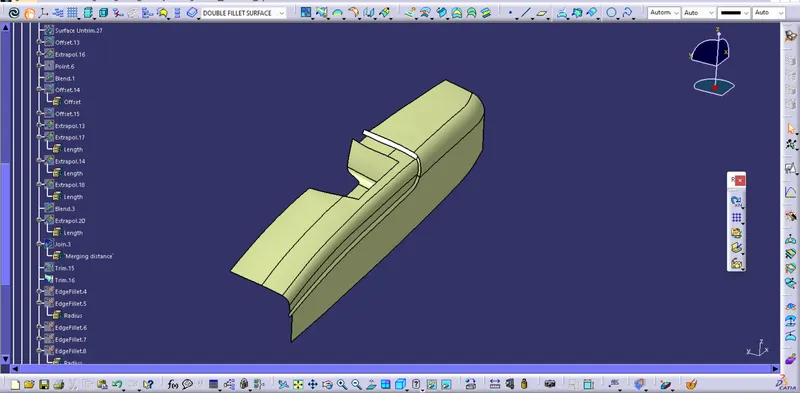
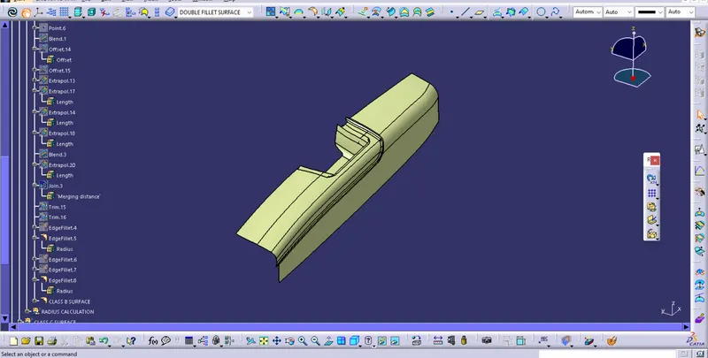
Then all the edge are filleted by respective radius and Class B surface is created.
CREATING CLASS C SURFACE
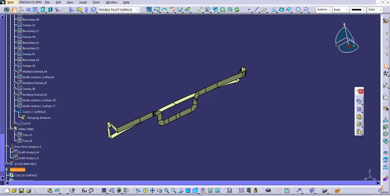
Class C surface is creted by extracting and sweeping the edge of class A surface. Here edges are not in the same shape and direction so CLASS C surface created using boundary, multiple extract , sweep and multi section surface tool. At last all sweep surface are joined . Sweep is formed by considering draft angle as 3.
FINAL TRIM
After creating class c surface . Class A surface and Class C surface are trimmed together.
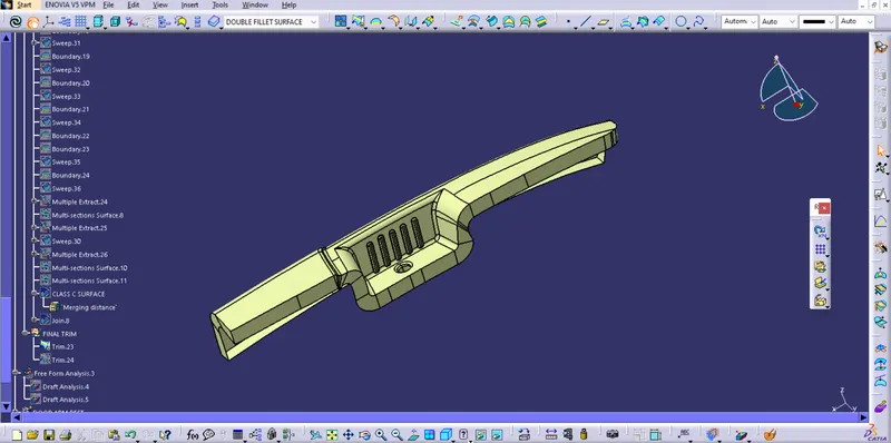
Then trimmed part and the Class B are trimmed . It gives the final output.
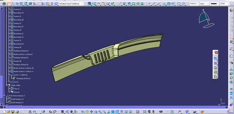
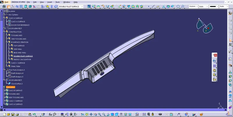
Then the closed body is carried out for the surface making it into a part component for further purpose. Solid body is created using close surface tool.
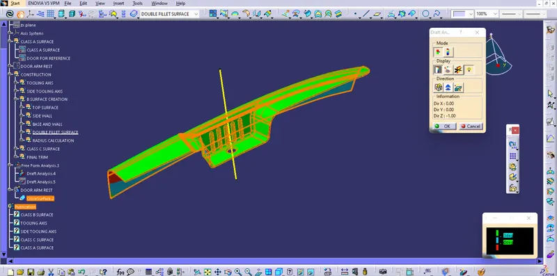
DRAFT ANALYSIS
Analysis report of part body
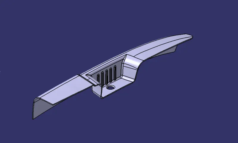
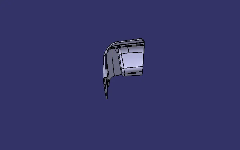
DIFFERENT VIEWS OF PART BODY
ISOMETRIC VIEW
FRONT VIEW
SIDE VIEW
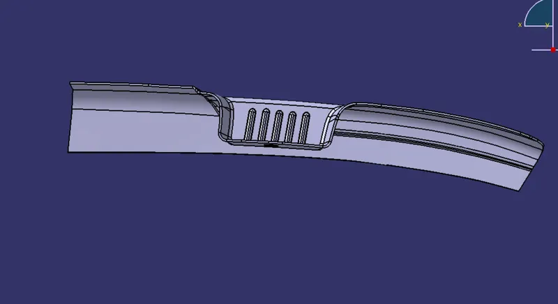
TOP VIEW