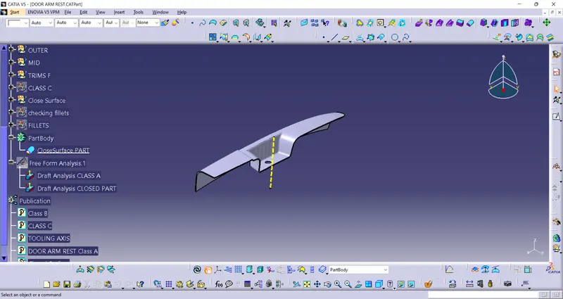
Door Arm Rest Week 8 Challenge
Door Arm Rest
Draft Analysis:
Draft analysis helps to detect if your drafted part is easily removable from the mold (in case of plastic component) or die (in case of sheet metal). All plastic components will have a minimum draft of 0.5 to 3deg. And for automotive sheet metal parts the draft will be 7deg or more. If a mold wall is perpendicular to the part ejection, there is ample friction or interference between the mold and the part which will not allow one to release from the other. This is why design engineers give a minimum draft to the part.
Performing the draft analysis:
- Open Feature draft analysis option from Insert > Analysis > Feature draft analysis.
- A new window pops up by default it will be in quick analysis mode. Change the range to 2.9deg.
- Next you have to position the compass on the tooling axis by dragging the compass from top right corner of the working area. The W axis of the compass should be inline with the axis.
- .Then you have to define the compass by click on compass icon on the draft analysis window. Then lock the positon of the compass by clicking the lock icon.
- After that select the surface and the whole surface will shows a color range. For a good draft make the surface fully green.
DRAFT ANALYSIS FOR CLASS A SURFACE
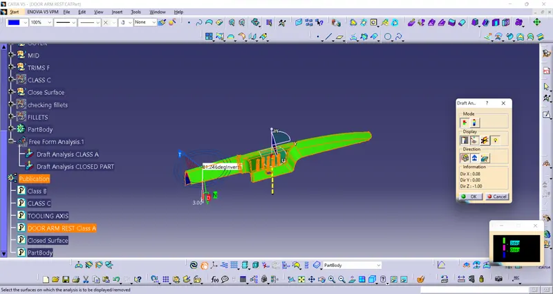
DRAFT ANALYSIS FOR CLOSED PART WITH MAIN TOOLING AXIS
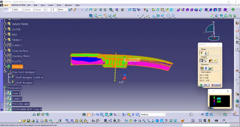
DRAFT ANALYSIS FOR CLOSED PART WITH SIDE-CORE PROFILE
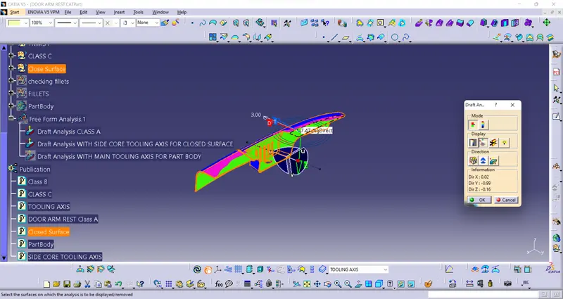
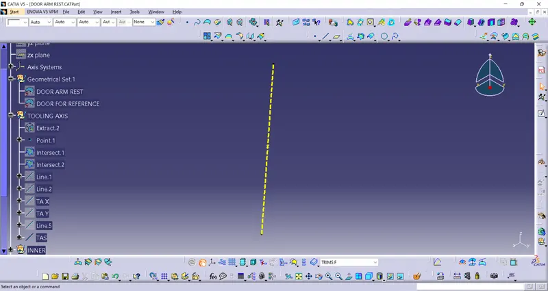
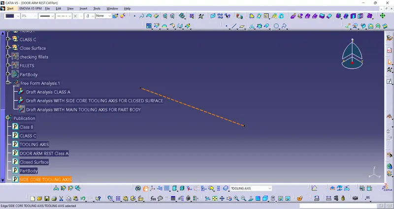
CREATE TOOLING AXIS:
1. Create point on the middle of the hole. And insert the system axis.
2. Create intersection on the XY plane.and draw a line on the two walls and create bisecting line using with two lines
3. And create another intersection on the YZ plane cut half section and creating intersection it has only one wall. Creating one line on the wall inter section and draw a random line on the point this line gives angle from the inter section line.
4. After creates Tooling Axis with using above bisecting and random line. 5. Create another tooling directioon through Y direction.
SIDE-CORE TOOLING AXIS
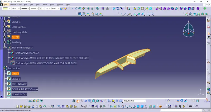
B SURFACE CREATION:
1. Extract the arm rest top surfaces.and un trim and do extropolate up to 50mm. 2. Create a sketch on the middle othe surfaces for getting two curves between the surfaces.create a line through y direction, and exrude a surface using guide curve and create a bend between the one of the top surface and middlle plane.
3. and trim the all surface of the top and offset 2.5 mm
4. And extrude walls and untrim it than extrapolate up to 50mm.and
5. give the edge fillets based on dimensions of the fillets.
trim the surfaces.
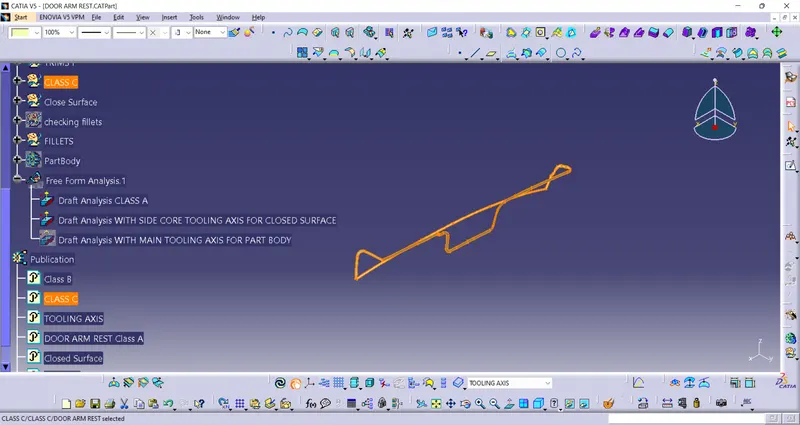
C SURFACE:
• Create a boundaries on class A surface on step by step based on staright plane and curved planes.
- creates boundaries differently divided by the angle of the boudary.
- crerate sweeps on boundaries
- we will get small gap between the surfaces its cleared using with joinig otption gap value is mantain 0.3.
- trim the sirfaces and join the classA And class b surfaces.than will get c curface.
- Than will go to part design and fill the surface.
CLOSED SURFACE
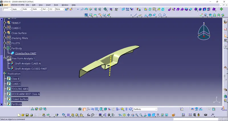
CLOSED PARTBODY