Door Arm Rest Week 8 Challenge
Tooling axis
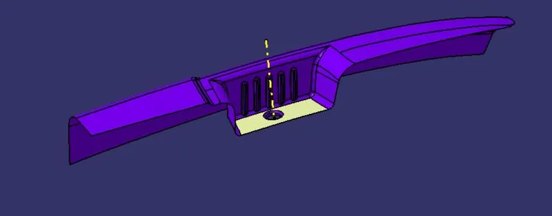
The tooling axis created using the surface of the base. The line is created with the point and directed along normal to the surface.
Draft analysis:
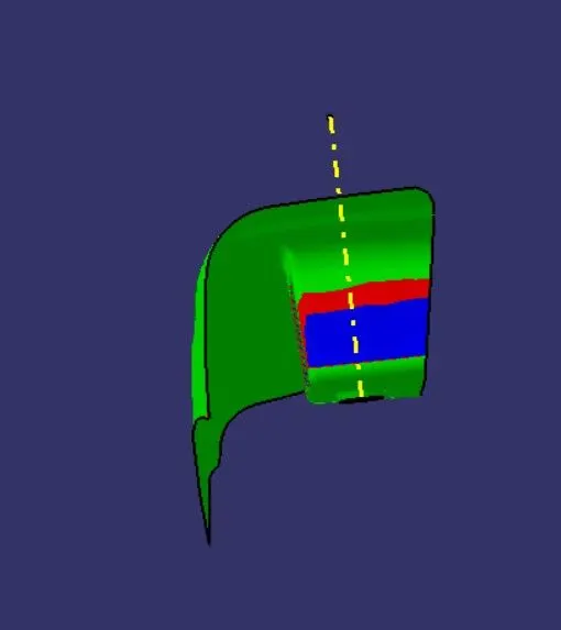
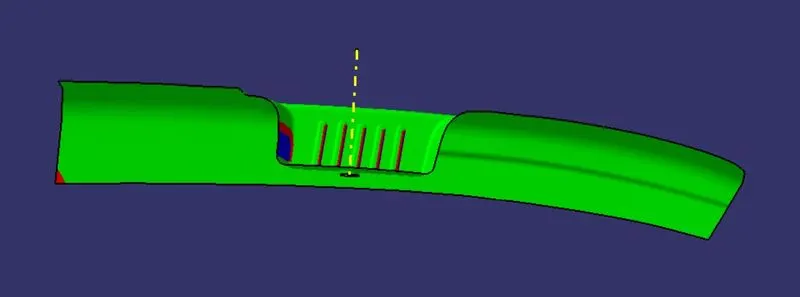
The Draft Analysis command enables you to detect if the part you drafted will be easily removed. This type of analysis is performed based on color ranges identifying zones on the analyzed element where the deviation from the draft direction at any point, corresponds to specified values.
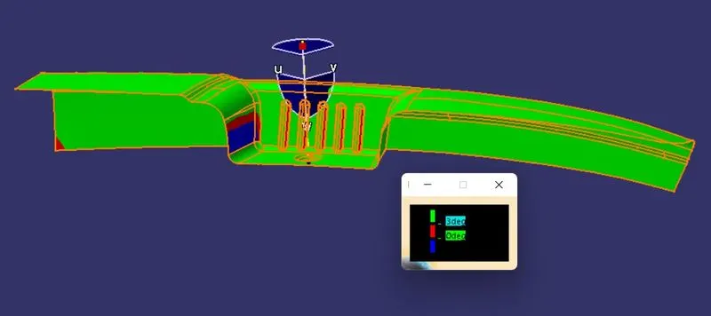
We can see some of the surfaces were below 0 degree to the tooling axis. There is nothing we can do in this case. We need to inform to the class A surface creation team to change the surface as per our requirment.
Class B creation.
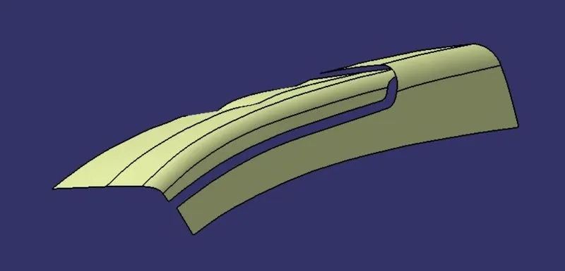
To create the class B surface first the base elements were extracted and then the surfaces were untrimmed then extrapolated to some distance.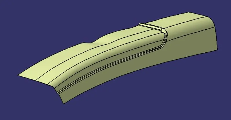
To join the previous to surfaces the above surface created then trimmed with the base surface.
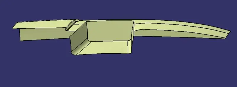
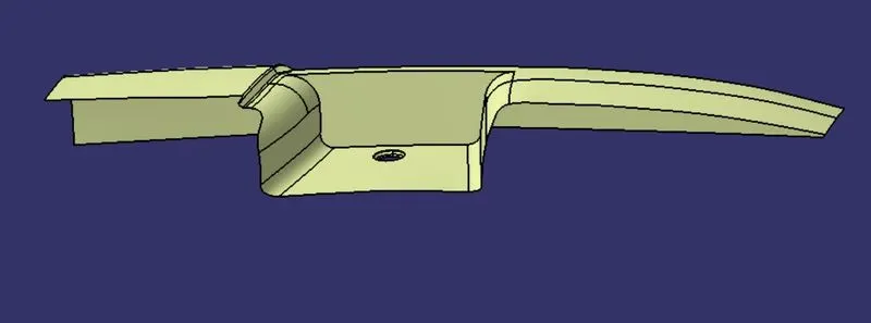
Then the pocket surfaces were extracted and then the surfaces were untrimmed then extrapolated to some distance.
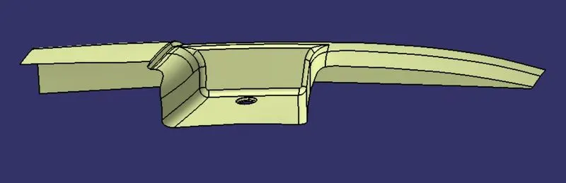
The fillet was applied to the required edges.
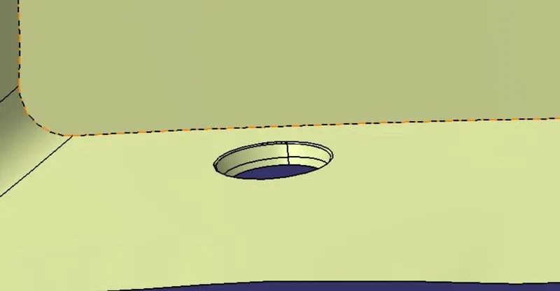
The hole faces also extacted and then the surfaces were untrimmed then extrapolated to some distance.
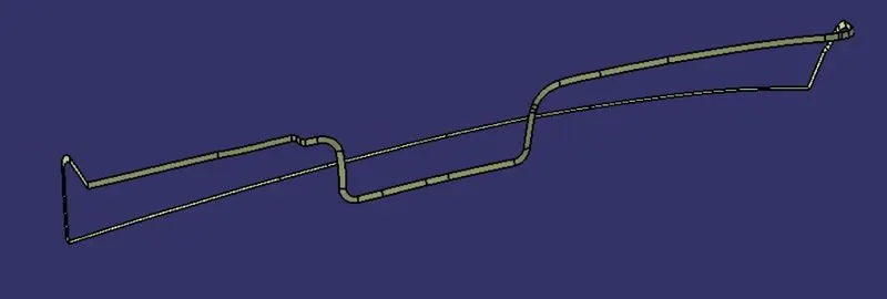
The class C surface was created seperatly for the each element with the angle of 87 degree.
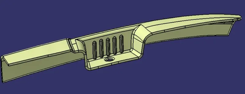
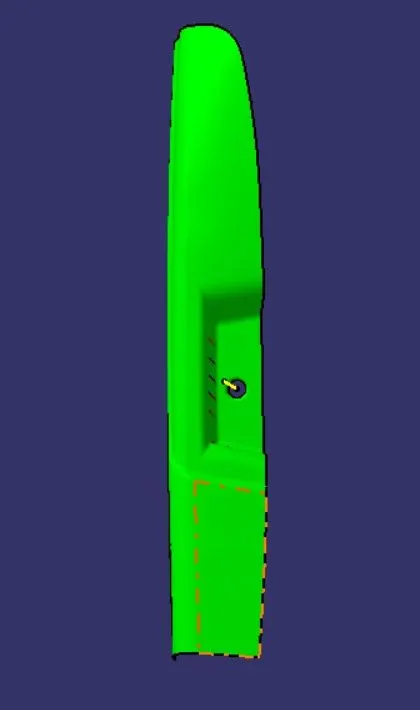
then the class A and class C surfaces were trimmed together to get the above result.
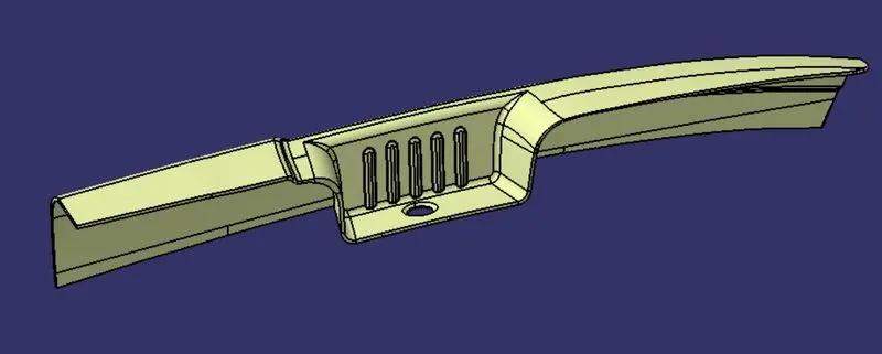
Then the trimmed surface again trimmed with the class B surface.
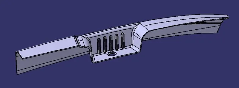
After all this the closed surface command used to create the soild out from the surface.
Views for draft analysis
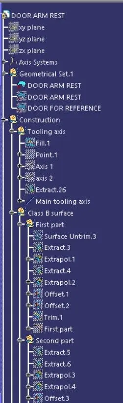
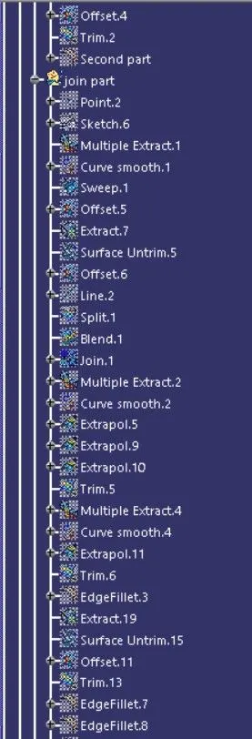
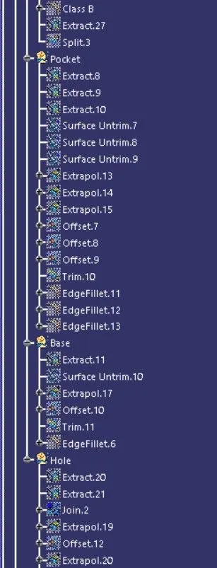
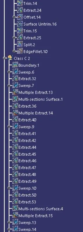
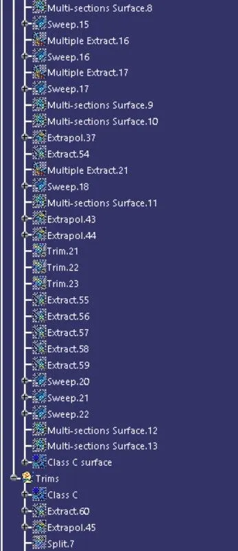
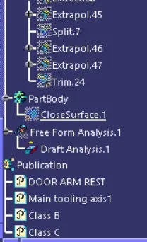
Tree stucture