Door Arm Rest Week 8 Challenge
ANSWER:
DOOR ARMREST DESIGN:
The main objective is to create a tooling axis for a given Door Arm Rest by satisfying the construction of surfaces and to perform draft analysis to check if the part has given a draft to the surfaces which are lying parallel to the tooling axis. Also, to create CLASS B and CLASS C surfaces from the given CLASS A surface of the door armrest to create the solid part with proper draft standards.
DRAFT :
In engineering, the draft is the amount of taper given to the surface of molded or cast parts perpendicular to the parting
line. The in-build draft analysis tool used in CATIA to ensure that the faces are taper with the respect to the tooling axis. The tooling axis is the direction of mold part ejection. The draft is provided on both core and cavity sides of the parts, which are produced using molding, to reduce damage to the surfaces during ejection. Usually, the draft angle should be 3 degrees.
CREATION OF TOOLING AXIS:
STEP 1 - Create a dummy tooling axis
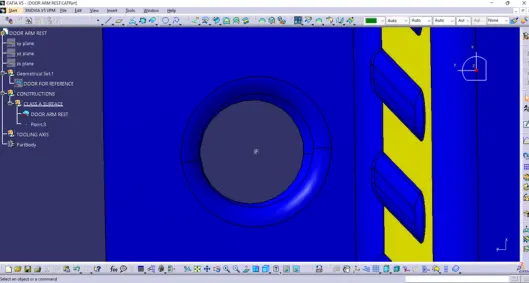
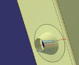
When trying to create a point in the center of the sphere, it was generating more than one point as shown in the below figure
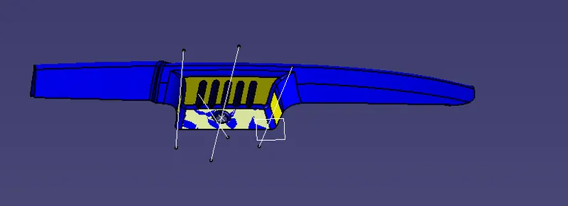
Create a three-point rectangle in reference to the extracted surface and create a point at its center
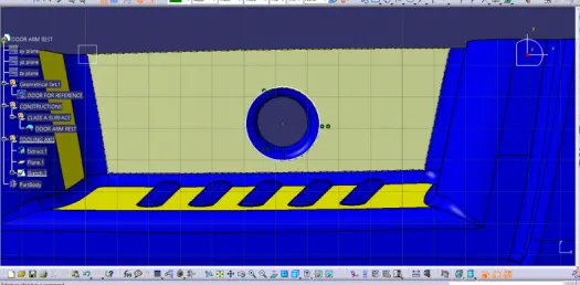
Dummy tooling axis
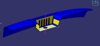
STEP 2 - Create a tooling axis for x-direction
Create an axis system at the reference point. Open a positioned sketch and intersect the XZ plane with the surface.
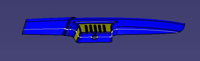
Extend the taper edges of the profile using line and create a bisecting line
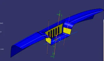
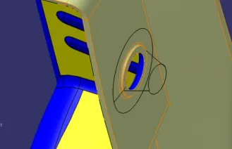
Similarly, do the same for the taper on the hole
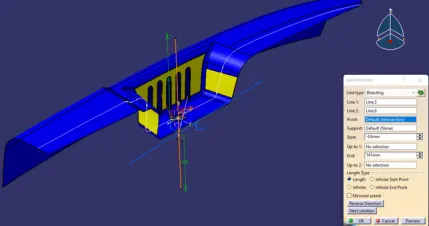
Create the bisecting line for both x-direction dummy lines, and that one is the tooling axis for the x-direction
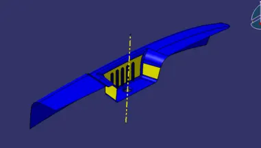
STEP 3 - Create a tooling axis for Y-direction
Create a line using the positioned sketch and with reference to the surface as shown in the picture below
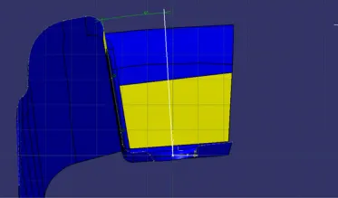
Also, create extending lines for the taper on holes and create a bisecting line
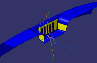
Now bisect both dummy axis of the y-direction
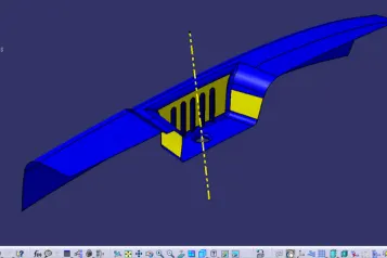
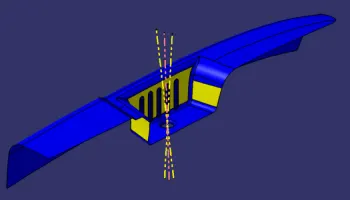
STEP 4 - Creating the final tooling axis
Bisect both the x and y direction tooling axis to create the final tooling axis
DRAFT ANALYSIS:
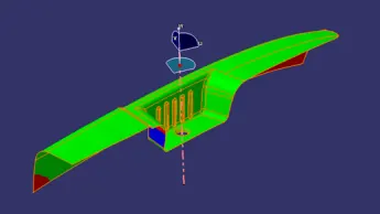
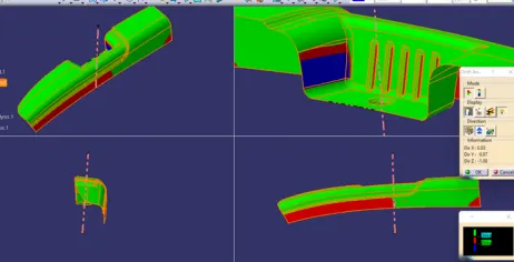
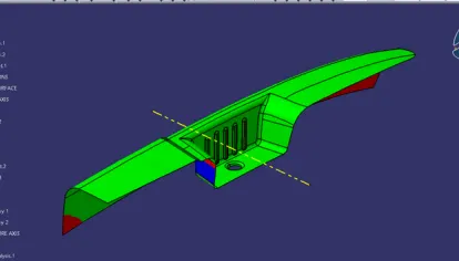
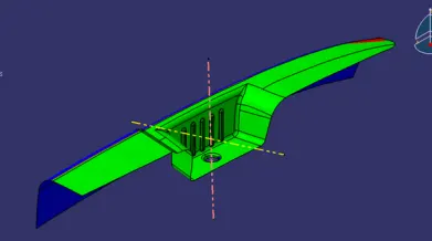
If we observe from the above picture, it is observed that some portions of the surface do not meet the standard
drafting criteria.
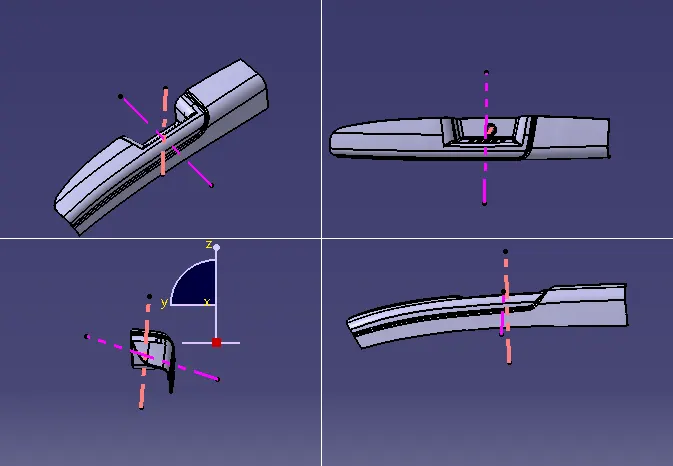
This type of surface requires a SIDE CORE. To create the side core axis.
SIDE CORE:
Create the side core axis in the Y direction
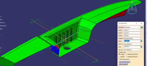
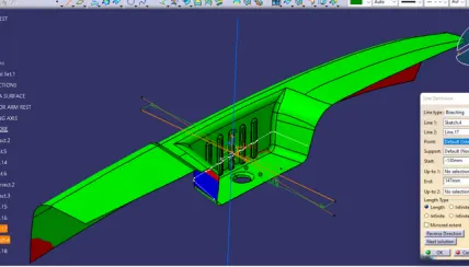
CLASS B SURFACE
Take the point on the edge and insert an axis system. Now create a line on that edge as shown in the below picture
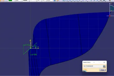
Extract the edge as shown in the picture and smooth the curve
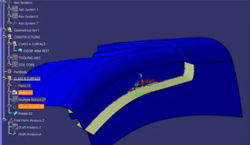
Extract the edge, un trim it, and extrapolate on three edges
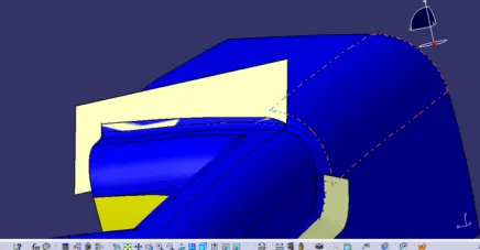
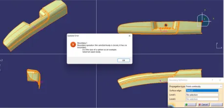
Combine both the ends of the surface using a multisection surface. The guide used is extracted using multiple extracts and
that that curve is smoothed using a smooth curve.
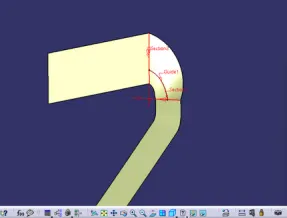
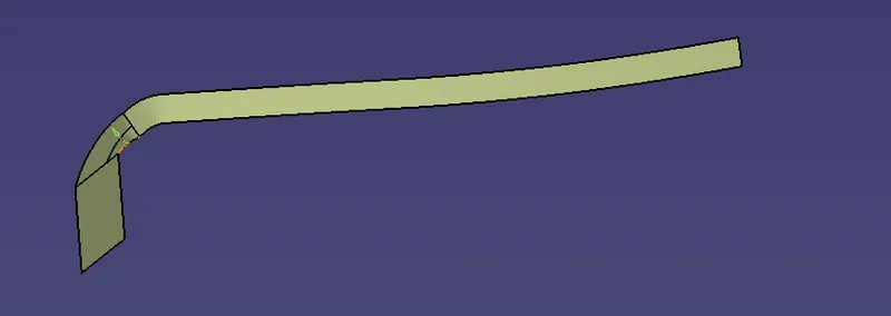
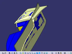
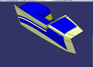
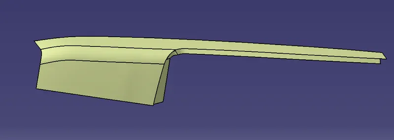
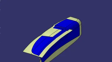
Do the same for another set of surfaces
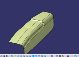
Now trim the unwanted surface
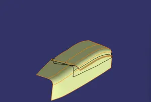
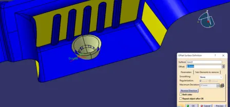
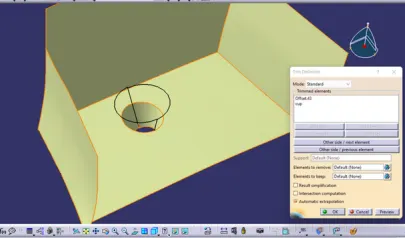
To create the cup-shaped surface, follow the process, extract the surface, un trim it, extrapolate the surface and offset
the surface to 2.5 mm. Finally, trim the unwanted surfaces. The output after doing these is as shown in picture
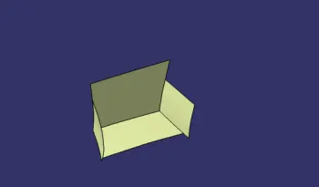
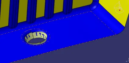
Extrapolate the edge
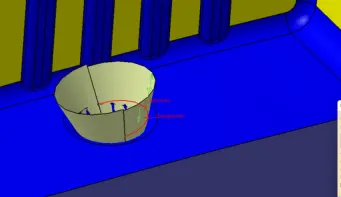
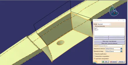
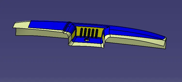
All the required surfaces are created, Now apply the fillets. To find the fillet radius, use intersection curves
The final CLASS B surface
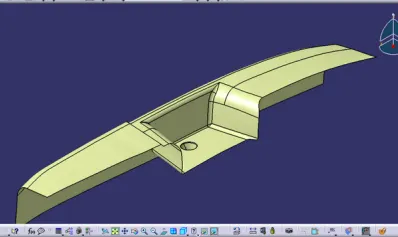
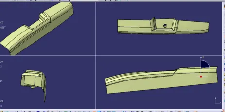
CLASS C SURFACE:
Using the multiple extract feature, extract the edges of the given class A surface as shown
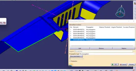
Smooth the curve and swept with the draft direction
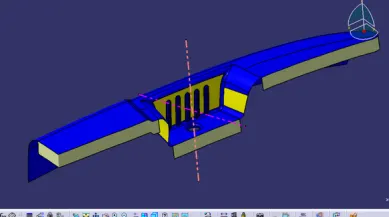
Join the open ends of the swept surfaces using multisection surface
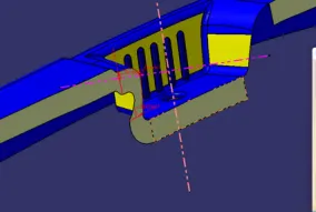
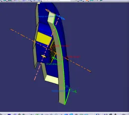
Join both the class C edges with multisection surface
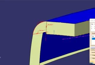
Also, do the same on the other side
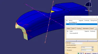
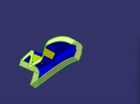
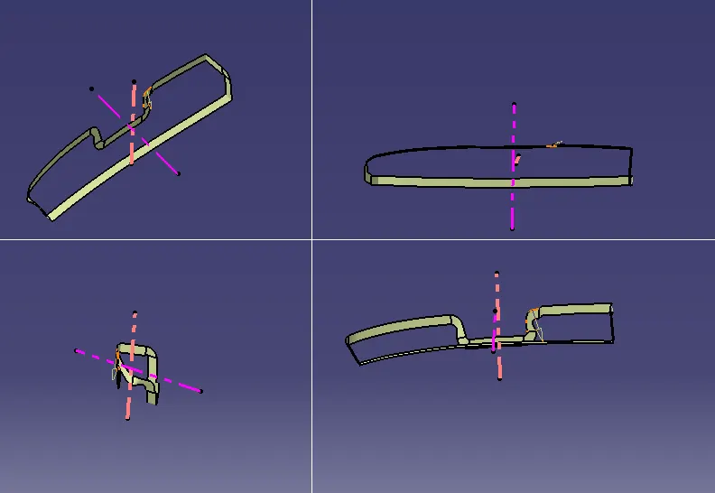
SOLID PLASTIC PART:
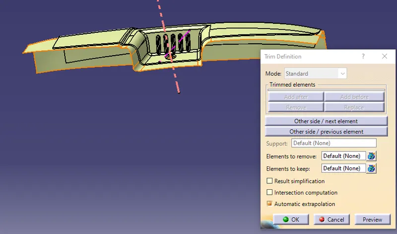
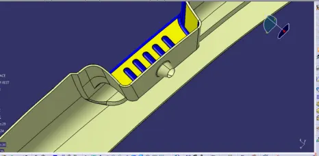
Trim the unwanted edges
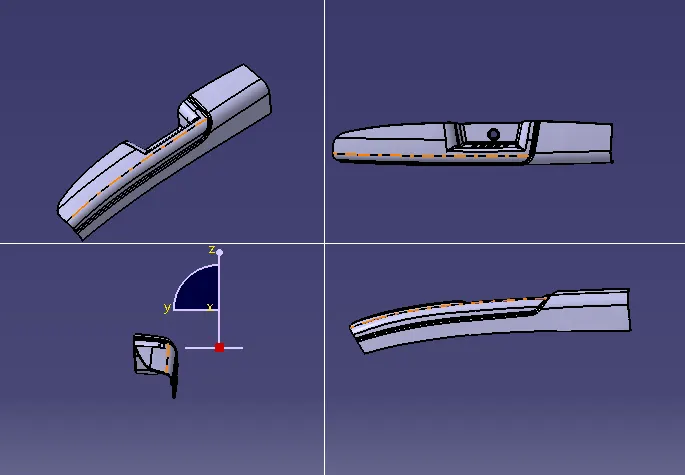
DRAFT ANALYSIS ON PLASTIC PART:
Draft analysis using tooling axis
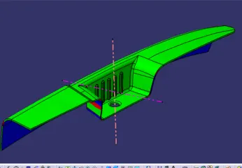
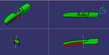
Draft analysis using side core axis
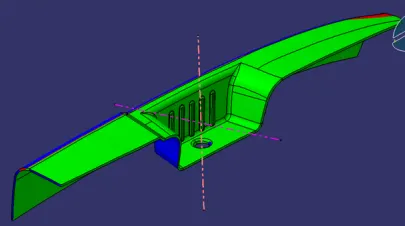
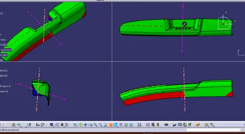
From this analysis, it is concluded that the surfaces which do not satisfy the tooling axis draft analysis are solved
using the side core axis draft analysis.
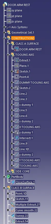
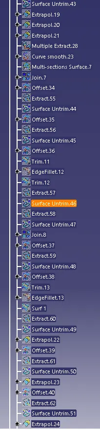
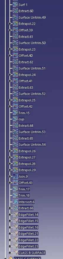
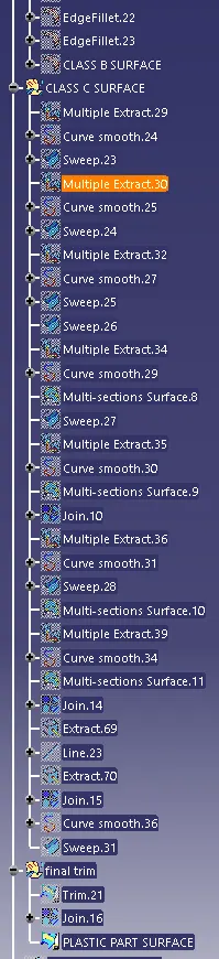
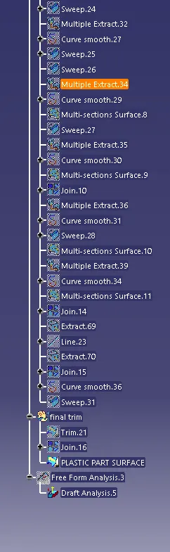
TREE STRUCTURE:
Conclusion :
The draft analysis is done on the given class A surface of the Door Arm Rest, and it is found that the surfaces are having the minimum draft, and it is suitable for manufacturing. The class B and class C surfaces are created, and a solid part is created from all surfaces.