Door Arm Rest Week 8 Challenge
DOOR ARM REST
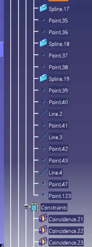
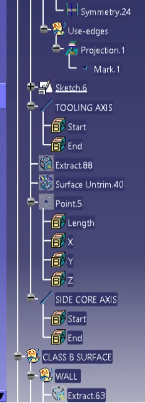
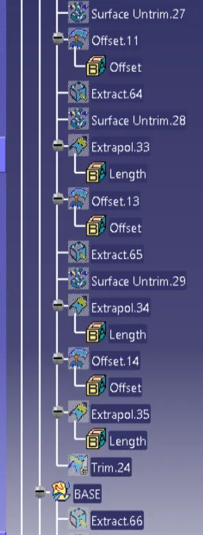
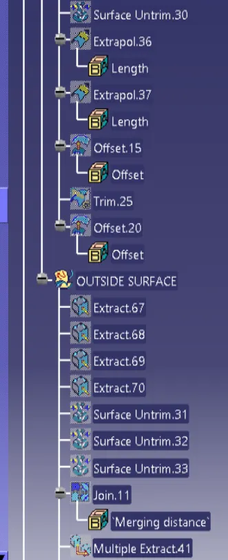
1. Tree Structure and Geometrical Sets
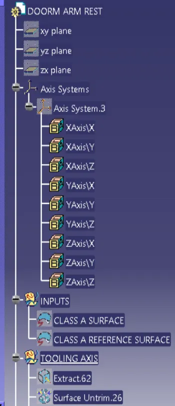
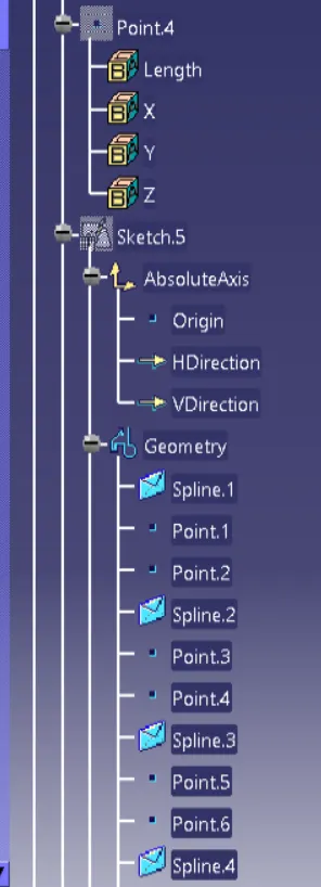
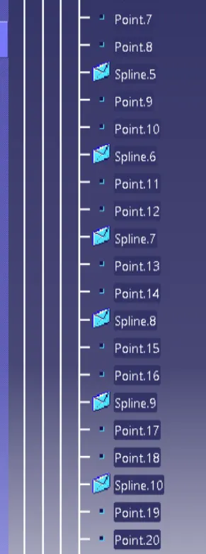
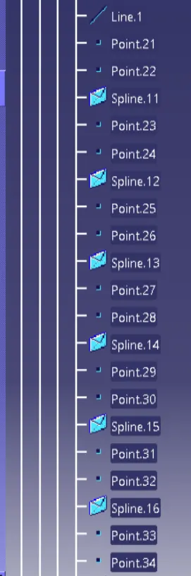
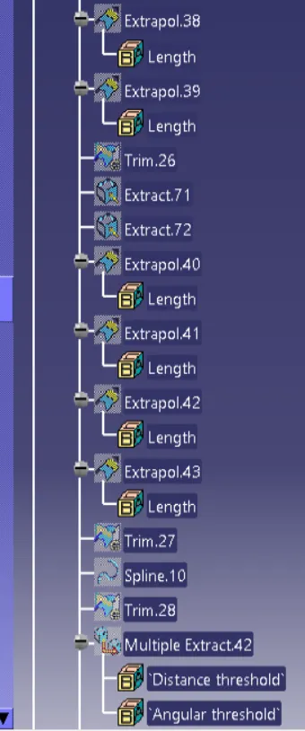
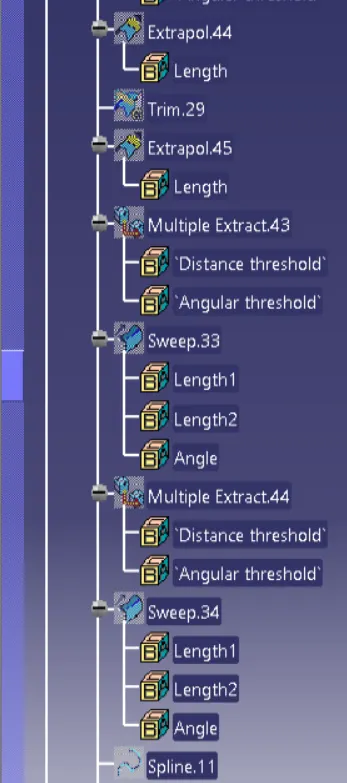
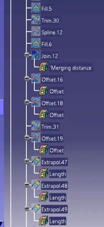
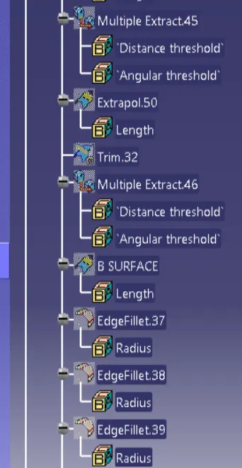
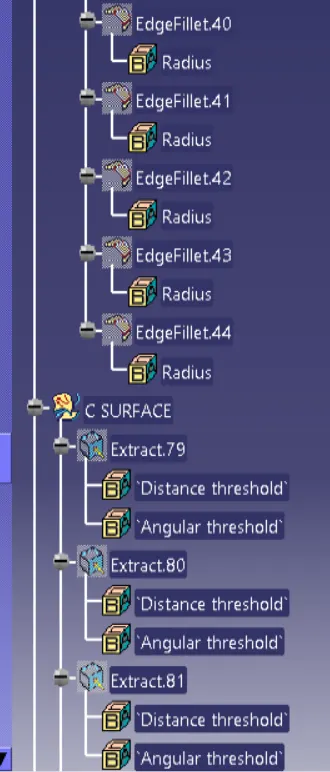
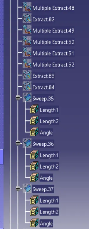
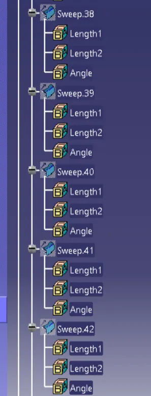
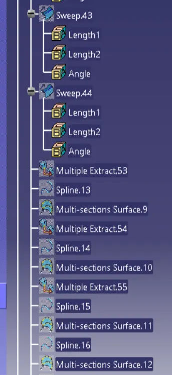
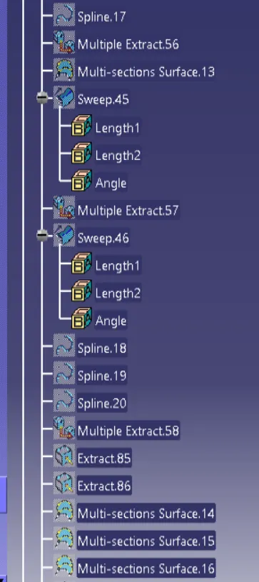
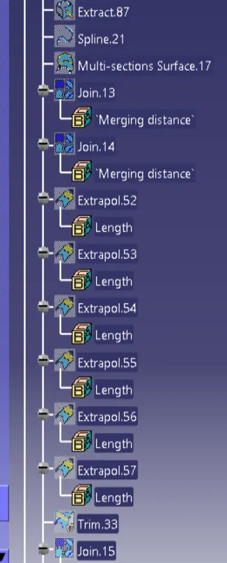
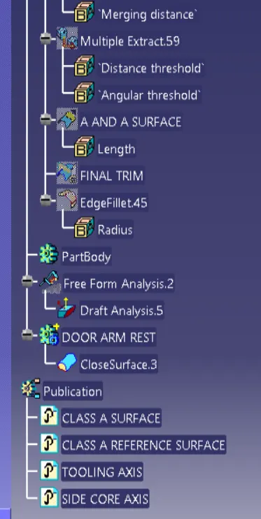
2. The Various Oreintation View of Door Arm Rest
- Front View
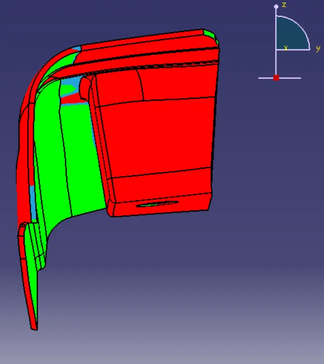
- Side View
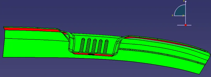
- Top View
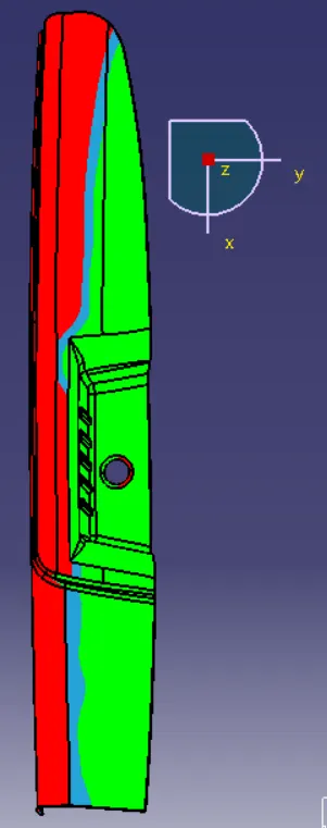
- Isometeric View
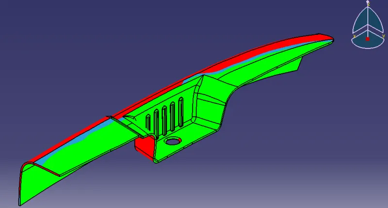
3. Tooling Axis
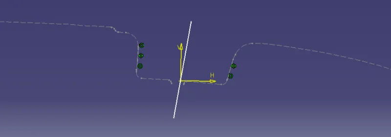
Extract the base surface from the class A surface and create the point on the center for the first bisecting line
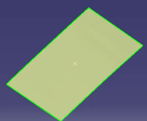
First Sketch
Second Sketch
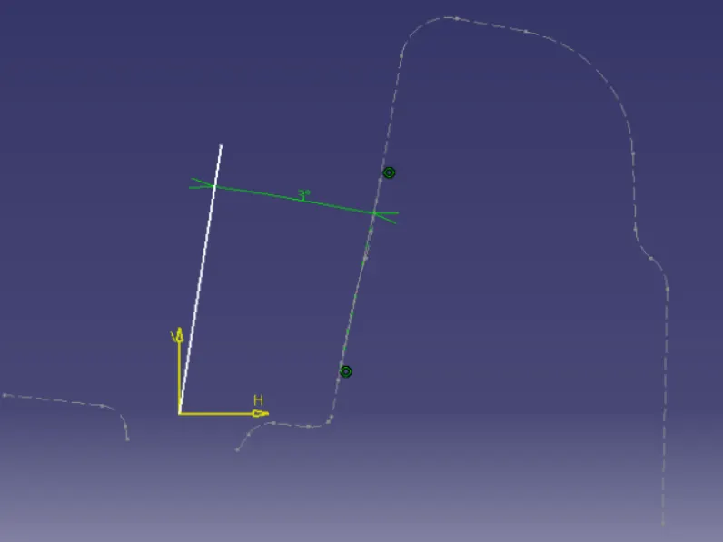
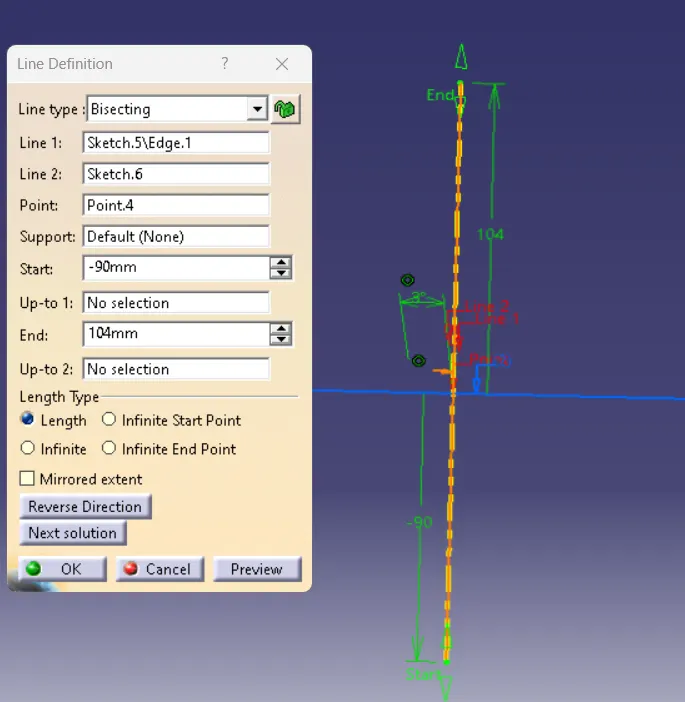
Bisect the first and second you will get Main Tooling Axis
Side Core Tooling Axis
Extract the wall surface from the class A and untrim it make a point in center
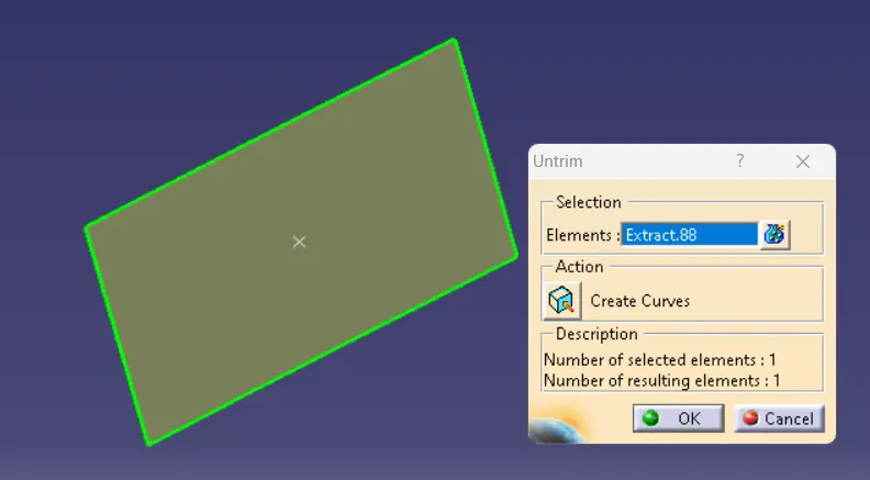
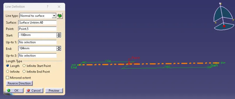
Now Create a Tooling axis on that point, Line type is Normal to Surface
4.Draft Analysis for the Door Arm Rest :
Draft Analysis using the main tooling axis
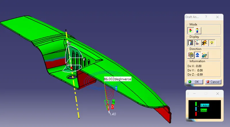
Here the angle value is 0.7 degree it would clear in the side core tooling axis
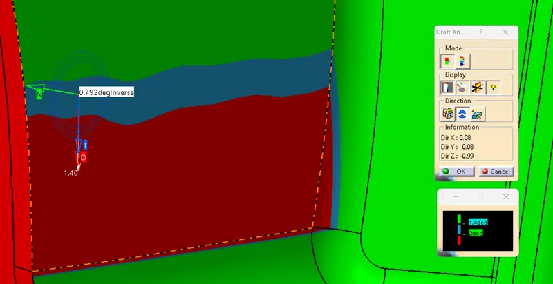
Here the draft angle is -3 degree
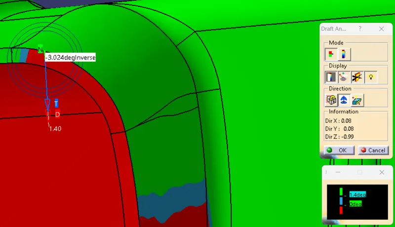
The Positive side of the flip direction for the Main tooling Axis the draft value is 1.4mm draft, the draft value is 0.5mm
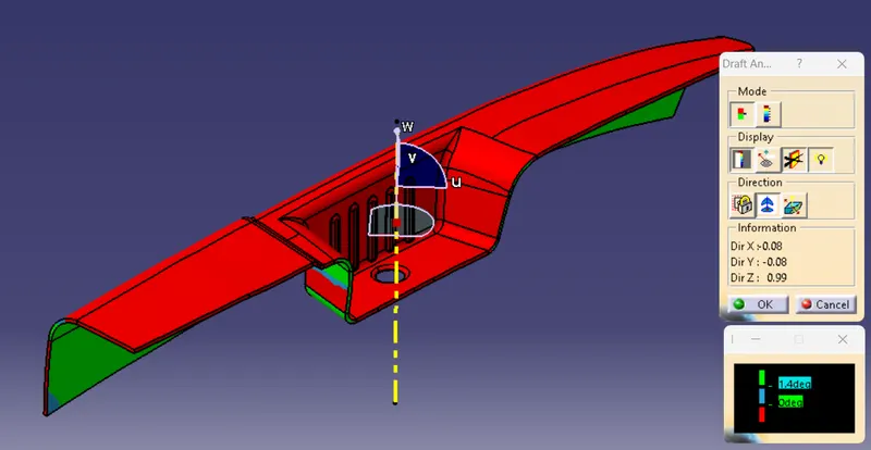
Here the Minimum draft is 0.8mm.
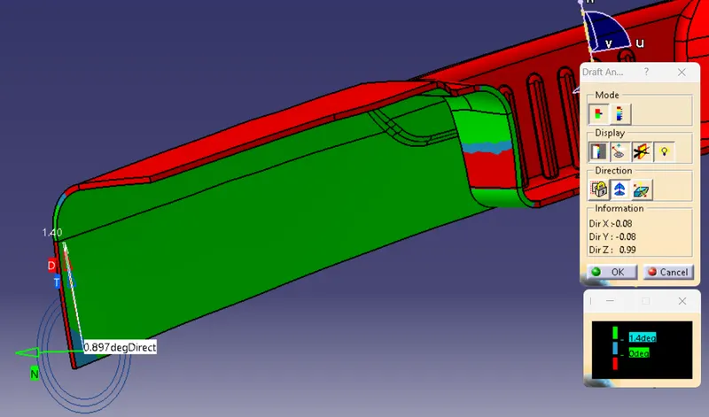
5.Draft Analysis using the Side Core Tooling Axis
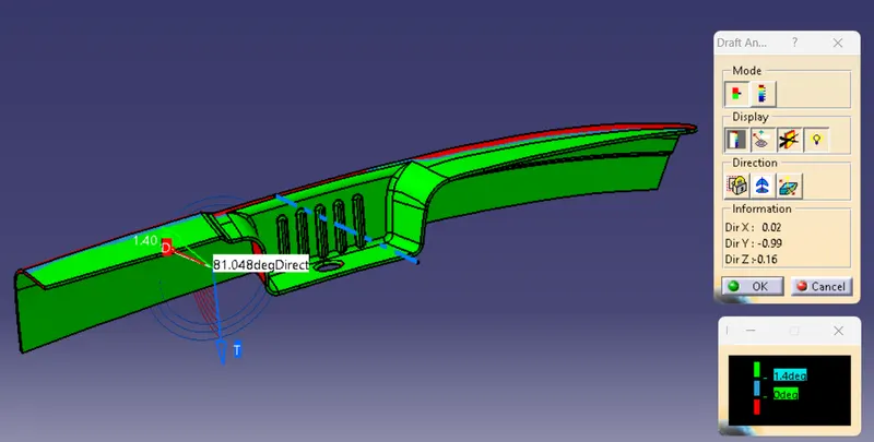
The side which are not clear in the Main tooling it will cleared in the side core tooling axis
1.2 degree at the Blue zone
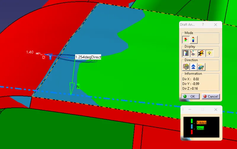
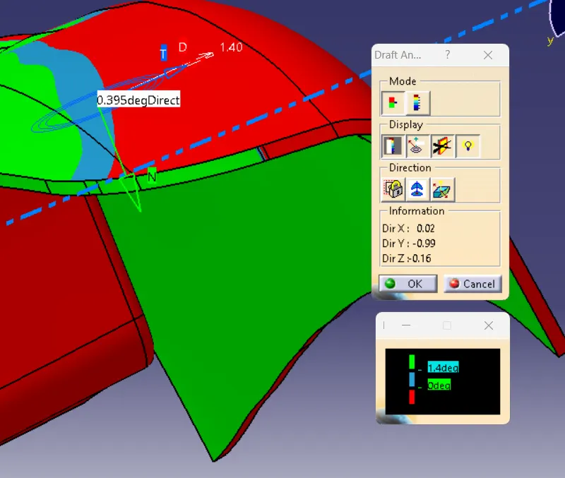
The other Flip side Draft Analysis for the Door Arm Rest
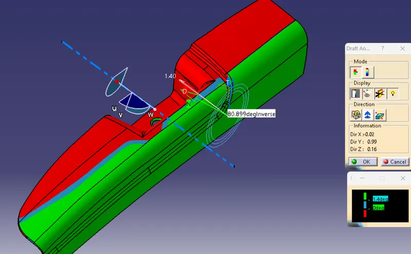
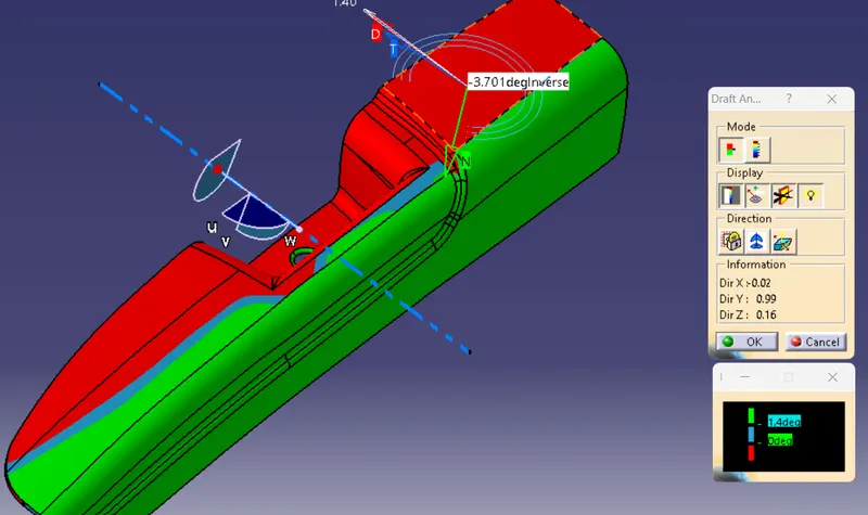
6. Class B Surface and Class C Surface :
Class B Surface
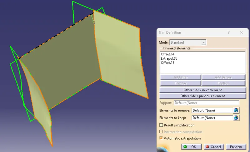
- Wall
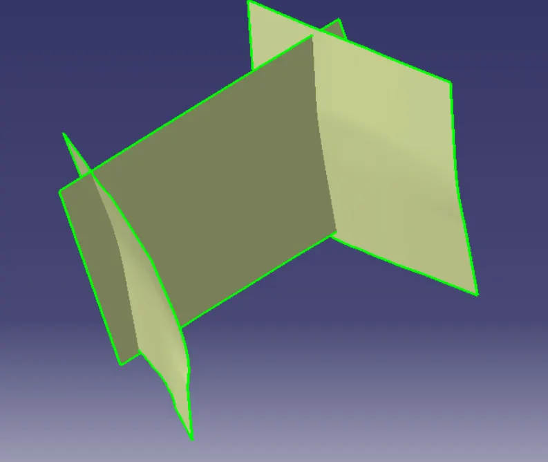
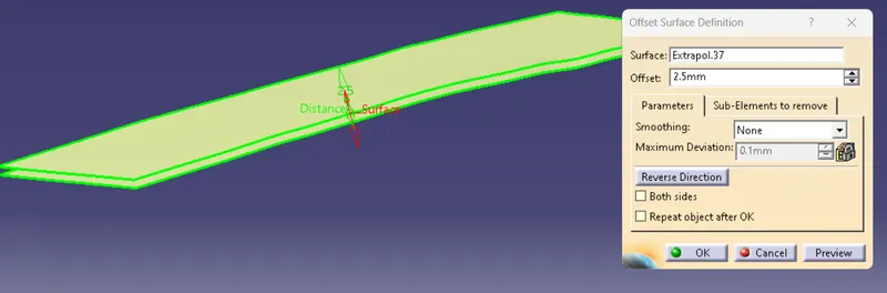
After Exract we have offset the surface at 2.5mm
- Base
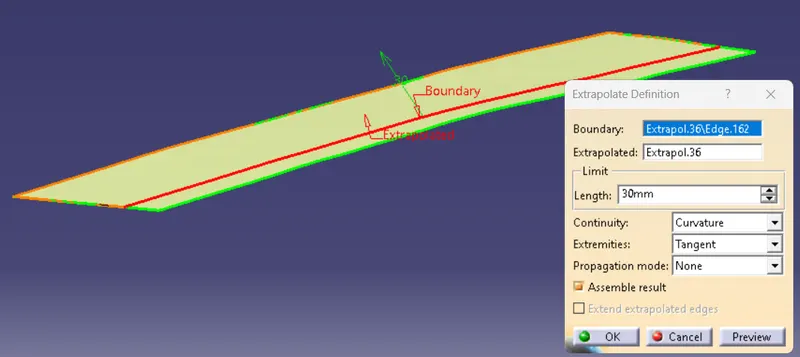
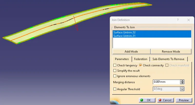
Extract the base from the Class A and offset it then trim with the wall
- Door arm rest
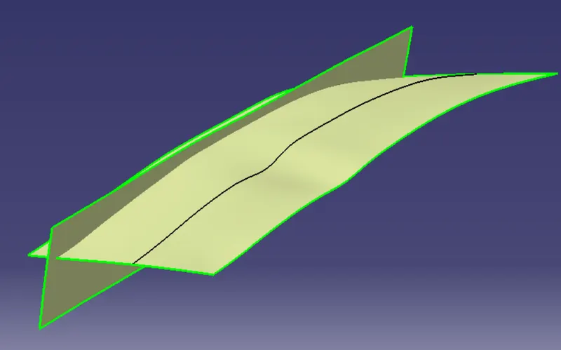
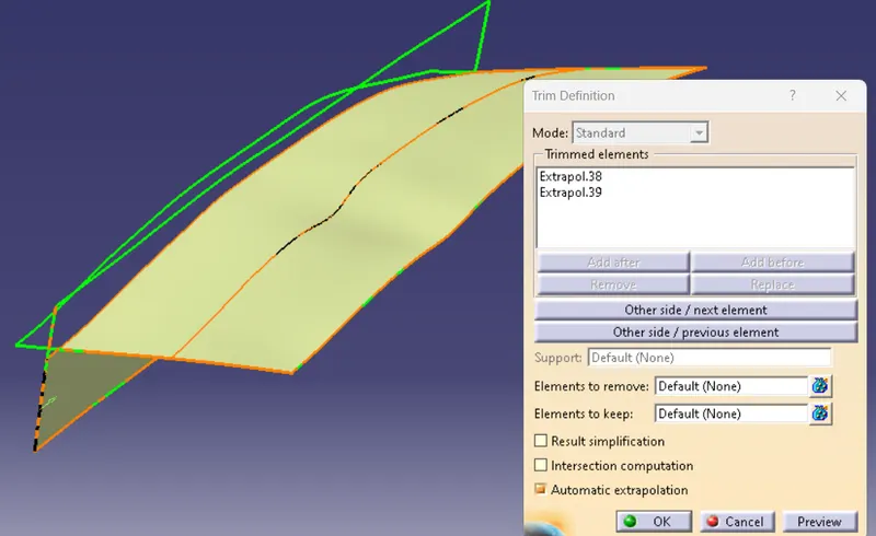
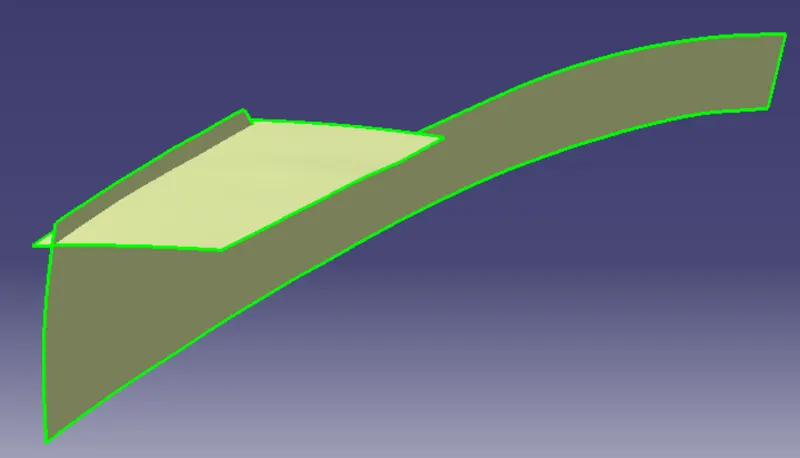
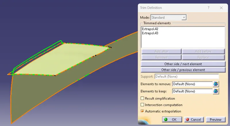
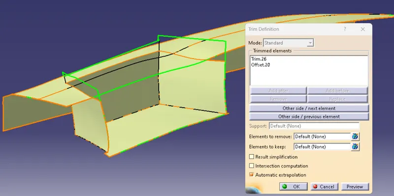
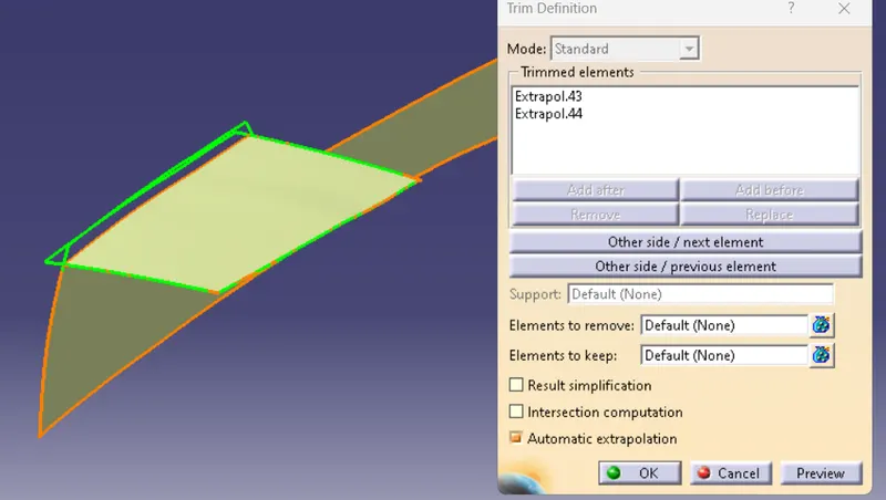
Create the Mutiple Curve and use Swept command for the side cutout
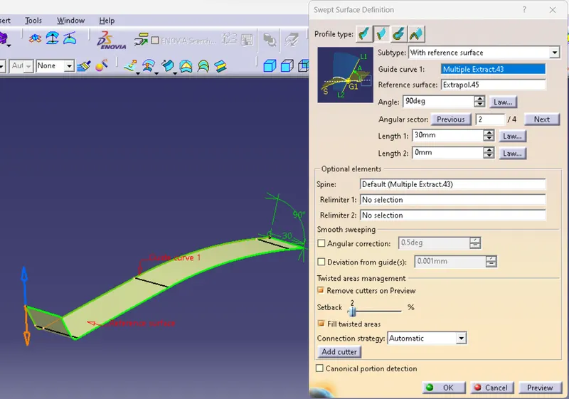
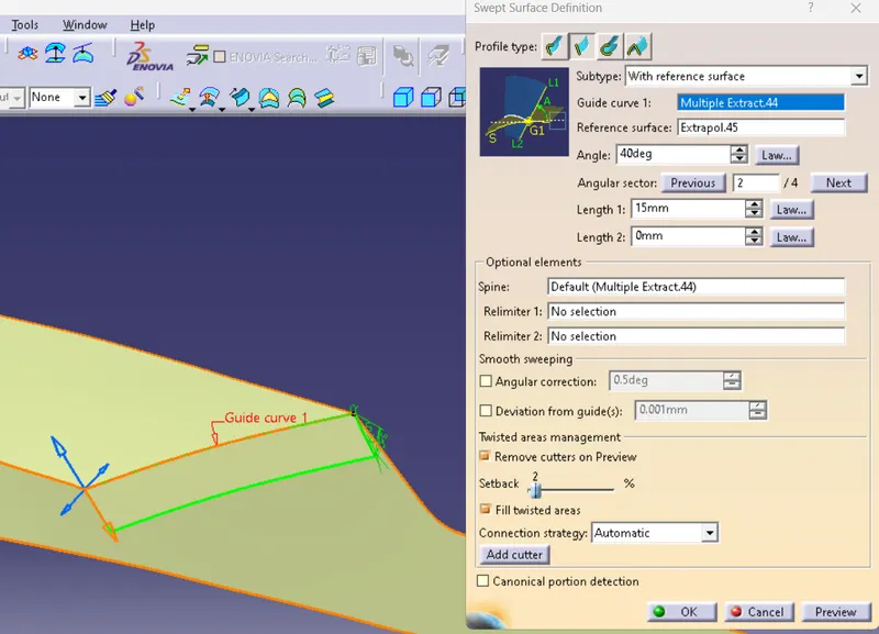
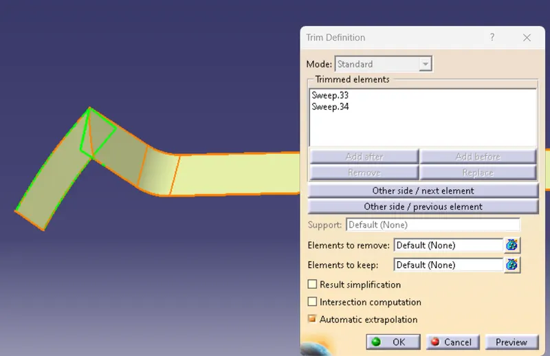
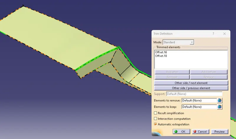
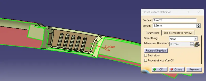
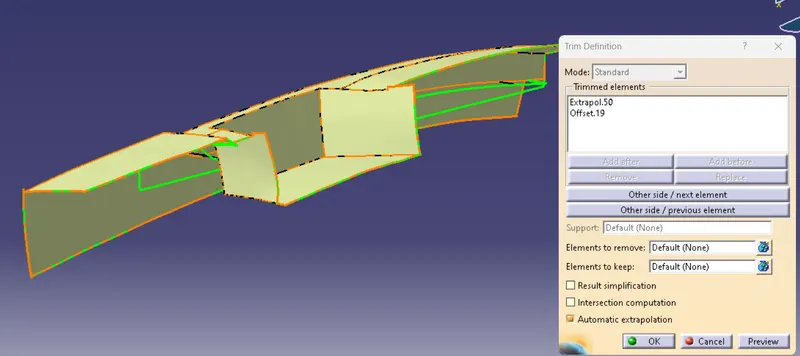
Final Class B Surface , the Fillet value will note in the Class Surface with help of the measuring tool
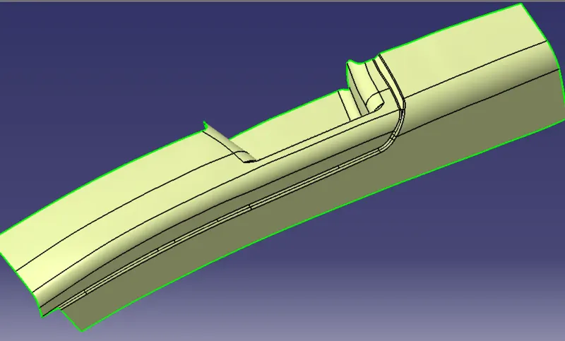
Class C Surface of the Door Arm Rest
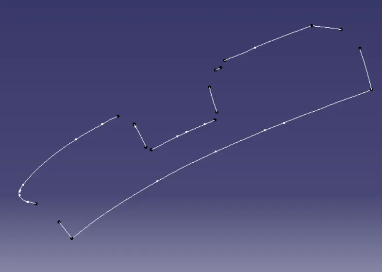
Create an Multiple Extract on the boundary and using Swept it with required Direction
Swept Surfaces
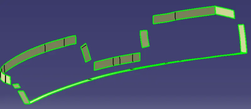
Where the Cap will occur create the Multisection on it
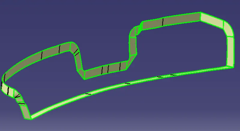
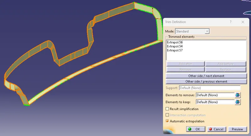
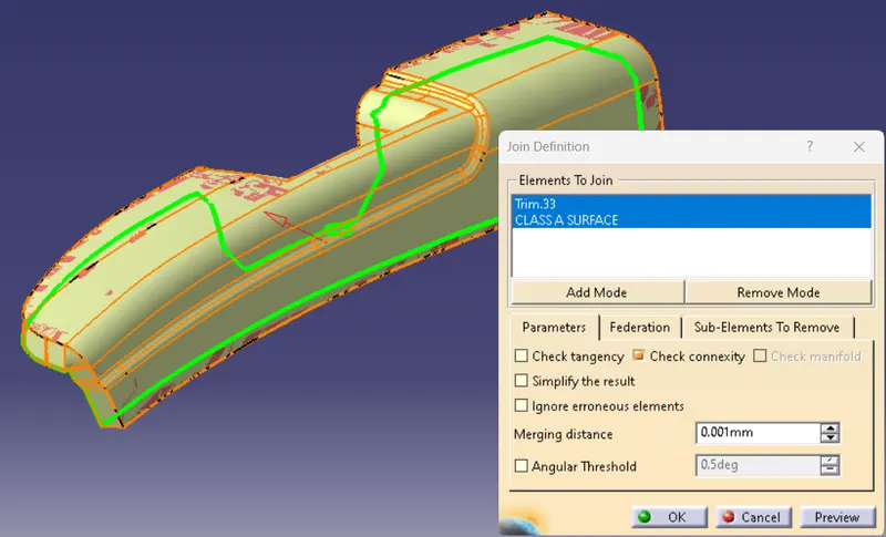
Join the Class C Surface with the Class A surface
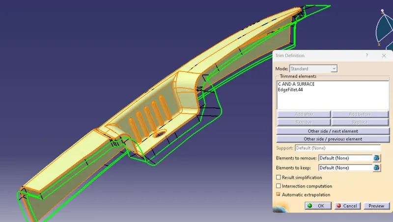
Final trim with the Class B and Class C Surface
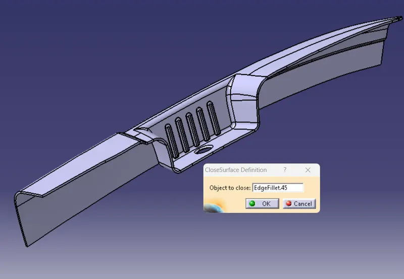
Now the Surface is ready to Convert an solid Close body.
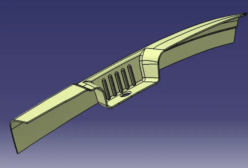
Close surface Body
The Thickness of the Solid Close Body is 2.5mm
Detailed Report for the Door Arm Rest
Tooloing Axis
- The Main Tooling is based for which direction the draft going to be.first we would have create the X axis direction line
and Y axis direction line the bisect the both line and create the main tooling axis.
- Then create the another tooling axis for the door arm because which area are not clear in the main tooling axis it
would clear in the Side core tooling axis. for that select the wall surface and extract it and create the center point on it
then make line using that point.
Class B and Class C Surface
- Class B surface will create with the reference of the class A surface extract all the wall ,base and top surface ,Extrapolate the surface then
trim with the required surface then create the Class B surface.
- For the Class C surface use the multiple extract then extract the outer boundary and use the swept surface command sweep all the curve
and use the multisection for the cap , then join the Class C surface with the Class A surface after the Creation of the both surface
trim them and create the final surface check wheather any cap occur on it.
Then turn the final surface into the closesurface body the Thickness of the Solid Surface is 2.5mm.
Draft Analysis
Insert - Analysis - Feature draft analysis
Create the draft analysis using Tooling axis , the Minimum draft value in 0.5mm
Main Tooling Axis
Side Core Tooling Axis.