Door Arm Rest Week 8 Challenge
AIM:
To create a door arm rest model from given class A surface.
OBJECTIVE:
The door arm rest solid model with design features involved and creation of surface thickness necessary.and draft analysis to be done.
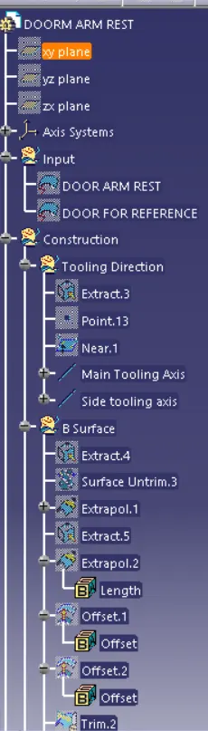
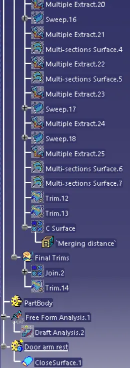
- Ensure proper tree structure
- All sketches should be created under geometrical set
- Closed surface feature should be used to make solid body from surface.
PROCEDURE:
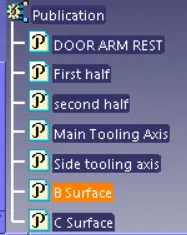
Tooling axis
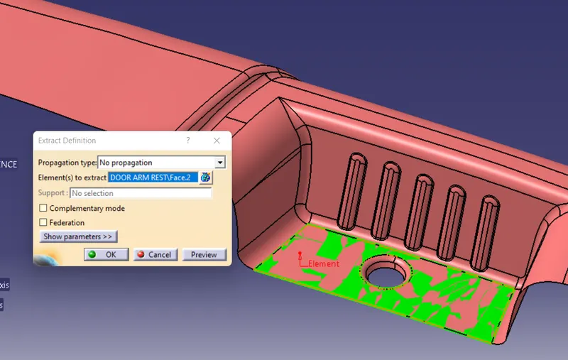
To create tooling direction here we extract a surface and and create a point on extract and now we can make line with point direction option selection along Z axis thus the created line is our main tooling axis
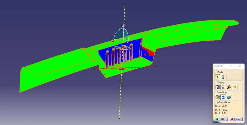
As we can observe all faces are not clearing this is termed as under cut and there are some A side features also we create a side core tooling axis
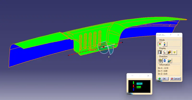
For this we will use new method by making line anywhere in the work bench then we will open draft analysis perform it on the line , then by manipolating the compass to make everything clear in the direction then we will need to lock the compass so that it doesnot move from its place then we will be editing line and provide direction with respect to compass thus side core tooling direction is created.
CLASS B SURFACE CREATION
A class B surface is a surface which is not seen but accomdates the fits and fixtures on it in other words its is opposite side of class A surface and we will have all the supporting features like ribs, bosses, dog house on B surface only
Procedure:
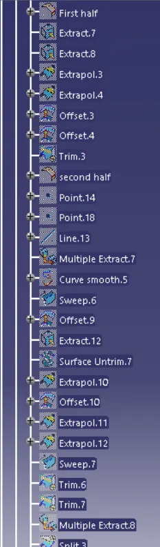
First extract all the surfaces for inclined portion of base plate.
Then untrim all the surfaces to get intersection for surfaces so that a replica can be created.
If the surfaces are not inersected then extrapolate by point continuity propagation likewise extract all the surfaces
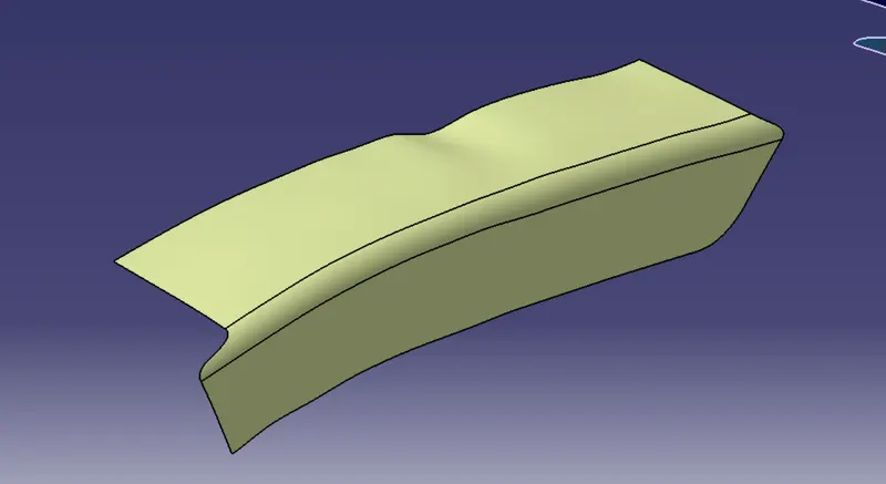
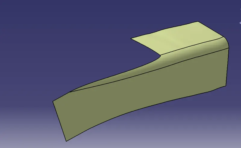
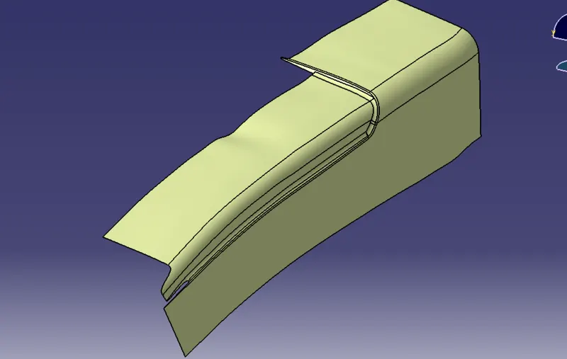
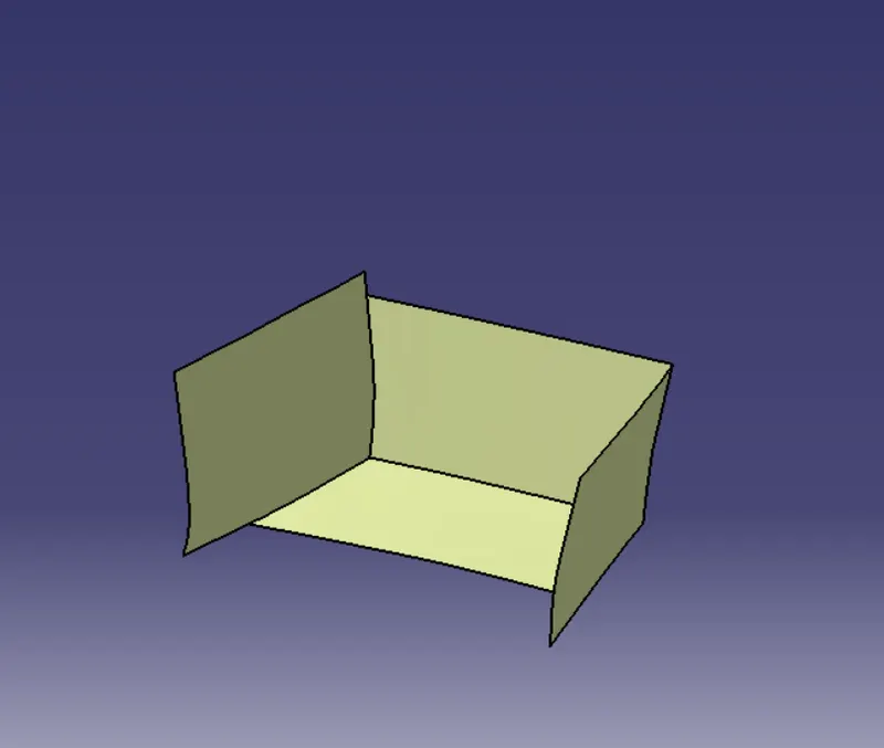
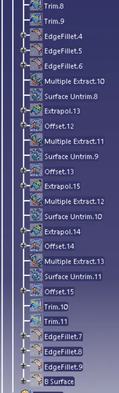
Now trim all the surfaces together to get a class B surface
\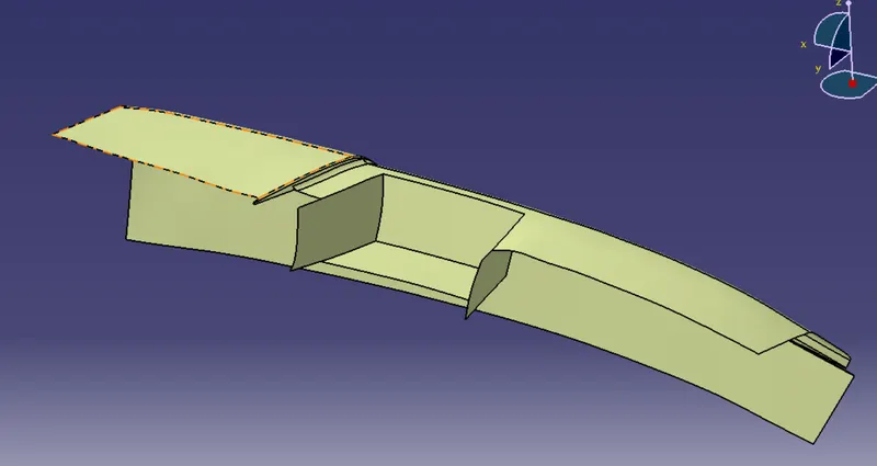
Now the fillets are to be added by checking class A surface fillets to have uniform thickness between A and B Surfaces to some fillets 2.5 should be added and to some fillets 2.5mm should be subracted accordingly.
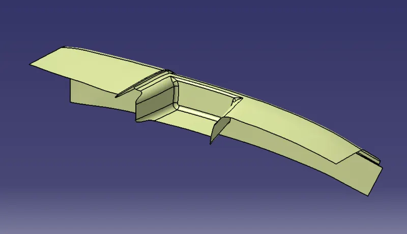
Thus whole component of B surface is created in small parts ,then joined using trim option and then final fillets are assigned
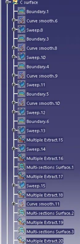
C SURFACE CREATION
C Surface is connecting surface between A and B surfaces this is where thickness of component can be seen.
Procedure:
Here C Surface will be created using the sweep command that too in small parts as the whole sweep cannot be created as surface is complicated and has fillets for sweep option use with reference to draft direction with draft angle 3 deg for surfaces which are perpendicular to tooling axis and other surfaces created with sweep option with reference to class A surface and for fillets multisection is used
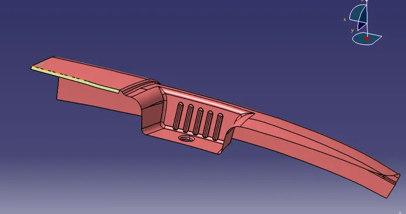
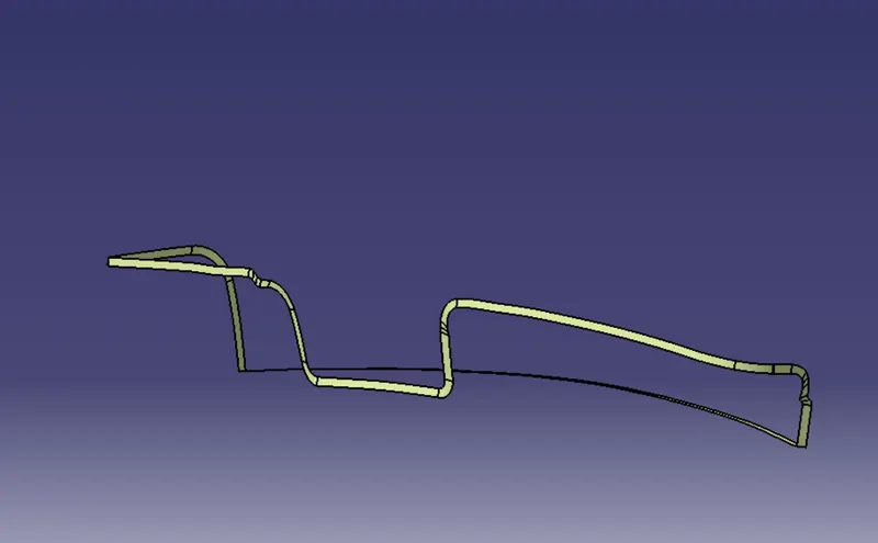
Next the surfaces are joined with class A surface to form a complete A and C
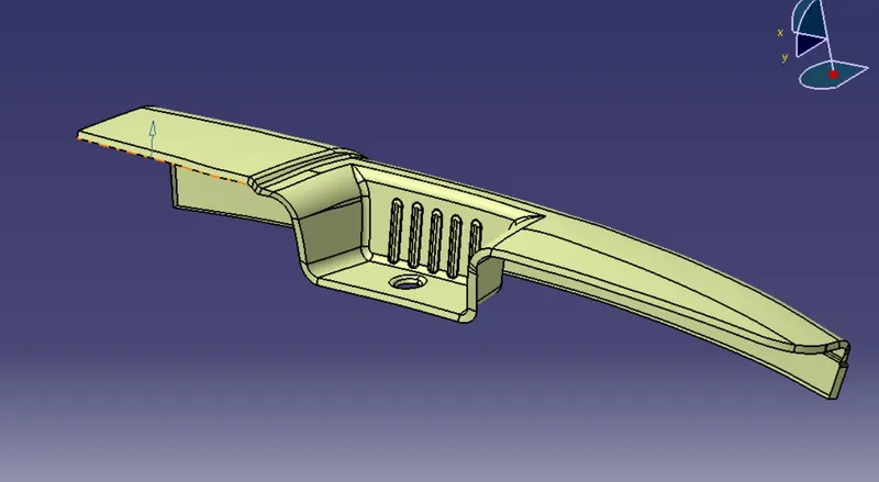
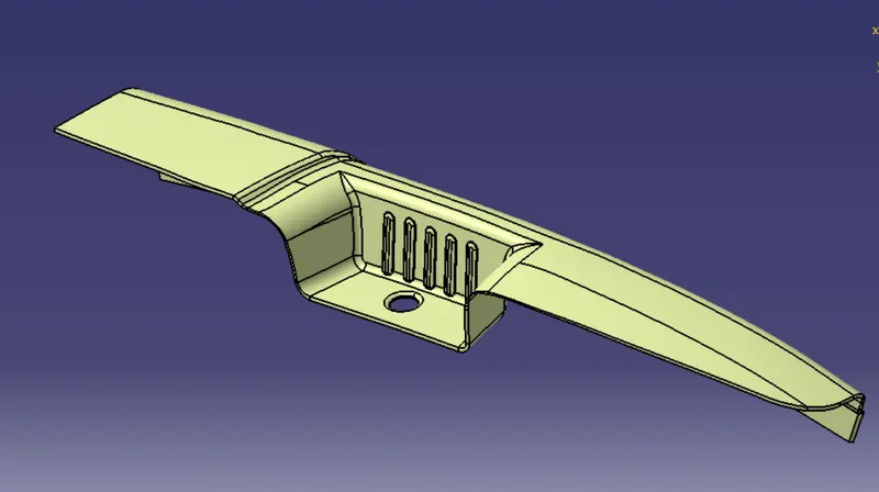
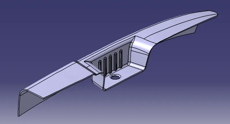
Now this joined surface is trimed with class B surface to form a complete closed surface then go to part design usse closed surface command and form a body
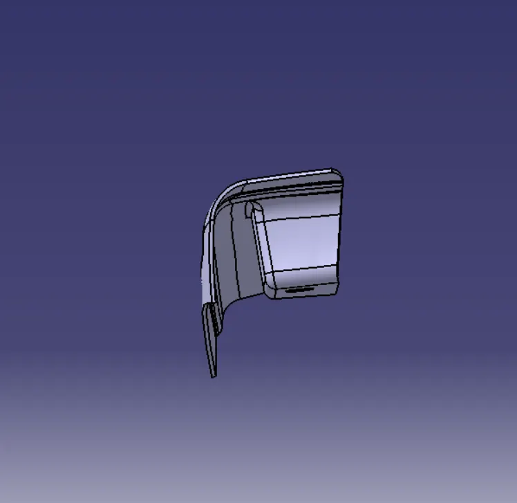
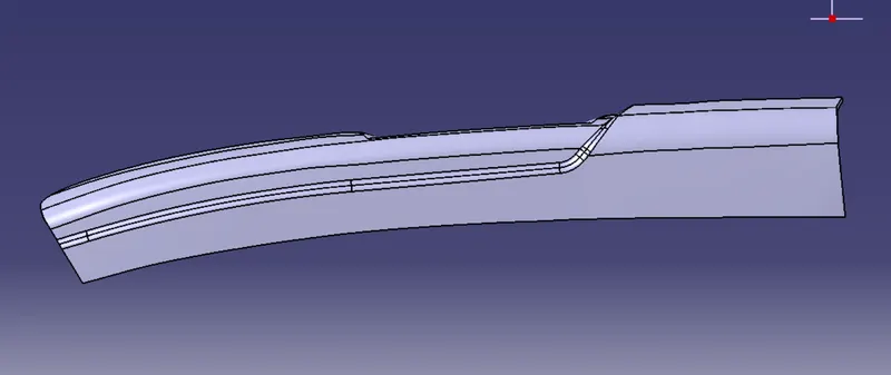
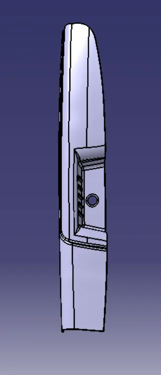
DRAFT ANALYSIS (along main tooling axis):
To perform draft analysis on the model: Go to menu bar > Analysis > Feature Draft analysis. to give draft direction use the compass and align Z-axis of it with tooling axis. Once it properly aligned , lock the draft direction. A red point shown on the screen ,select Door arm rest body and it will show us the current of the model . then go to display tab on draft analysis and select the first option under it colour scale and it will show draft value .set the value to 2.9 deg under the colour scale variat and press ok.here analysis can be done in two ways quick analysis and full anaysis we choose quick analysis.
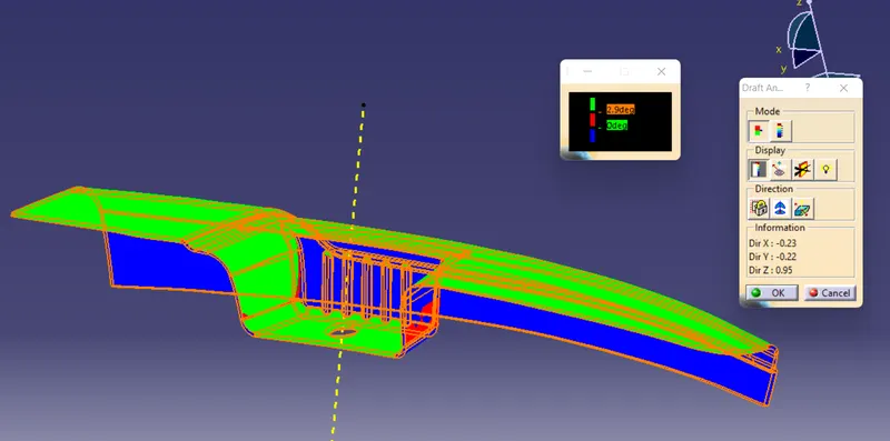
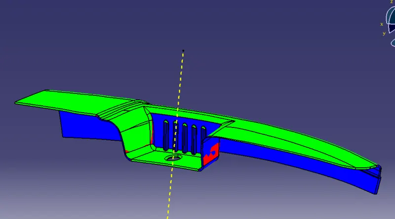
Here draft analysis shows
- The Green colour is drafted walls above 2.9 degree.
- The Red colour is drafted walls above 0 degree.
The analysis shows the drafted walls of Door arm rest are above the par of 2.9deg which is permissible to manfacture in injection modeling. except some surfaces which are to modified and we can see Screw boss and dog house are above 0 deg draft angle.
DRAFT ANALYSIS (along Side core axis):
To perform draft analysis on the model: Go to menu bar > Analysis > Feature Draft analysis. to give draft direction use the compass and align Z-axis of it with tooling axis. Once it properly aligned , lock the draft direction. A red point shown on the screen ,select main body and it will show us the current of the model . then go to display tab on draft analysis and select the first option under it colour scale and it will show draft value .set the value to 2.9 deg under the colour scale variat and press ok.here analysis can be done in two ways quick analysis and full anaysis we choose quick analysis.
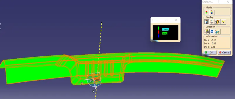
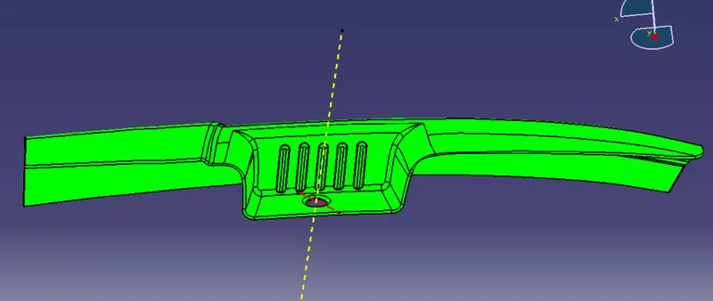
Here draft analysis shows
- The Green colour is drafted walls above 2.9 degree.
- The Red colour is drafted walls above 0 degree.
The analysis shows the faces which arent cleared in main tooling axis direction were cleared and are feasible for manfacturing
Thus draft analysis done.