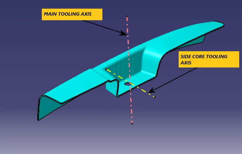
Door Arm Rest Week 8 Challenge
DOOR ARMREST
AIM
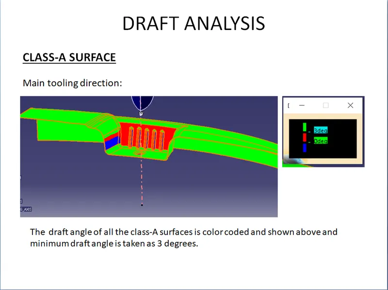
This challenge aims to create the solid body of the given class-A surface of the door armrest by defining the tooling direction and performing a draft analysis of the final solid.
PROCEDURE
Inspection of A-surface
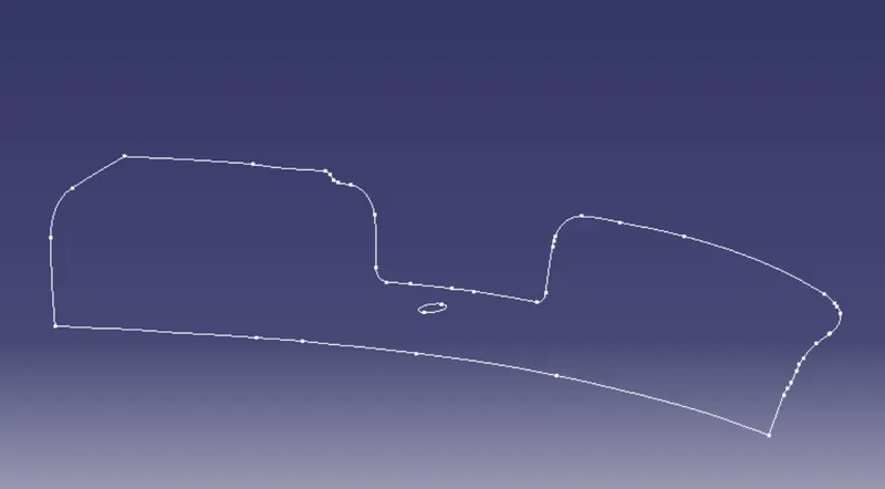
The first step in designing any component is to check the given surface. The given class-A is visually validated using the boundary command, which helps find any patches on the given surface.
Defining the tooling direction
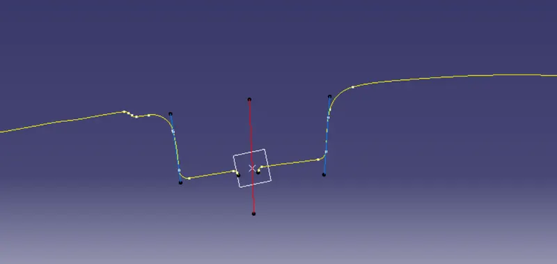
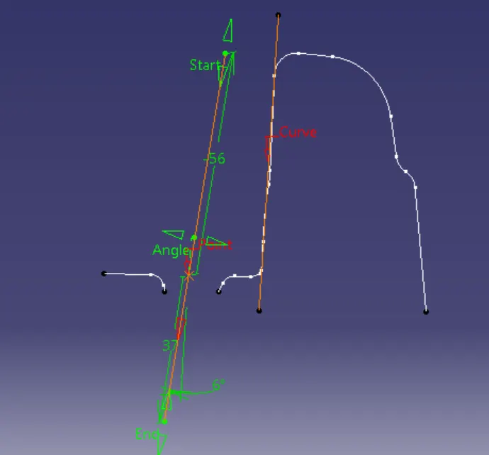
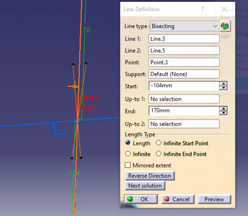
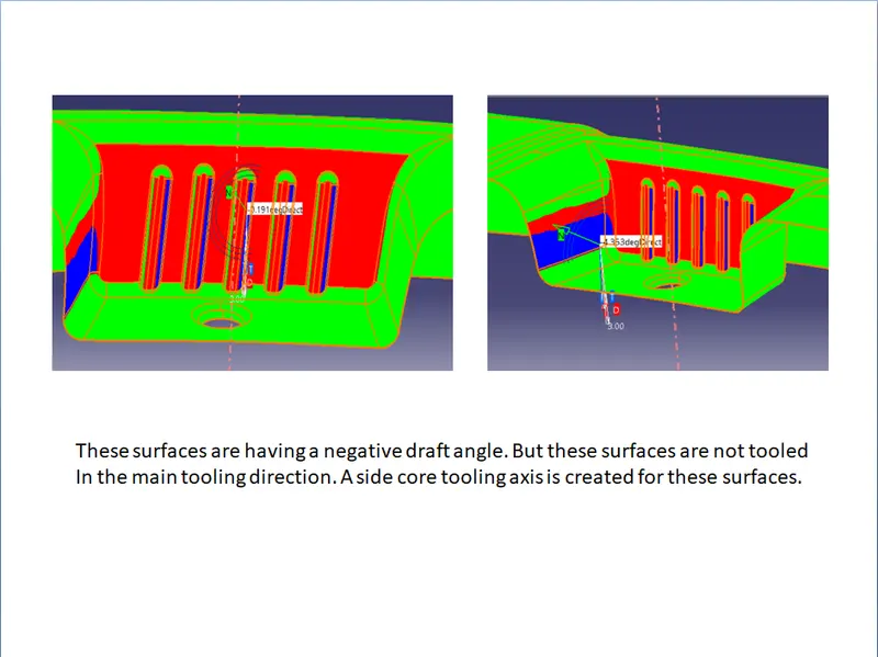
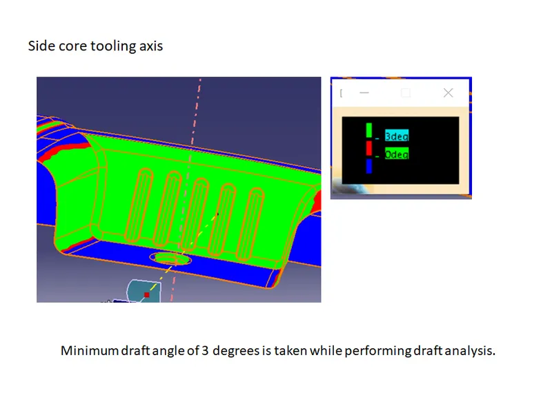
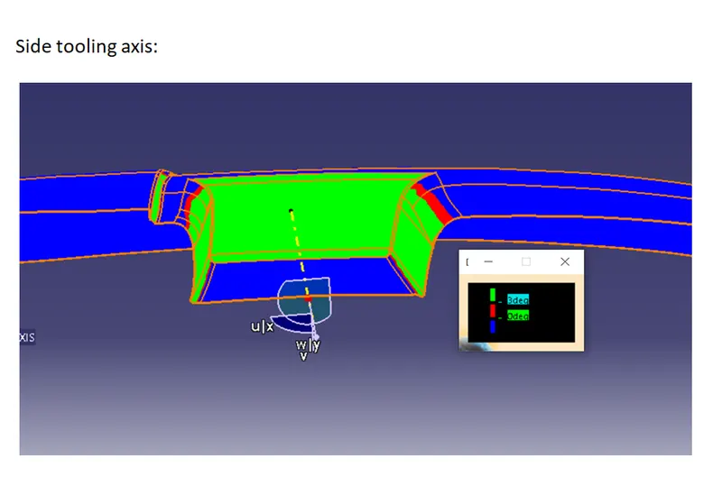
By looking at the given class-A surface, it can be seen that most of the components can be tooled in the direction perpendicular to flat faces. Also, in manufacturing a plastic component, it is best if all the holes in the component are getting cleared in the main tooling axis. An initial direction is assumed, and the surfaces which might create a problem are identified, and by using intersection, the edges of these surfaces are created. A line bisecting these edges is created along the dummy tooling direction, and for the other surface, there is only a single edge; a line is created at an angle of 6 degrees from that line. These two lines are bisected along the dummy tooling direction to get the main tooling direction.
Creation of class-B surface
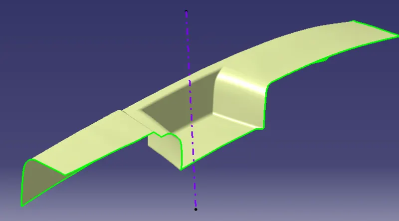
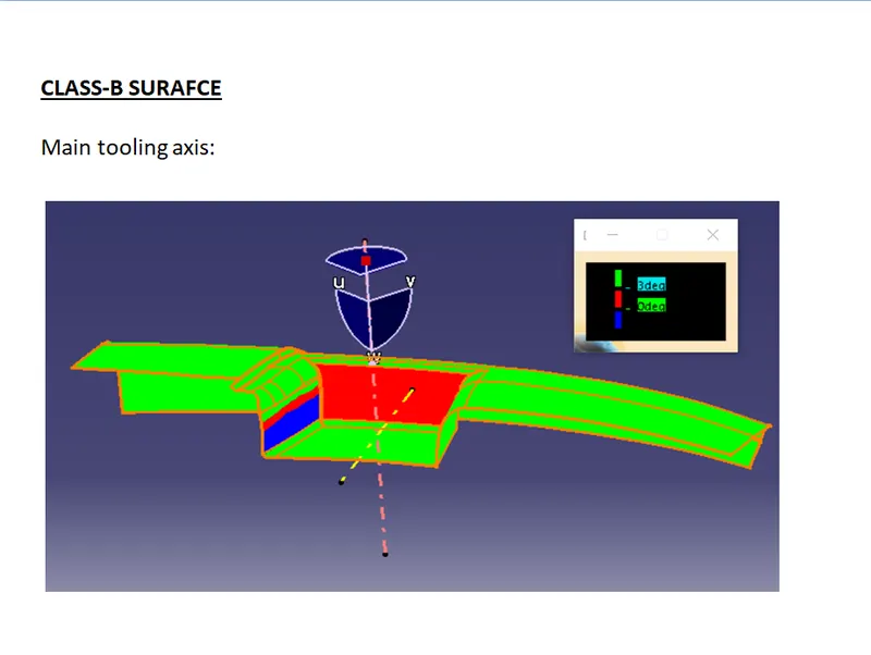
All the class-A surfaces which are not fillets are identified and extracted. These extracted faces are now untrimmed to get the original surface using the untrim command. One surface is wholly filleted for the given surface and must be generated entirely again. This is done by creating a sketch consisting of a line tangent to one of the fillets. The fillet edges are extracted using multiple extracts and taking this extract, and the sketch as input sweep command is applied to get the surface. This surface is joined to the flat untrimmed face using the blend command. All the surfaces are joined using the join and trim options (necessary edges are extrapolated). These surfaces are offset by 2.5mm, and required surfaces are trimmed. The fillet values are calculated from the class-A surface, and appropriate values are given to fillet the sharp edges of the B-surface.
Creation of C-surface
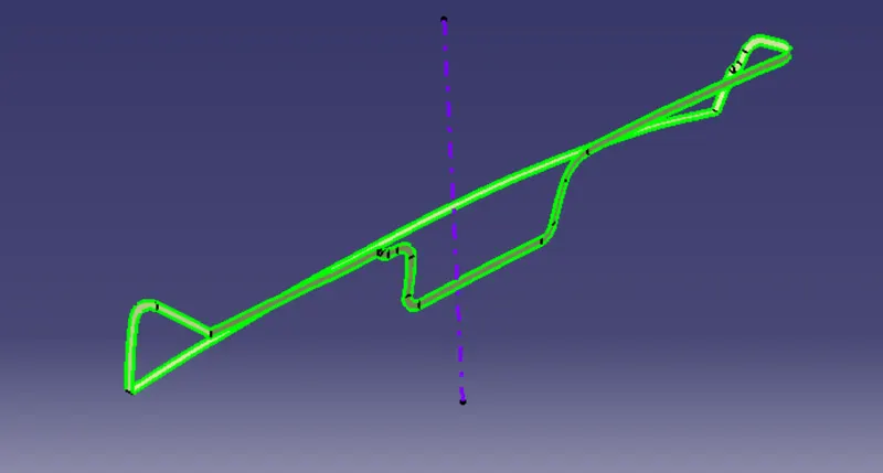
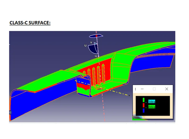
Creating a C-surface for this particular component is done by dividing the A-surface boundary into smaller segments. These smaller edges are used to produce the C-surface by using the sweep command. All the segments of the C-surface are extrapolated to touch each other and trimmed off to get a single C-surface.
Converting into a solid model
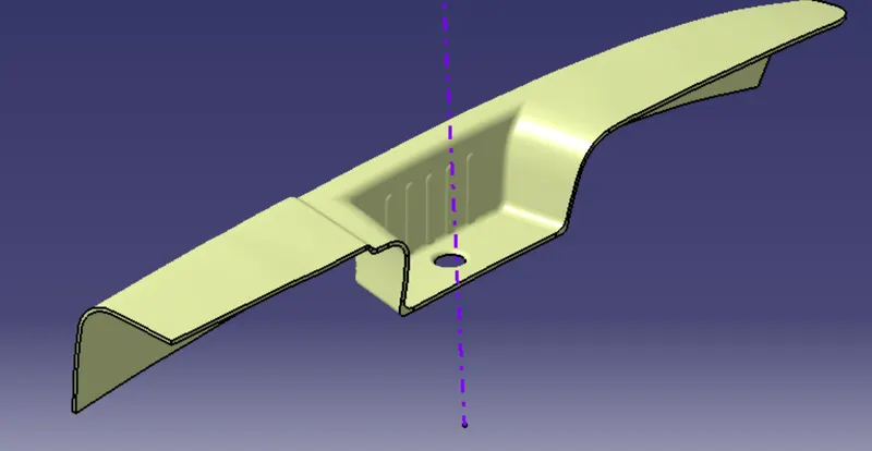
This single C-surface is joined to the class-A surface using the join option, and the B-surface is extrapolated to touch this Joined surface. By using the trim option, a closed surface is obtained. This closed surface is converted into solid using the closed surface feature in the part workbench.
FINAL TRIM
Draft analysis
FINAL MODEL: