Door Arm Rest Week 8 Challenge
Design of arm rest using and performing draft analysis
Objective:
- Design class B and Class C surface from the given Class A surface
- Perform draft analysis on the Class A surface and the final solid part
- Make a solid part from the complete closed surface with thickness on 2.5mm.
Given class A surface:
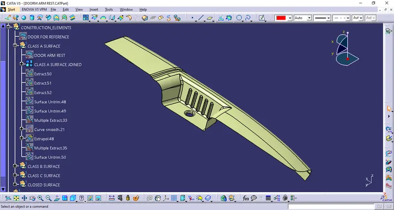
Performing draft analysis on the surface:
As the surface has two parts that need to be moulded. It will need to drafting axis
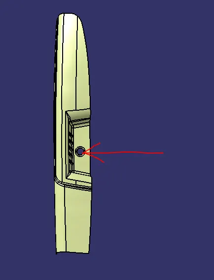
First to draft to mould the door handle cavity, it can be done in the direction shown in the image:
Second is to mould the main arm rest:
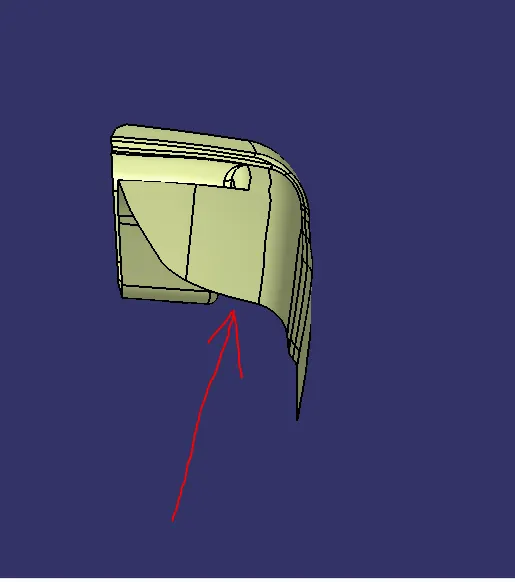
To perform draft analysis tooling axis where created
1. Tooling axis for door handle cavity:
The base of the cavity was extracted and then offseted to almost the center of the cavity:
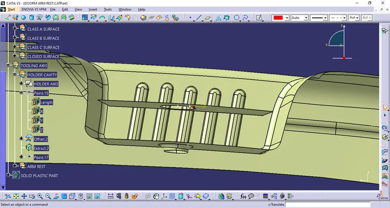
A point is created on the center of the offseted surface and an axis sustem is created on the point, this point and axis are used for making the sketch of the axis:
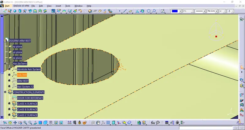
Intersection sketch is made of the cavity:
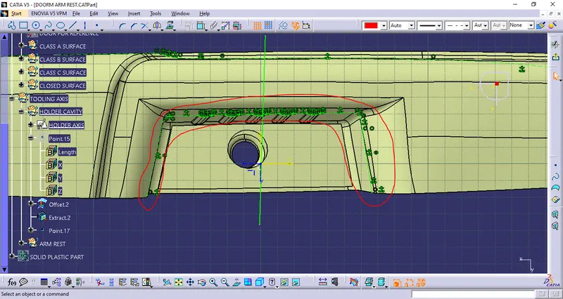
Usign bisceting line command a line is created as the tooling axis.
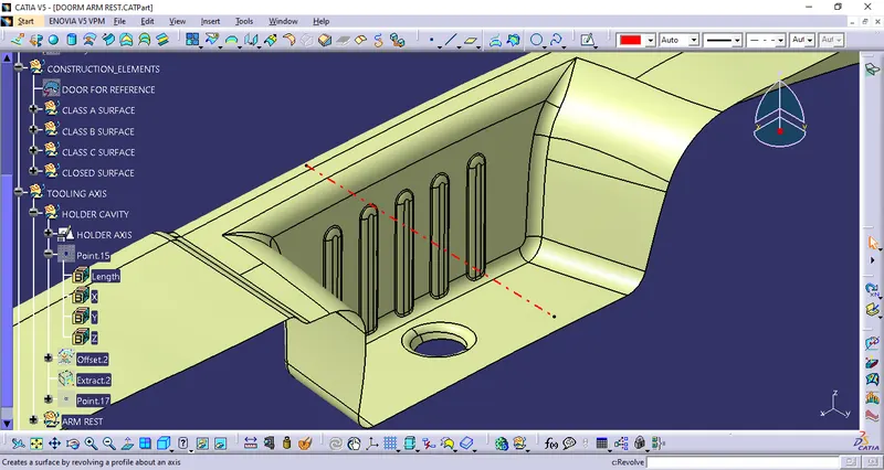
2. Making tooling axis for the main arm rest:
Similiarly a point and a axis system is created on the surface of the main arm rest :
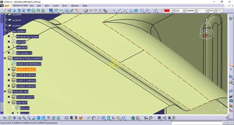
using intersection, a sketch is created at the intersection on the axis system and the class a surface and a line is created using a bisect command.
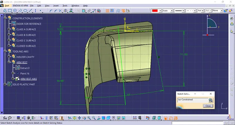
Therefore the tooling axis for the arm rest is created:
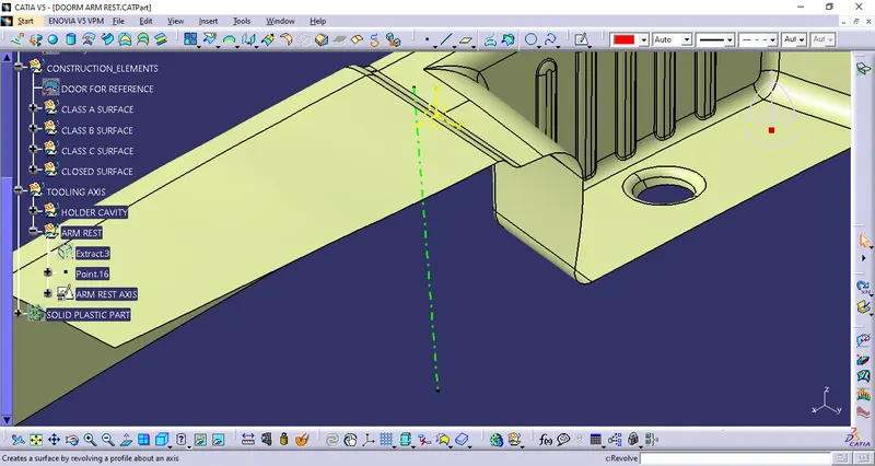
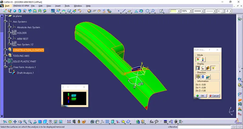
Draft analysis:
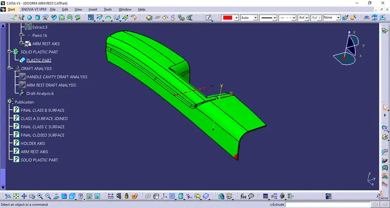
Using the drafting axis we can see that the arm rest is green in color:
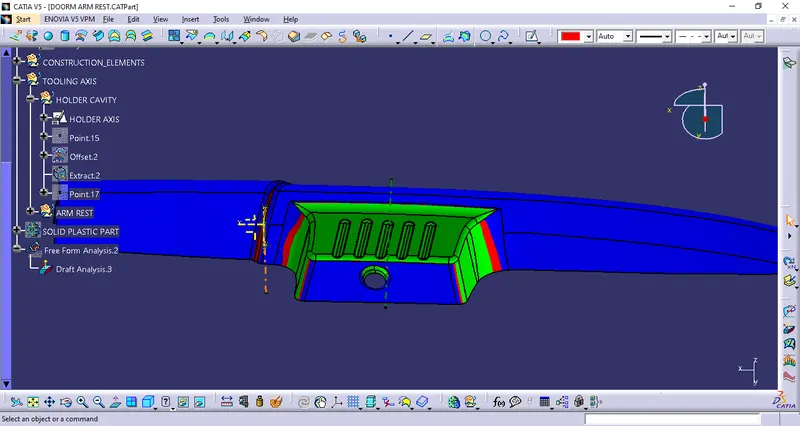
Draft analysis for the handle cavity:
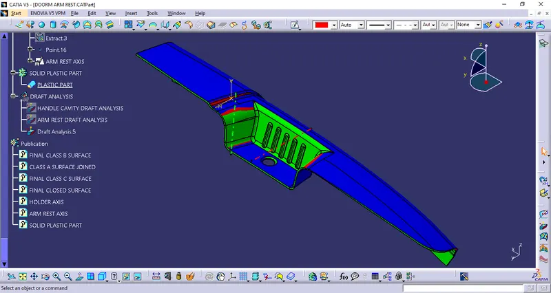
Using free form analysis command, we can see that the mould cavity clears the draft analysis.
Creating a Class B surface:
The class B surface was created usign the class A as reference
Handle cavity Class b surface:
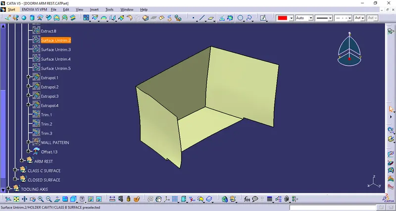
The main arm rest is divided into the first surface, second surface and a connection surface:
First surface:
The first surface is a combination of the side wall and the lower surface of the arm rest
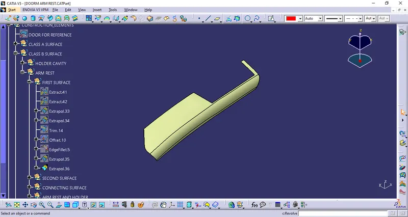
Second surface:
The second surface is the combination of the other wall and the upper surface of the arm rest
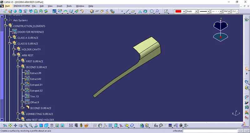
Connecting surface is the surface between the above two surfaces:
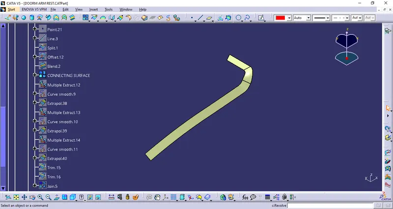
All the surface are trimed together and joined to make a final surface:
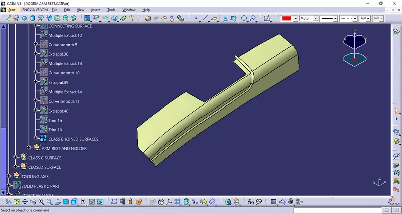
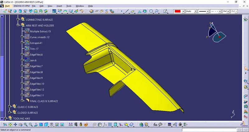
The final class B surface is made by joining the Handle cavity and the above surface and adding the fillet, keeping in mind the 2.5mm thickness of the part.
NOTE: The excess part is later trimed off when making a closed surface
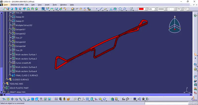
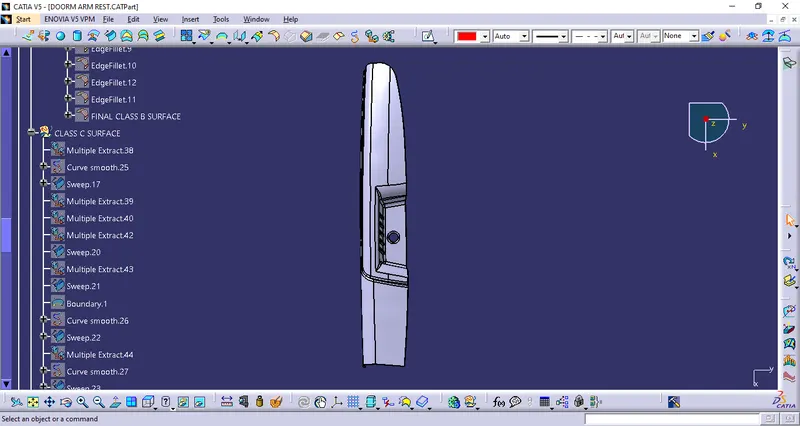
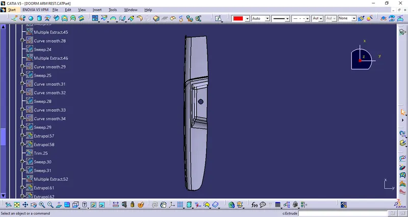
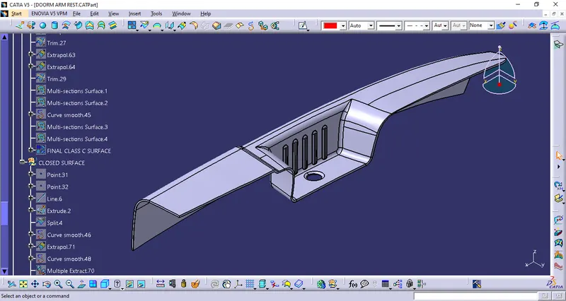
Class C surface:
This surface is made by using the sweep option and multi section surface:
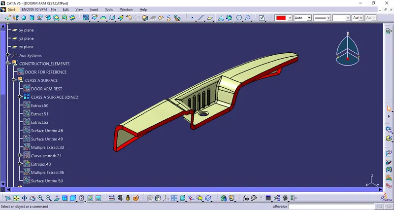
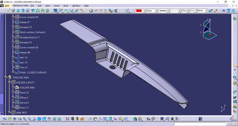
The final closed surface:
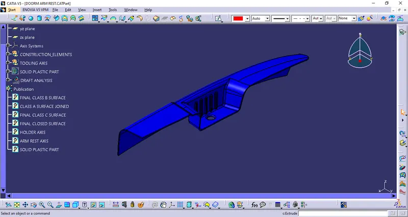
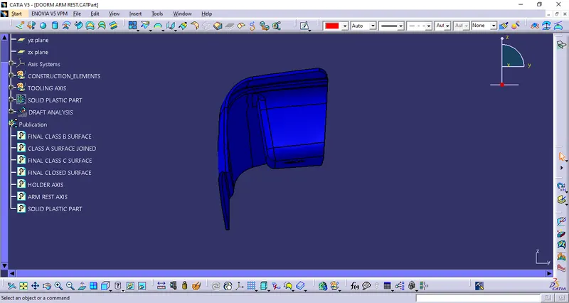
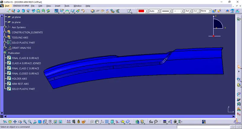
The closed surface is then made into a solid part by using the closed solid command in the part design
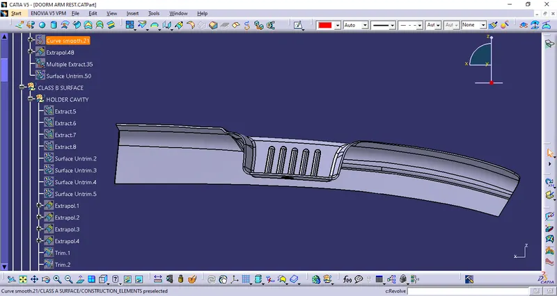
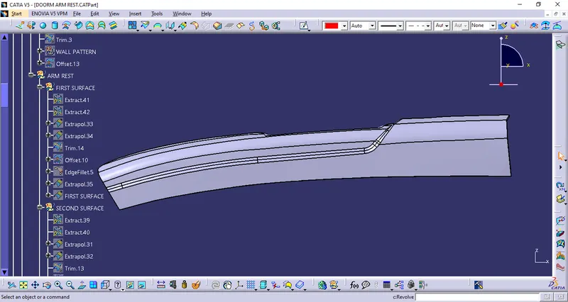
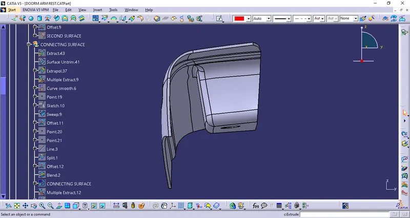
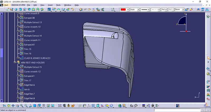
Final solid part with expanded feature tree:
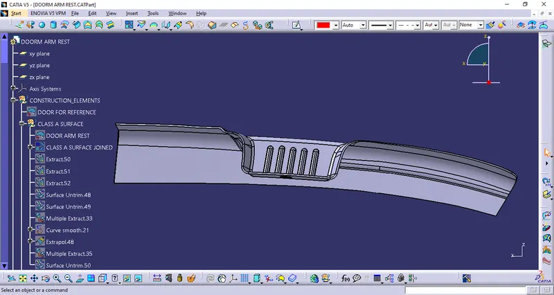
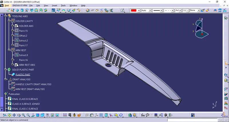
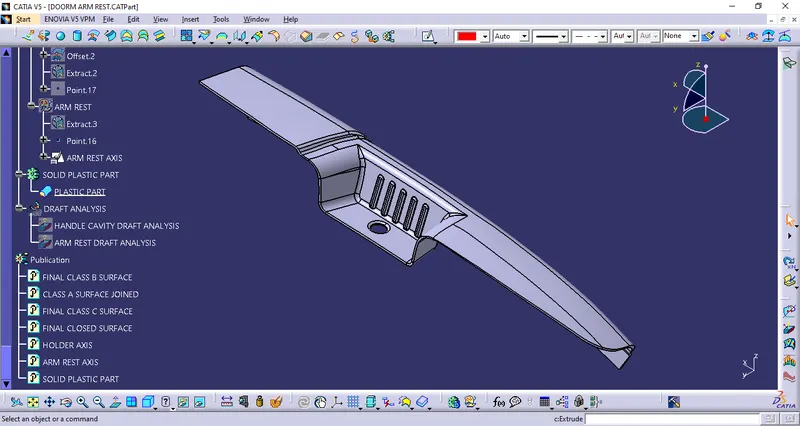
Draft analysis of the solidpart
Door handle cavity:
Using the red tooling axis
Draft analysis of the arm rest:
Using the green tooling axis
Conclusion:
For the given Class A surface draft analysis was done using the created tooling axises. The tooling axis and the draft were found satifactory. Class B and Class C surfaces were created using the given class A surface, a closed surface was made. The closed surface was used to create the solid body using the closed body command. The draft analysis was also performed on the given solid body to check for the tooling axis and the draft satisfaction.