Door Arm Rest Week 8 Challenge
DOOR ARM REST DESIGN &DRAFT ANALYSIS
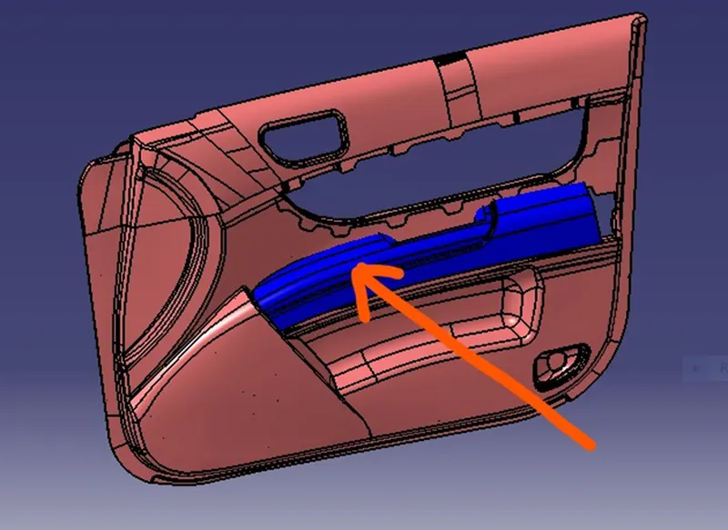
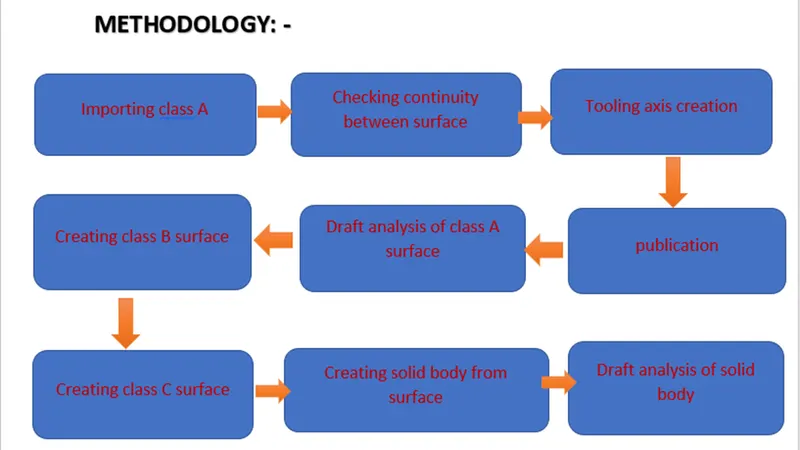
AIM- Creating the door arm rest component with the help of given class A surface with 2.5mm thickness. To Create the door arm plastic component through the given class A surface. To begin with the tooling axis for the given class A surface should be created meeting the required of the draft angle and also create the class B surface and C surface.
PROCEDURE-
STEP 1 – First we get the class A surface
CLASS A SURFACE- In Automotive design a class A surface is any set of freeform surfaces of high efficiency and quality. Class A surface is done using computer aided industrial design application. Class A surface modelers are also called ‘’DIGITAL SCULPTORS’’ in the industry. Industrial designer develops their design stylish through the class A surface.
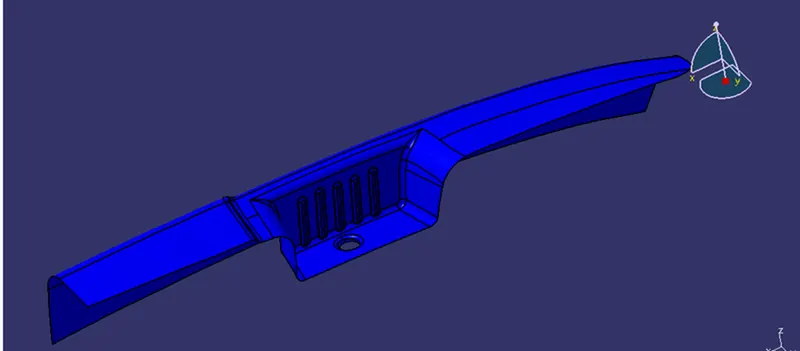
DESIGN CHECK ON CLASS A SURFACE: First of all, we have to check continuity of given class A surface to ensure class a surface is proper joint or no discontinuity present. This can be done using join or boundary options. Below images show the surface is continuous boundary there is no discontinuity.
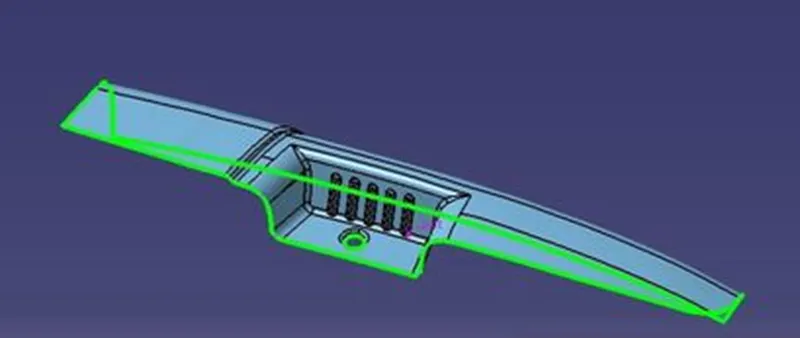
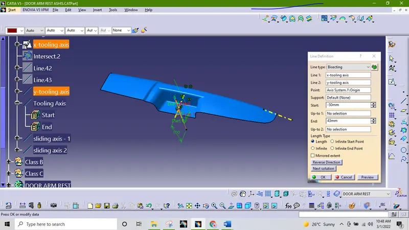
TOOLING AXIS CREATION USING BISECTING METHOD-
- Extract the base of the using multiple extract command. create a point using point on surface option.
- Insert Axis system at that point.
- Then creating intersection curves in X direction and creating side lines on that curve and then creating the bisecting sketcher.
- Also create curves in V direction and creating side lines on that curve and here we have only one side walls so we will create line passing through the point which we created in above steps at an angle of draft in sketcher. Angle taken is 3-6 degree to get all faces feasible with tooling axis.
- Then creating bisecting line through X and Y direction tooling lines.
- Creating tooling axis in Z direction.
- For creating side core tooling axis, we will extract side face and create point and a add anormal line tooling axis.
B SURFACE CREATION-
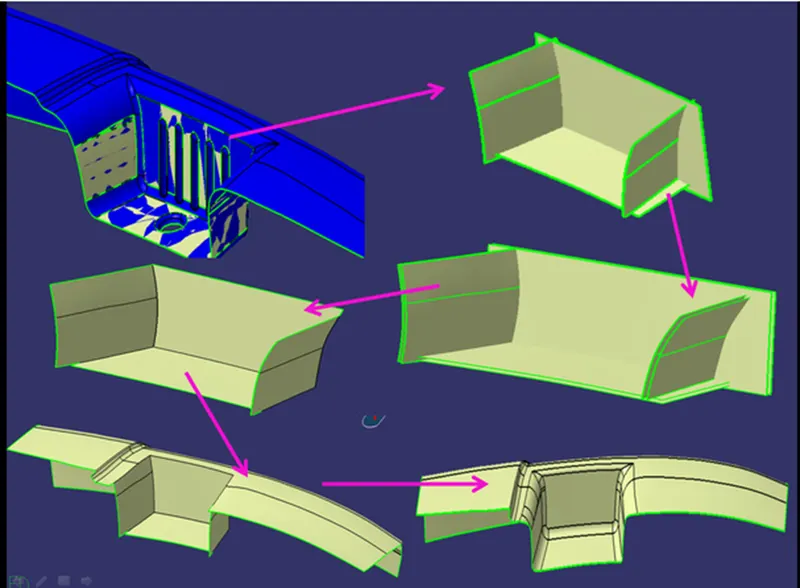
- Now we will start create of B surface. First, we will extract the faces untrim it. We will join the two surfaces together.
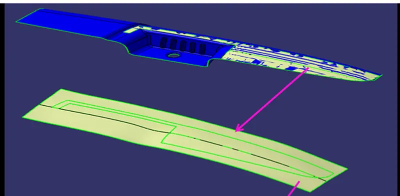
- We will extract the back surface and extrapolate it.
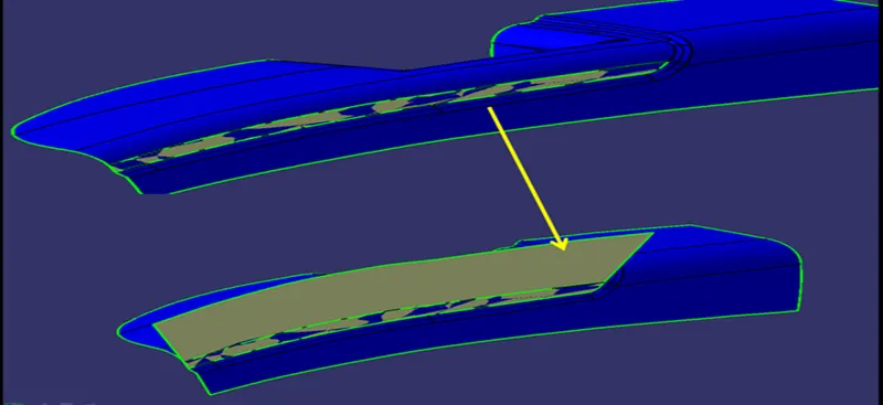
- We offset these surfaces 2. 5mm.Trim the offset surface. Add fillet at the following design rule.
- We extracted surface similarly which surface are required then if needed extrapolate them and offset each surface2.5mm. Then trim them and if required then giving required fillet.
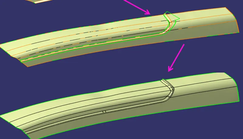
- After that we will extract all the surface of walls. untrim them and giving offset, extrapolate it. trim all the surfaces to get required shape. Then trim with the main surface and adding fillet.
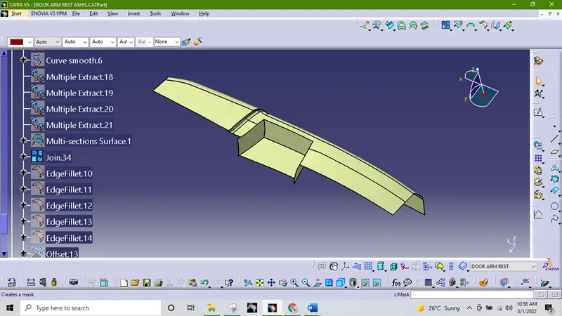
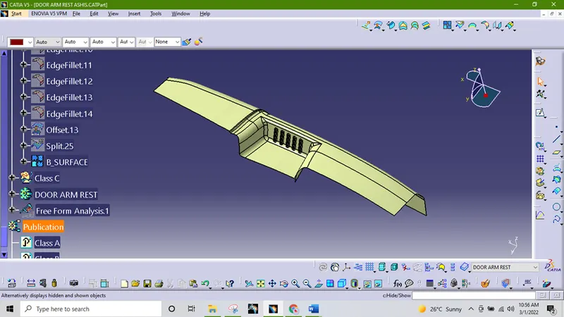
C SURFACE CREATION-
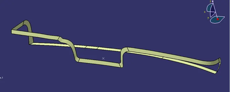
- Take outer boundary of class A surface using boundary command.
- Use smooth curve
- Use sweep command to create surface using tooling axis and draft angle as 3 degrees.
- Create the back surface using 90 degrees
- Using multi section surface to join the surfaces.
- Create points and lines to split the surfaces where needed.
- Join the split surfaces using multi section surface,
- Using extrapolate option to extrapolate the surface and then trim them.
FINAL BODY CREATION-
- Trim class c surface with class b surface that is the surface class b and c surface without hole.
- Creating the hole.
- After that join all the surface, Class A, Class B& Class C.
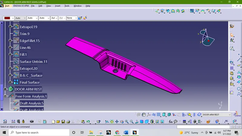
SOLID BODY CREATION
- Change the part workbench.
- Create body
- Close the surface using the last join.
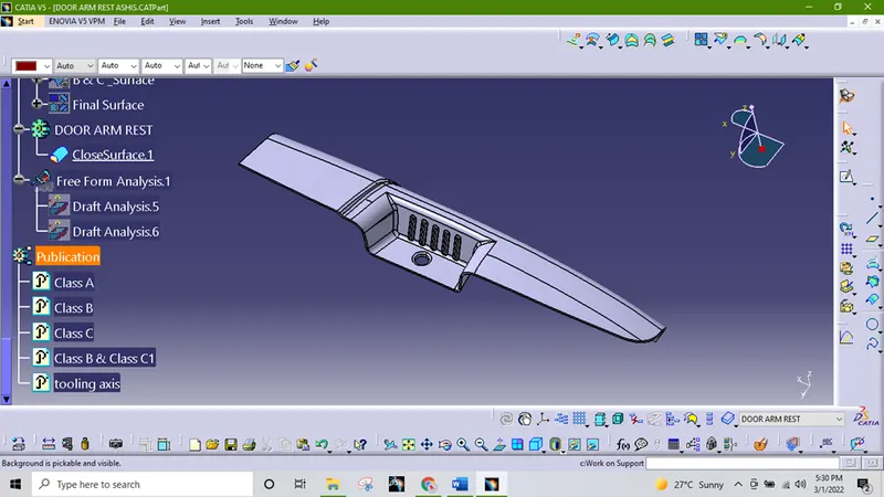
DRAFT ANALYSIS
- Final plastic parts are the nominal draft angle is 3 degrees but even 7degree is allowed for the subassemblies like ribs and slots.
- Insert< Analysis< Feature draft analysis
- First the compass is moved to the part which used to define the tooling axis new current draft direction then lock the draft direction using the lock icon.
- The color of the chart indicates the draft if the color is indicated that means the part passes and used for further operation.
- By using the analysis under the running point icon, we can check draft angle at the various surface of the component.
- If the surface satisfied the draft angle, then it shows the green color if not appears in red color.
Below image is the draft analysis on A surface with main tooling axis. As we can see most of the areas are green that means it clear in main tooling direction. But bason part some surface are not green this means it not clear in main tooling axis.so that’s why create side core axis.
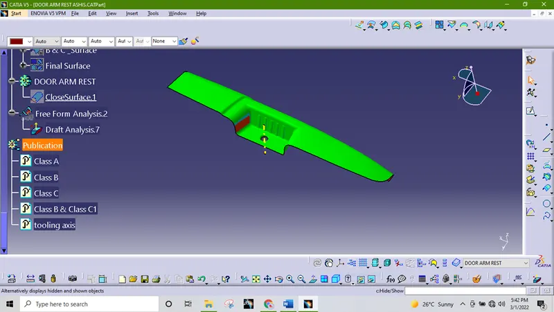
Below image of DOOR ARM REST Draft analysis with main tooling axis.
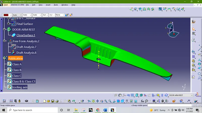
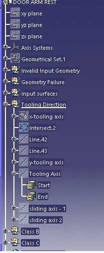
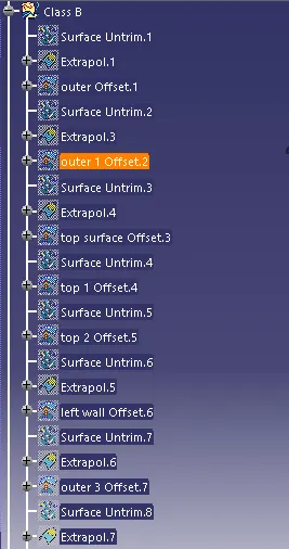
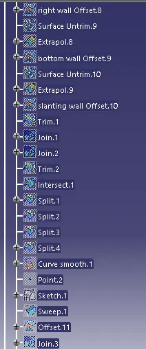
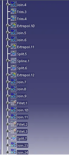
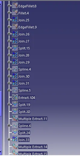
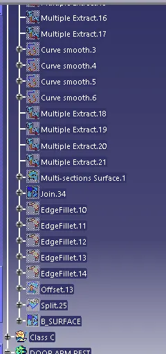
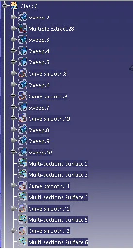
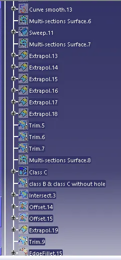
TREE
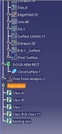
DESIGN VIEW
ISOMETRIC VIEW
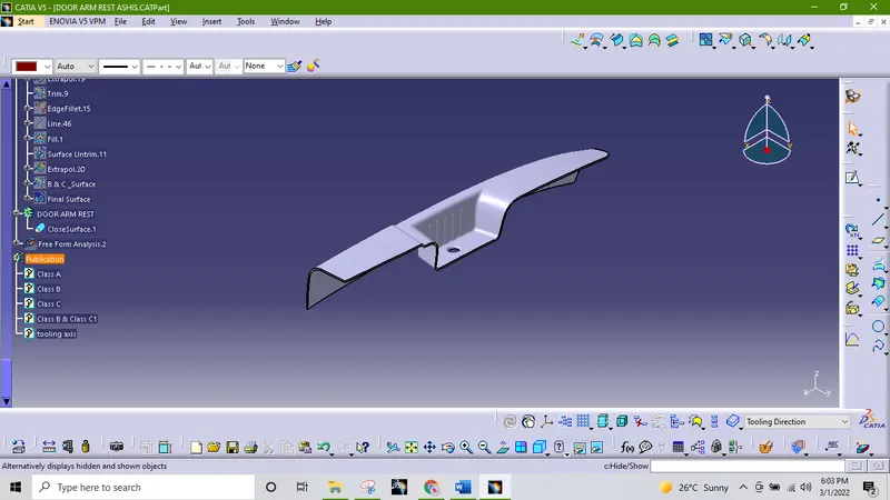
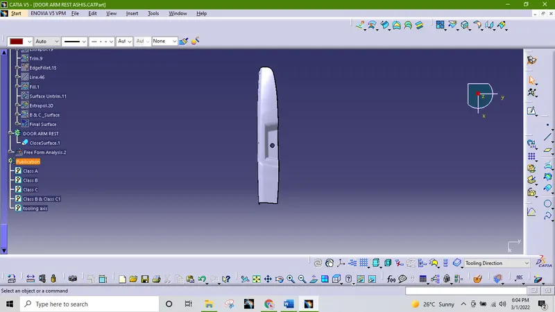
FRONT VIEW
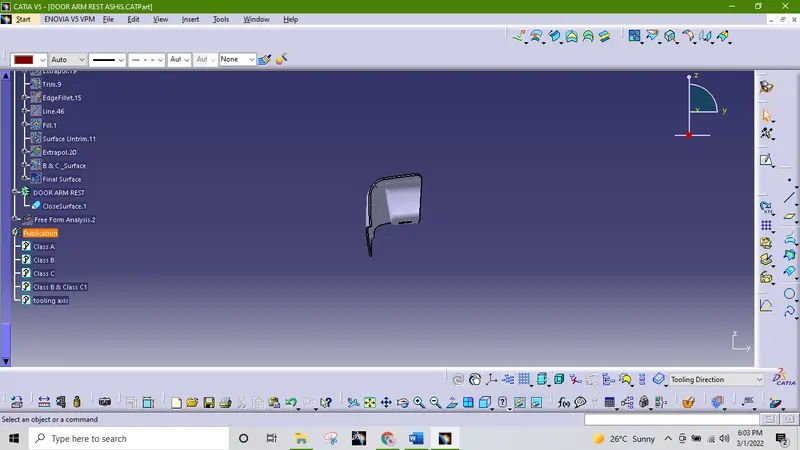
RIGHT SIDE VIEW
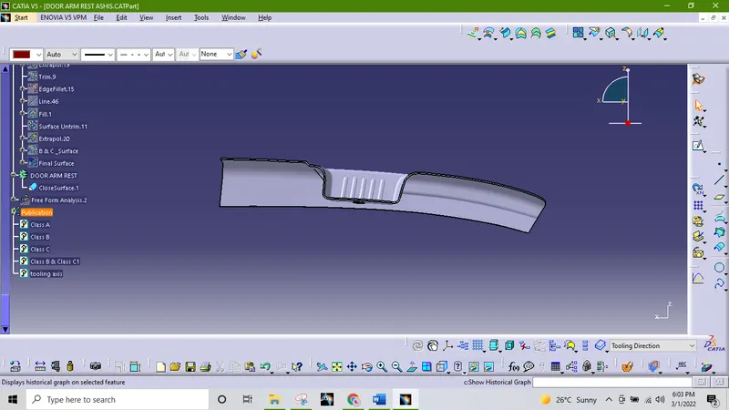
TOP VIEW
CONCLUSION
Successfully we create the final body and perform draft analysis. We learn from this project Extracting tooling axis by sketch, blend surface, smoothing boundary, draft analysis and fixing error and others etc.