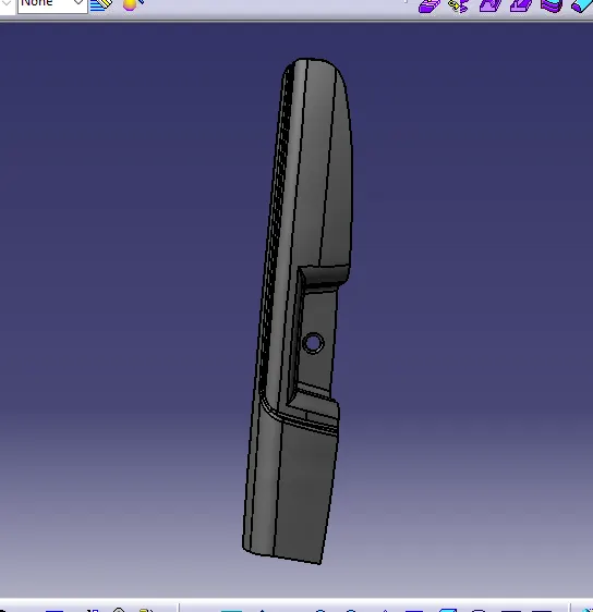
Door Arm Rest Week 8 Challenge
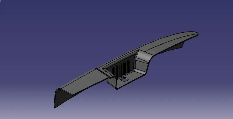
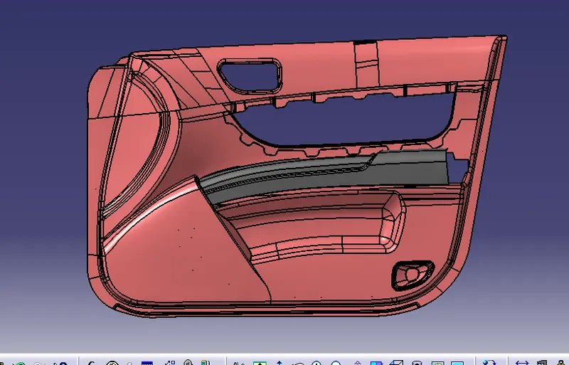
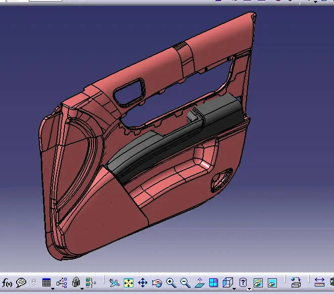
Door arm rest from Class A as Input – Automotive plastic component
Aim: Creation of Door arm rest and add thickness to It.
Objectives:
- Create a class B and class C surface for the door arm rest using the given class A surface.
- Use the given Class-A For reference
- Use the close surface feature to make a solid body from the surface.
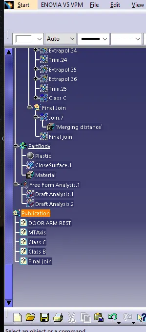
- Use the publication option and use the class-A, class-B, class-C surfaces and the tooling axis.
Procedure:
Step 1: Design Check (Pre check) on received class-A:
- After receiving the class-A for the Door arm rest Check for the connectivity of the surfaces on it.
- Use boundary operation and disassemble.
- Check for Discontinuous surfaces.
- The check is over if any discontinuities do not arise.
Step-2: Determine the Tooling axis:
- Extract a plain surface and create a point on its center for axis system creation.
- In this case Z axis can be a possible Tooling Axis direction.
- Create a Sketch on the XZ plane of the axis system and use intersect 3D to plane option to get the sketch.
- This line is used for tooling axis for X.
- Do similar steps for YZ plane.
- The tooling created here is Y tooling.
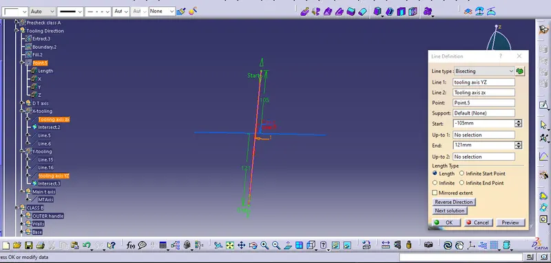
- Then use Bisecting line option to bisect both the tool clearing axis and pass the bisecting line through the origin.
- This line created here is the main tooling axis.
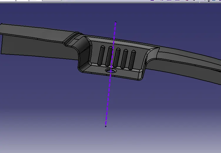
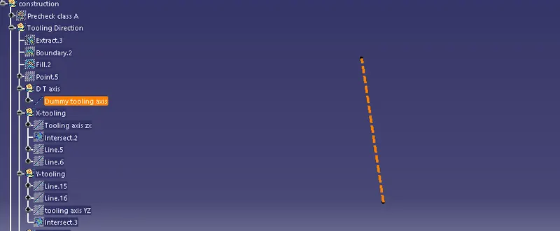
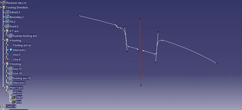
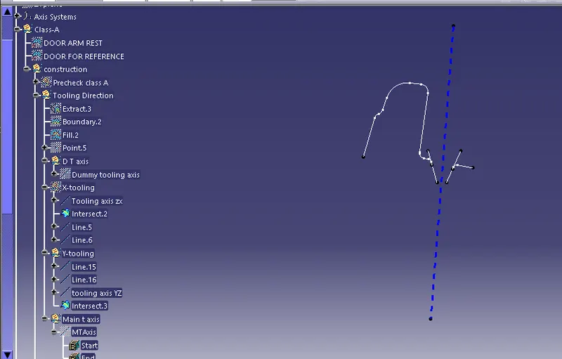
Step 3 Draft analysis on class-A and possible creation of side tooling axis:
- Change View Mode Customization to material mode.
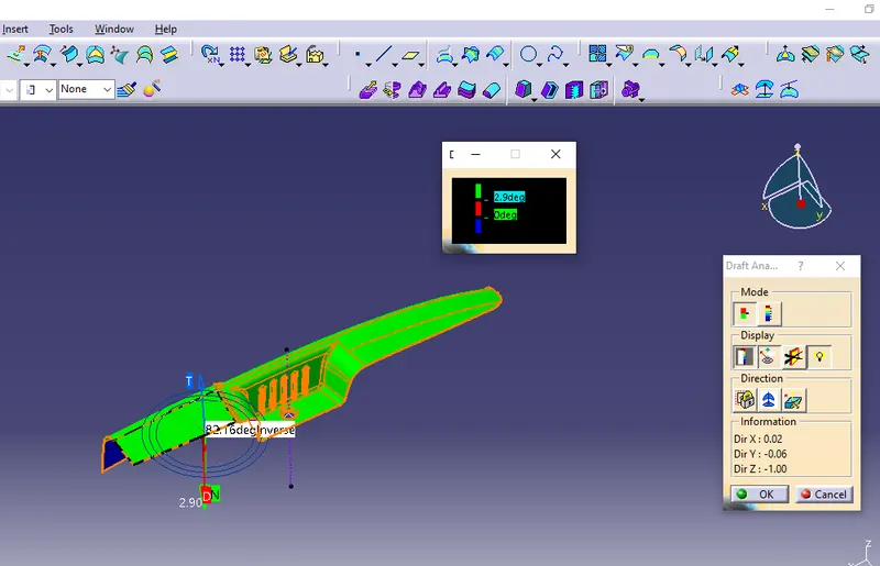
- Go to INSERT> ANALYSIS> FEATURE DRAFT ANALYSIS and move the compass to the tooling axis.
- The input Class-A also has walls having negative angle to the tooling axis.
- This can be an issue while manufacturing the component as it would be very difficult to draw from the molds.
- So, the design needs to consider various Side tooling options.
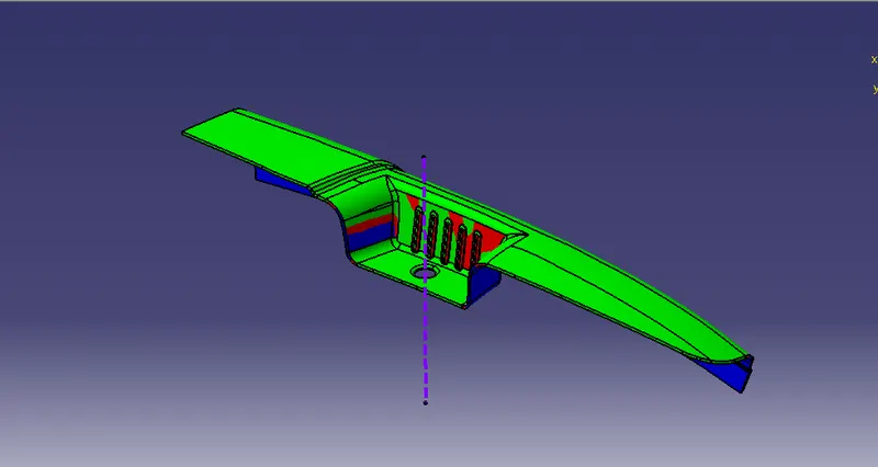
- The minimum draft angle is 3 deg, here red is zero, Green is above Zero deg, blue is below zero. So, try to keep that draft angle in positive.
Class A Draft analysis:
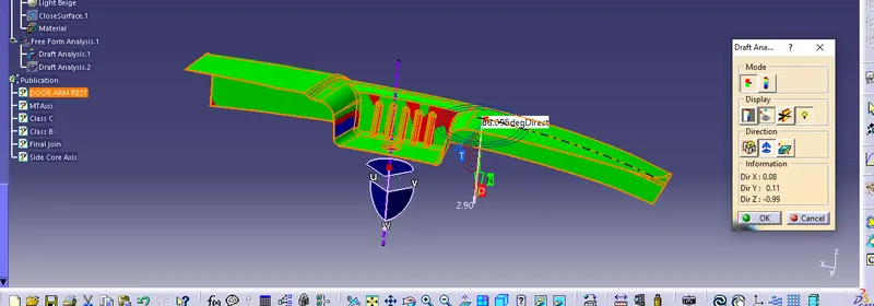
Final Draft analysis:
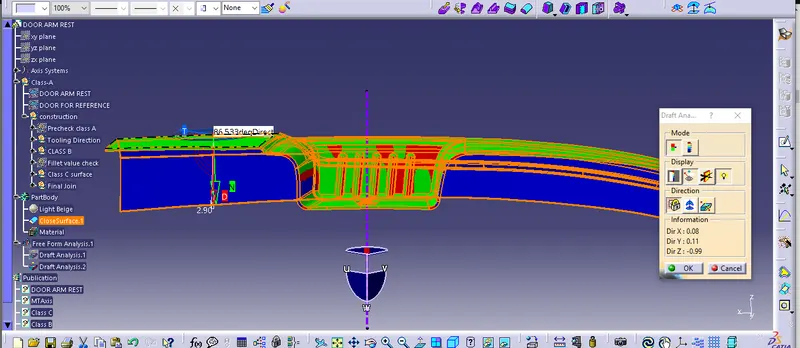
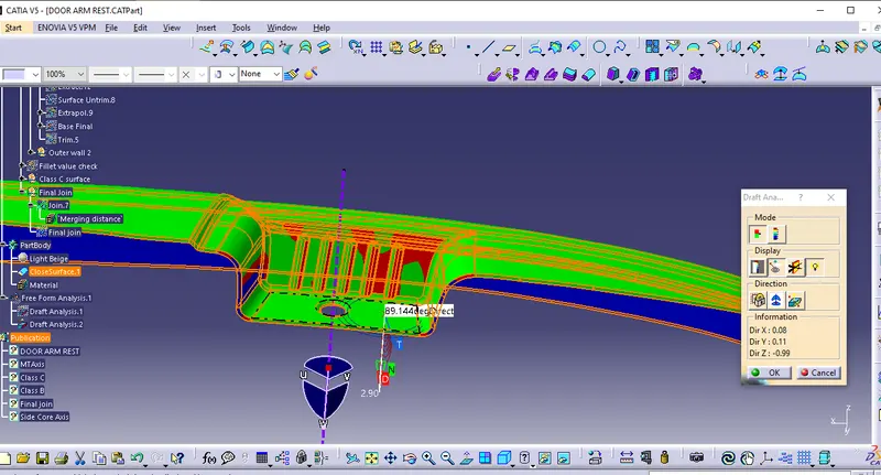
Step 4 Creating Class-B surface
- First extract all the necessary flat surfaces from the class-A surface.
- Then untrim these surfaces to get intersection for surfaces so that replica can be created.
- If the surfaces are not intersected, then extrapolate by point continuity propagation is used to make these surfaces have an intersection between them.
- Then offset all the surfaces by thickness of 2.5mm as given to obtain B-surface.
- One surface where you wont able to extract the surface because of the fillet in that case extract the boundary of that surface and create a guide line taking one boundary as tangent curve reference in line command and sweep it.
- Next surface trim is used to get class-B surface.
- Lastly measure the fillets from class-A surface and give to the surface according to the formula.
Fillet:
(If it is inward A surface then: Radius = A surface fillet radius – Thickness of the component (2.5mm))
(If it is Toward B surface; Radius = A surface fillet radius + Thickness of the component)
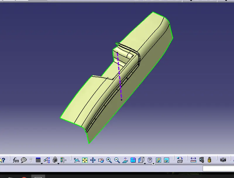
Step 5 Creating Class-C surface
- Class-C surface is where the thickness of the component lies, it is joining surface Between Class-A And Class-B.
- For creating Class-C surface we are using Sweep command most of the cases and for that the boundary lines are obtained from the class-A surface.
- All boundary lines are sweep with draft direction since all the surfaces must have a draft angle of minimum 3 deg so that component eject easily from molding. Also, the tool axis is used as the direction of the sweep.
- But for some cases like complicated curves, we use muti-section surface command
- Next the swept surfaces joined with the Class-A surface to a complete A and C surface, (Note- Merging distance kept at 0.003mm to avoid any gaps)
- Still if there is any one, we can do extrapolate A surface by 0.5mm and trim with the Class-C.
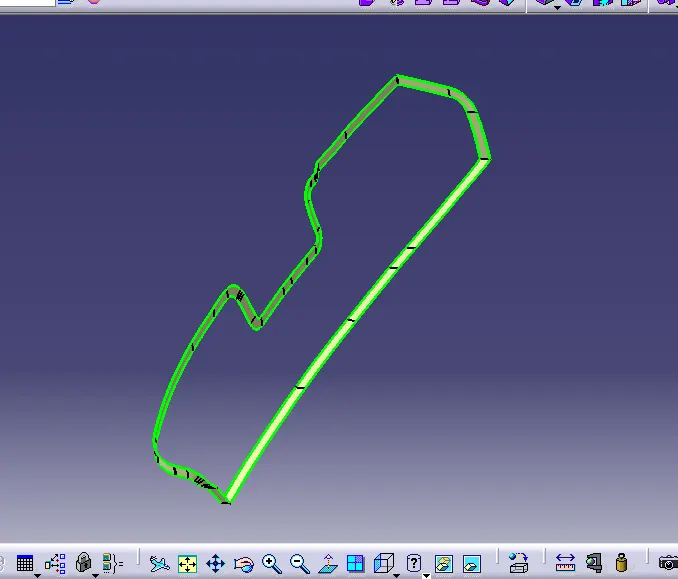
Class A and Class C (JOIN):
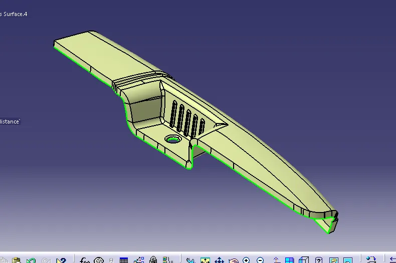
Class A, Class B and Class C together (TRIM):
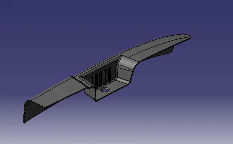
Final Door arm rest surface
- Now, Trim B surface with Joined A and C surface to get final surface.
- Then make a solid body out of it.
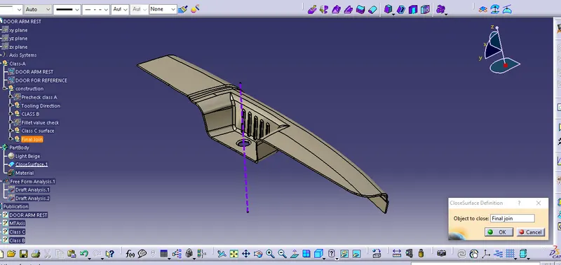
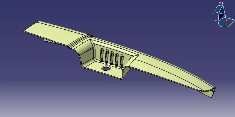
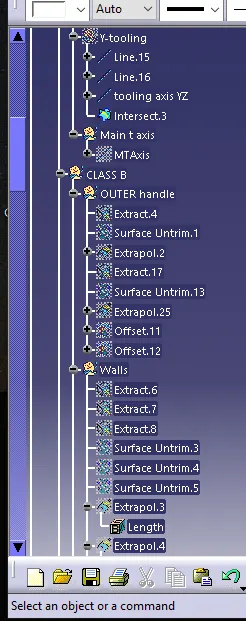
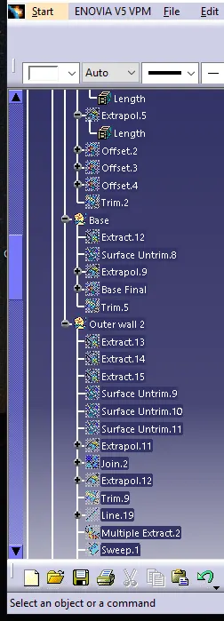
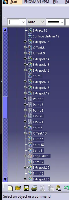
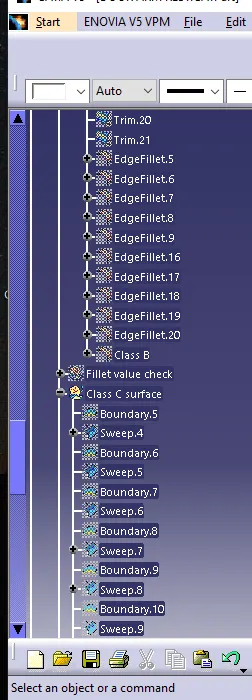
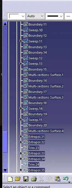
Tree structure:
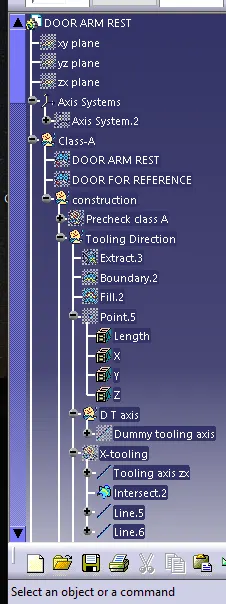
Isometric view:
Front view:
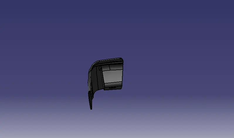
Back view
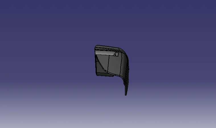
Side view:
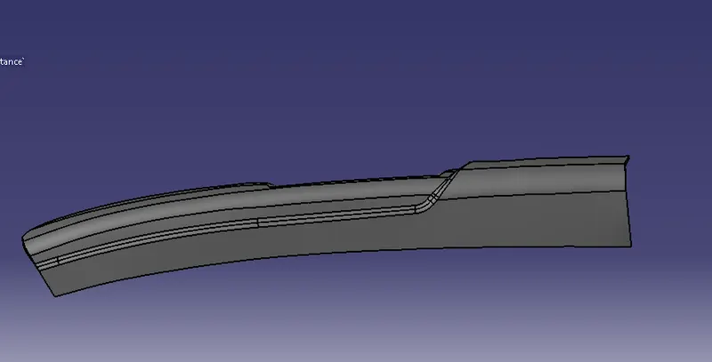
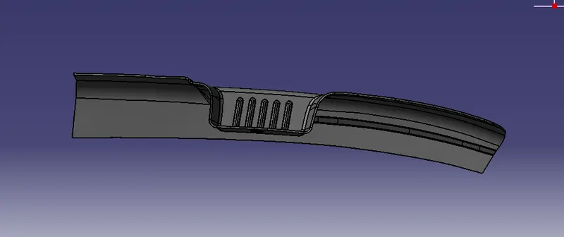
Top View: