Door Arm Rest Week 8 Challenge
Objective:
To Create the Tooling Axis,Class B,Class C and Draft Analysis of Door Arm Rest from the given CLASS A.
Procedure:
Tooling Axis:
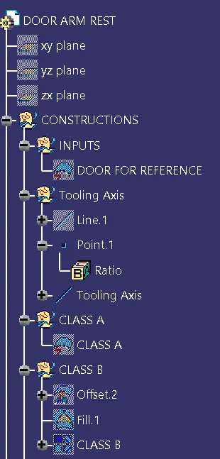
- To create the tooling axis we should identify the proper direction by checking along X,Y,Z.
- The tooling axis is drawn on the z direction.
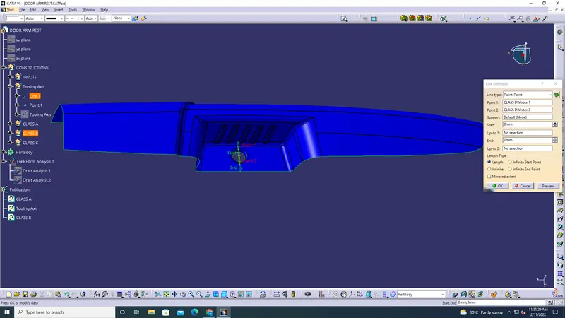
- Create a line on the location hole by selecting the 2 vertices.
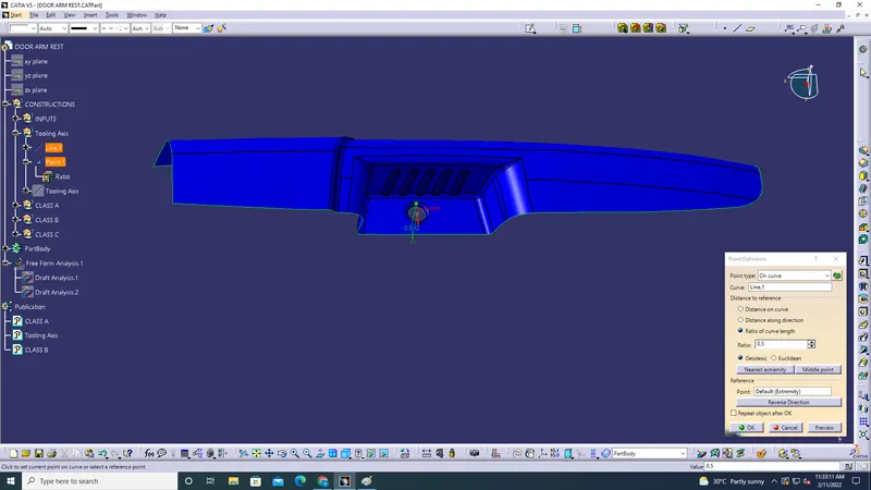
- Create a point on the line and select middle point.
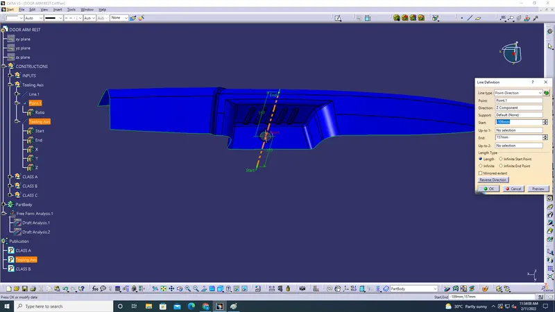
- On the created point draw a line with Point-Direction along Y axis.
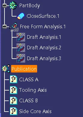
- Publish the Tooling Axis.
Line creation Between Two vertex point:
Point Creation for Tooling Axis:
Line Direction for Tooling Axis:
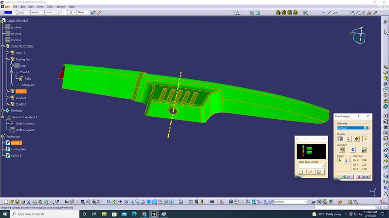
Draft Analysis On Class A with the created Tooling Axis:
CLASS B:
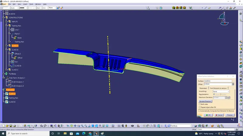
- Offset the given Class A with 2.5mm thickness.
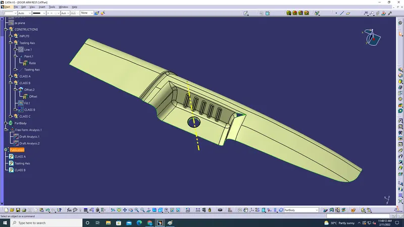
- There is a certain region which is not closed on the B surface.
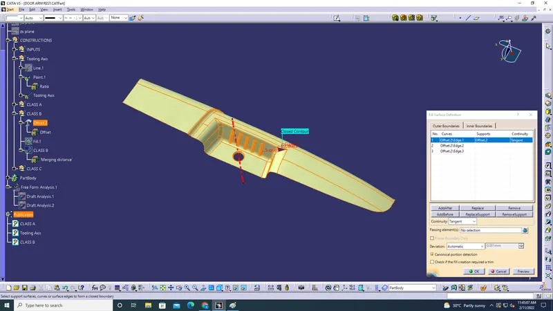
- The missing portion is filled using fill command.
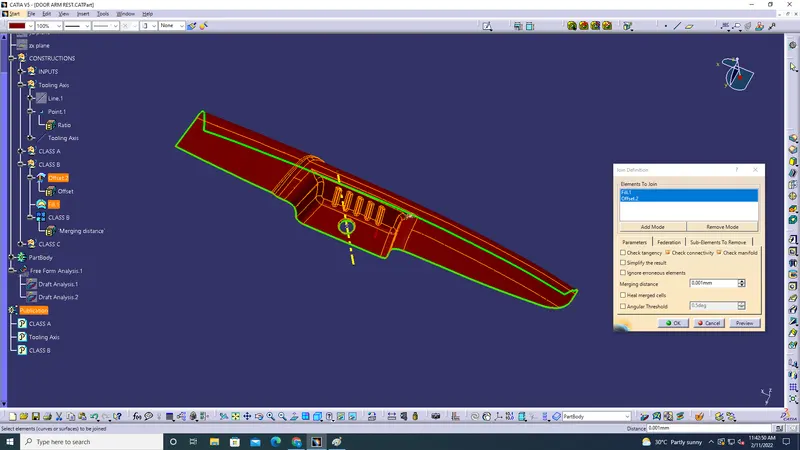
- The offset & fill region is joined using join commad. To get the fully closed Class B surface.
Offset of Class A Surface to 2.5mm to Created Class B:
Missing Portion on the Class B surface:
Fill command used on the missing Portion:
Join Command used to Join the Offset and Fill to created a fully closed Class B surface:
CLASS C:
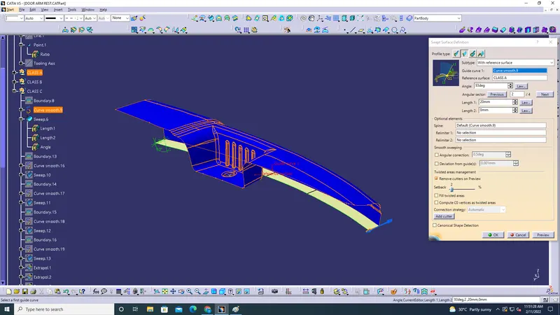
Step-1:
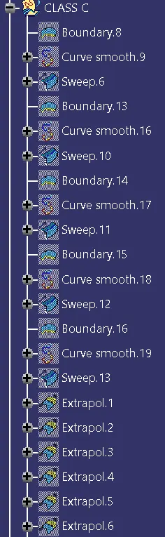
- To create the Class C surface we have to select the boundary with limit point 1 at one edge and limit point 2 at one edge.
- Smooth cure the boundary with curvature.
- Sweep the with reference surface, Guide Curve 1: Smooth Curve, Reference Surface: CLASS A, Angle: 93, Length =20mm.
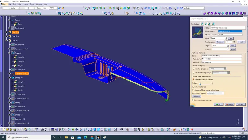
Step-2:
- To create the Class C surface we have to select the boundary with limit point 1 at one edge and limit point 2 at one edge.
- Smooth cure the boundary with curvature.
- Sweep the with reference surface, Guide Curve 1: Smooth Curve, Reference Surface: CLASS A, Angle: 93, Length =5mm.
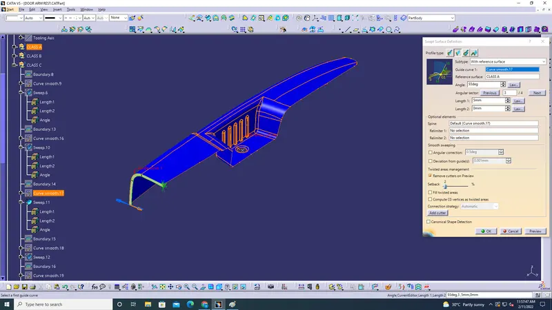
Step-3:
- To create the Class C surface we have to select the boundary with limit point 1 at one edge and limit point 2 at one edge.
- Smooth cure the boundary with curvature.
- Sweep the with reference surface, Guide Curve 1: Smooth Curve, Reference Surface: CLASS A, Angle: 93, Length =5mm.
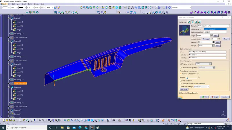
Step-4:
- To create the Class C surface we have to select the boundary with limit point 1 at one edge and limit point 2 at one edge.
- Smooth cure the boundary with curvature.
- Sweep the with reference surface, Guide Curve 1: Smooth Curve, Reference Surface: CLASS A, Angle: 93, Length =5mm.
Step-5:
- To create the Class C surface we have to select the boundary with limit point 1 at one edge and limit point 2 at one edge.
- Smooth cure the boundary with curvature.
- Sweep the with reference surface, Guide Curve 1: Smooth Curve, Reference Surface: CLASS A, Angle: 93, Length =5mm.
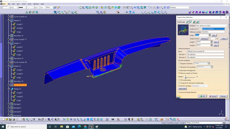
Step-6:
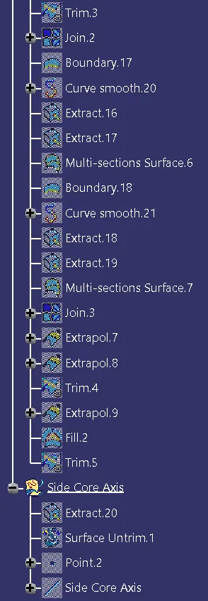
- Extrapole the regions which is not intresecting with each other.
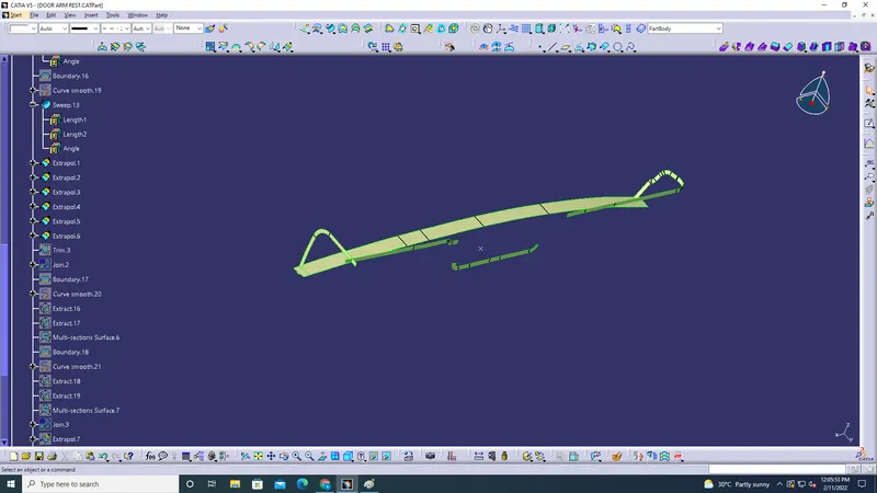
Step-7:
- Trim the extra region after extrapole.
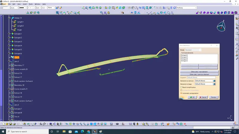
Step-8:
- Join the Class A+TRIM 3+Sweep
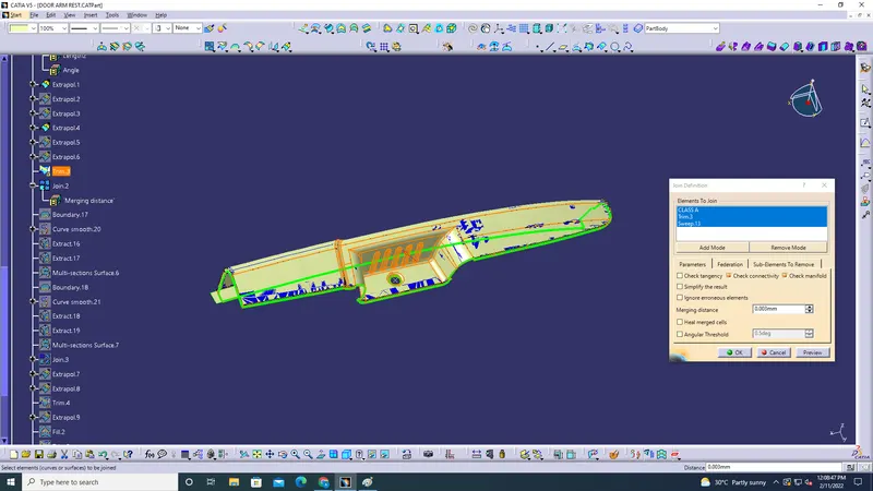
Step-9:
- Extract the missing regions.
- By using Multi Section command create the missing part.
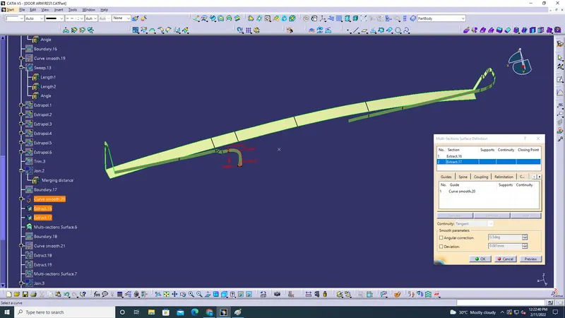
Step-10:
- Extract the missing regions.
- By using Multi Section command create the missing part.
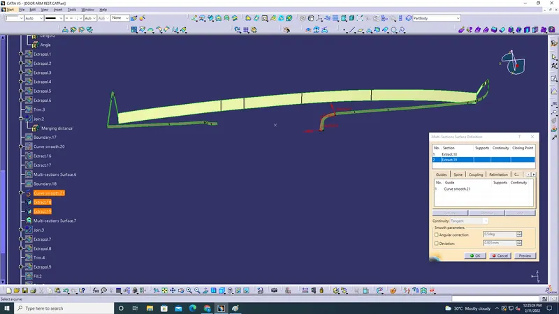
Step-11:
- Join all the parts to create the complete Class A + Class C
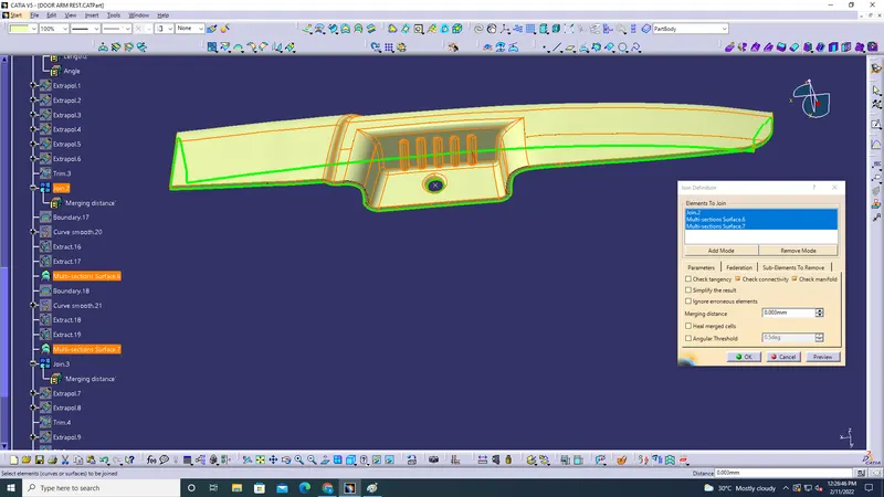
Step-11:
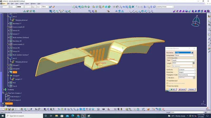
- EXTRAPOLE the Class B to a length of 3mm amd Trim the Join & Extrapole regions.
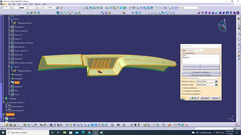
Step-12:
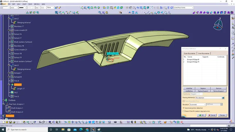
- Extrapole the regions which is not closing.
- Use Fill command to close the region.
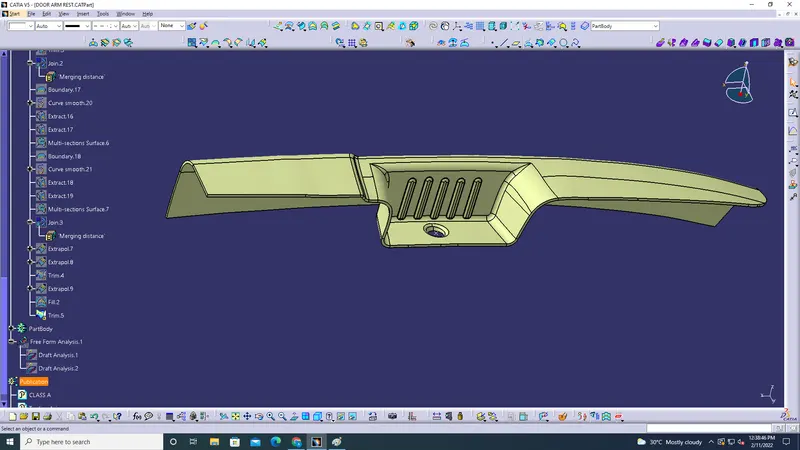
- Trim the Fill and the Extrapole to get the Class A+Class B+Class C surface.
Step-13:
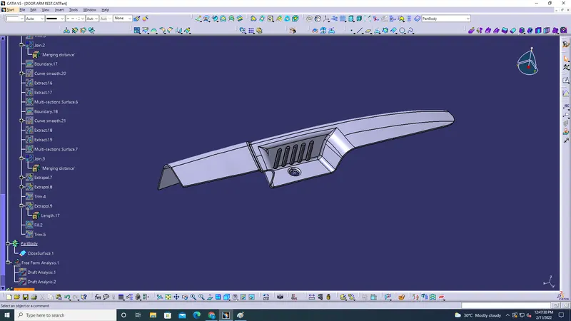
- Convert the body into a Solid Part by defining in Part Body.
- By switching to Part Work bench use Closed surface to create into a solid part.
Draft Analysis on the Side Core Axis:
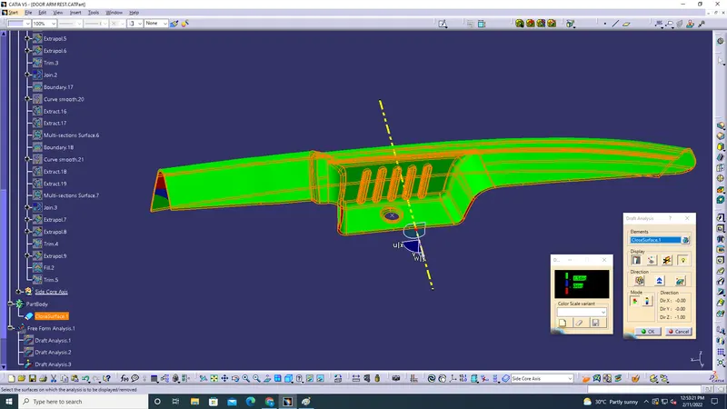
Draft Analysis on the Tooling Axis:
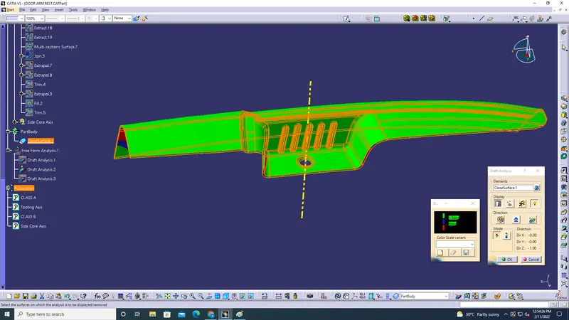
Tree Structure: