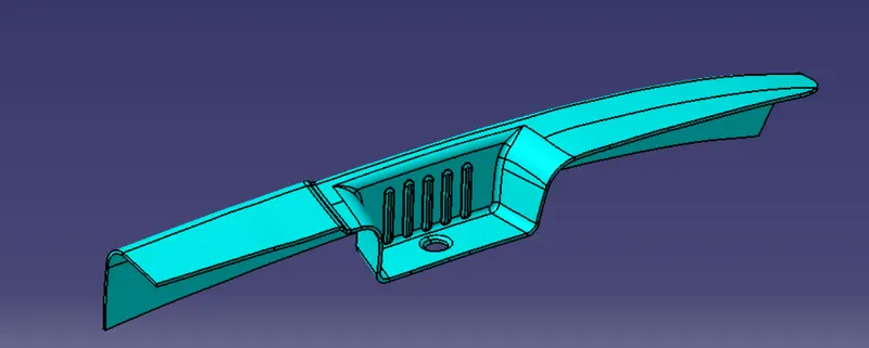
Door Arm Rest Week 8 Challenge
AIM:
Creation of Door Arm rest and add thickness to it.
OBJECTIVES:
- Create Class B and C surfaces through Class A surface.
- Create tooling axis using bisecting method.
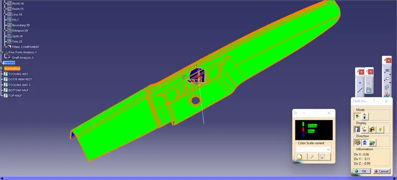
- Perform draft analysis.
PROCEDURE:
The procedure is divided into two parts first creating the tooling axis then performing the draft analysis.
Creating tooling axis using bisecting method:
- The first thing to do is finding out the possible tooling direction by visually checking the part. Rotate the part in all direction and find out most suitable direction for tooling. Here in this case viewing from Z direction we can clear the face in tooling.
- Then we create a point on the surface of the part, we can create the point anywhere on the surface but usually we take CG point or take a point near to centre. On this point we put a new axis system.
- Then we are finding out the tooling axis in X direction. For that intersect command is used to get the boundary in X direction or XZ plane.
- Extending the drafted face using a point to point line command. Then using bisecting line command bisect both extended line to get tooling axis in X direction.
- Since in Y direction there is no wall to create bisect. We finalise the tooling axis in X direction as main tooling axis.
Performing the draft analysis:
- Open Feature draft analysis option from Insert > Analysis > Feature draft analysis.
- A new window pops up by default it will be in quick analysis mode. Change the range to 2.9deg.
- Next you have to position the compass on the tooling axis by dragging the compass from top right corner of the working area. The W axis of the compass should be inline with the axis.
- Then you have to define the compass by click on compass icon on the draft analysis window. Then lock the positon of the compass by clicking the lock icon.
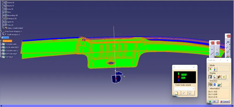
- After that select the surface and the whole surface will shows a color range. For a good draft make the surface fully green.
Creating Class B and Class C surface:
- For creating Class B surface we have to extract each faces from Class A surface and untrim those faces and offset them to 2.5mm.
- If needed extrapolate the surfaces and trim the unwanted portion.
- Give the fillets accordingly.
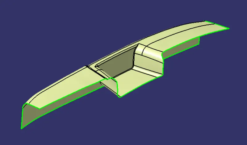
FIG: Class B surface
- For creating Class C surface we have to create the boundary for Class A surface and sweep the boundary with a 3deg draft.
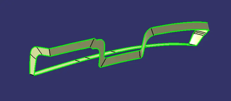
FIG: Class C surface
- Join Class A surface with Class B surface and trim it off with Class B surface.
RESULT:
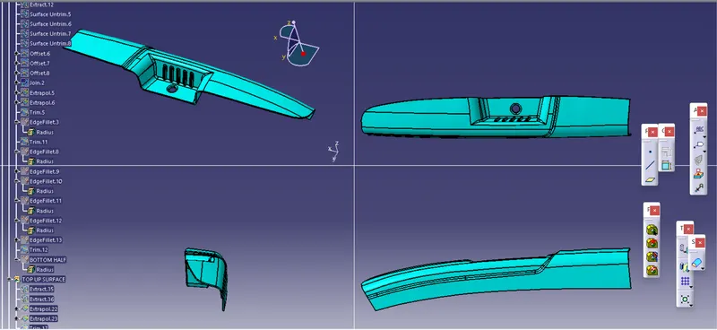
TREE STRUCTURE:
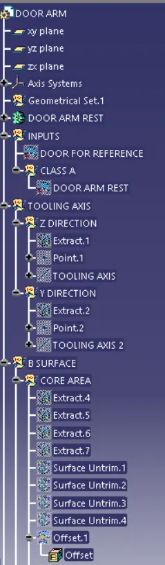
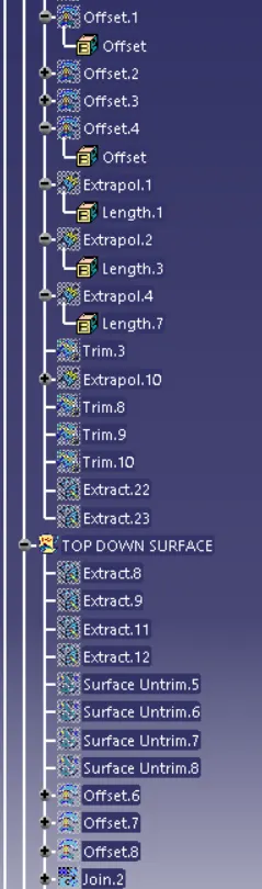
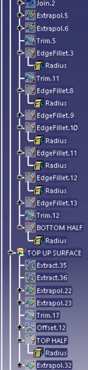
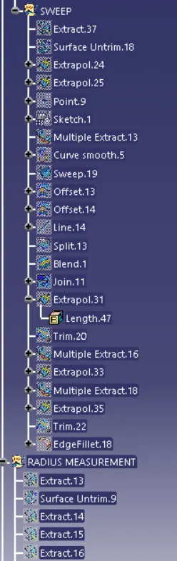
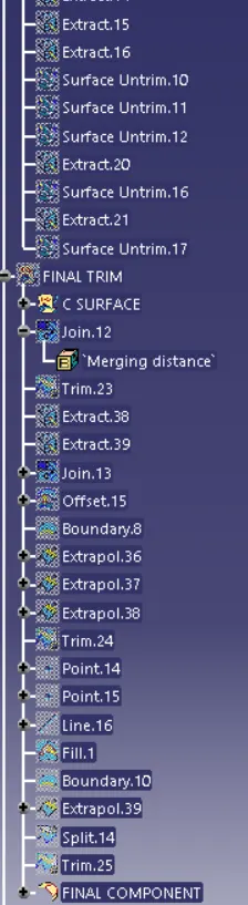
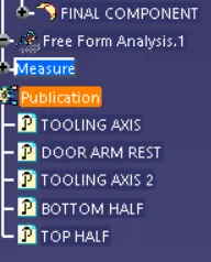
DRAFT ANALYSIS:
DRAFT ANALYSIS FOR SIDE CORE:
FINAL SOLID BODY: