Door Arm Rest Week 8 Challenge
DOOR ARM REST DESIGN
OBJECTIVE
To create B surface of door amr rest
To create C surface
To develop the tooling axis for the plastic component
To perform drafting analysis
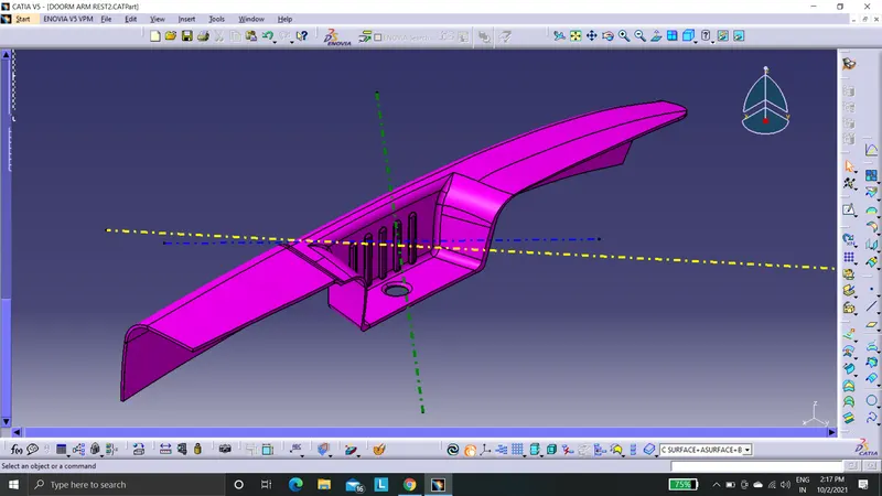
CLASS- A SURAFCE
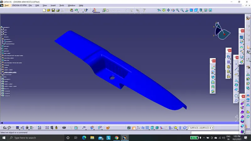
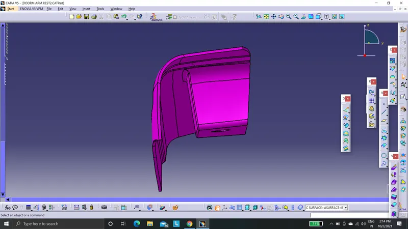
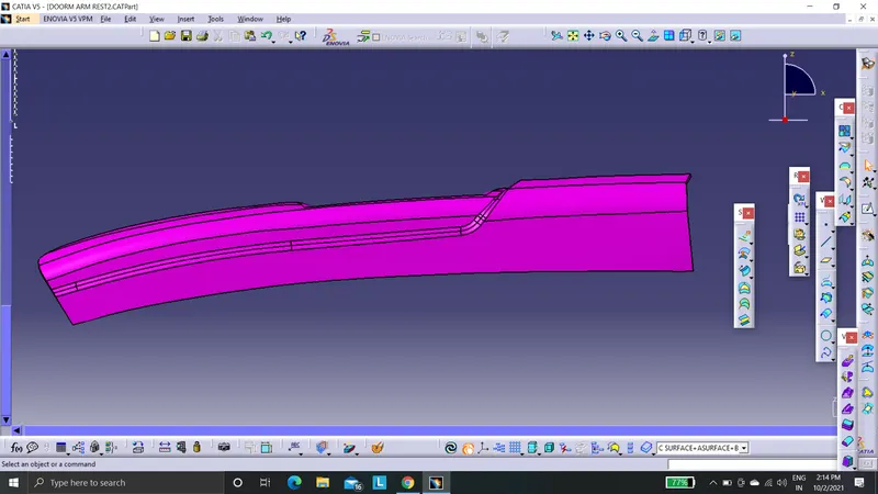
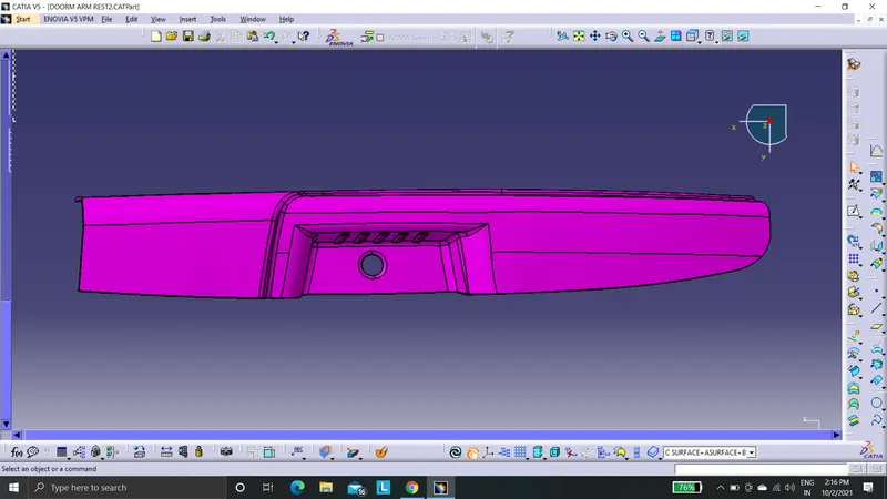
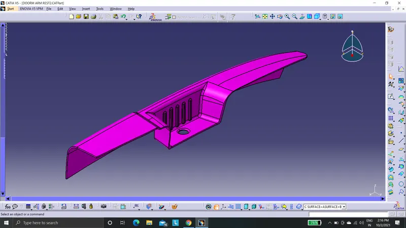
This is the given class- A surface. In which we have different features to consider.
GENERATING TOOLING AXIS
1. Do the boundary check do for class A. Through which we can ensure whether the class A completely closed or not. This is the basic design check we need to do.
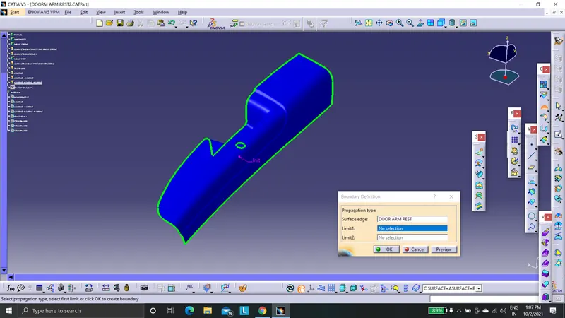
2. Since this part has features in all three directions, we need to clear all directions using tooling axis for manufacturing this component.
TOOLING DIRECTION ALONG Z- AXIS
In which the tooling direction along Z axis is created and then checked using draft analysis.
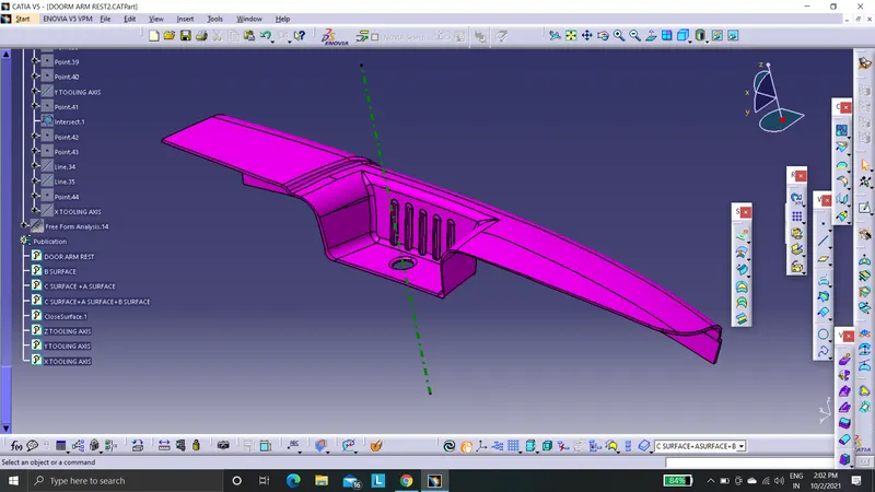
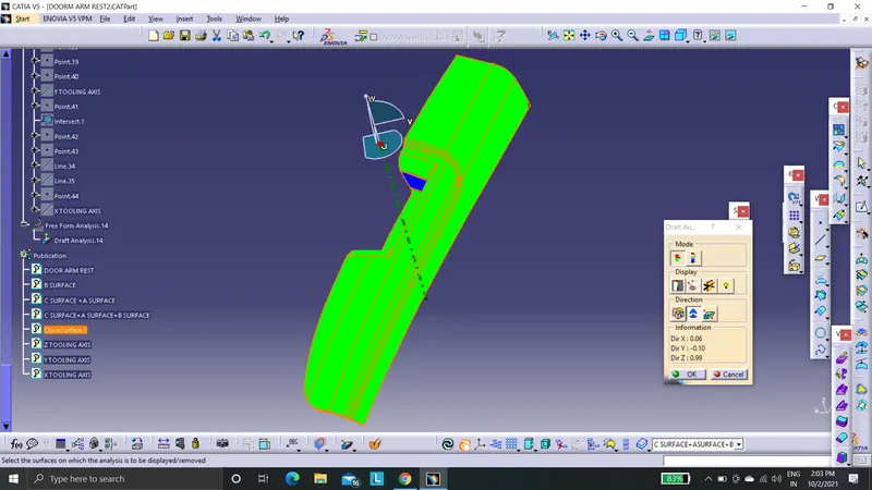
This shows that the tooling direction clearing all faces in Z direction. But some features in Y and X directions are still in negative draft with respect to the Z direction, there are some undercuts which are not desirable. Therefore we need to provide individual slider for those undercut directions
TOOLING DIRECTION ALONG Y DIRECTION
In which the tooling direction along Y axis is created and then checked using draft analysis.
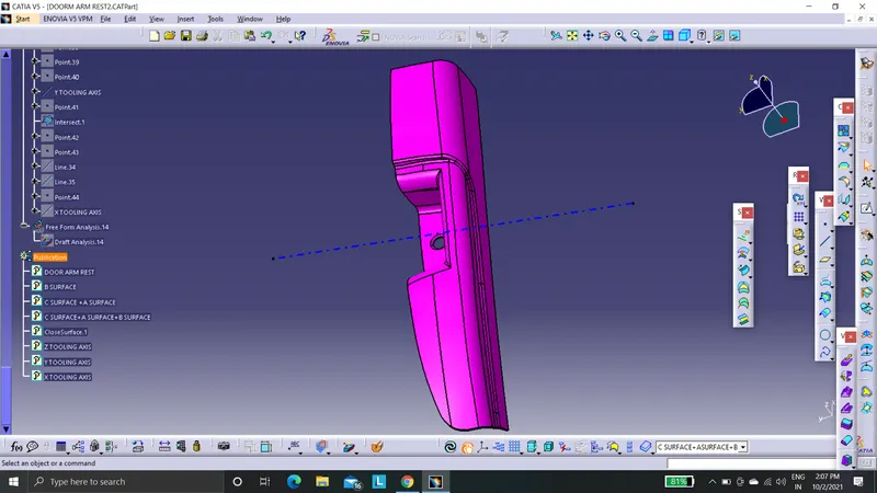
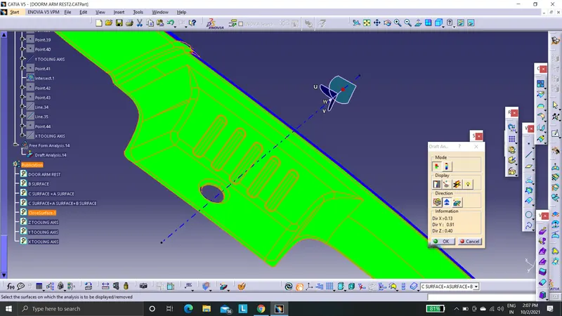
This shows that the tooling direction clearing all faces in Y direction. We have already cleared Z direction features. But in X direction there are some under cuts it needed to be cleared.
TOOLING DIRECTION ALONG Z DIRECTION
In which the tooling direction along X axis is created and then checked using draft analysis.
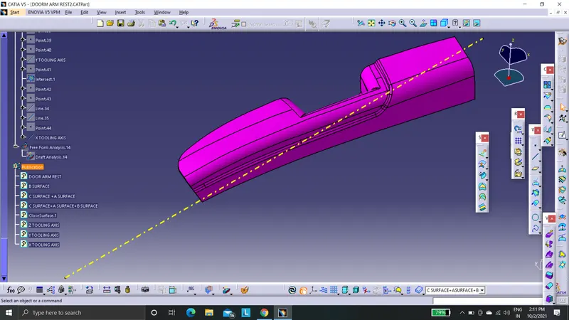
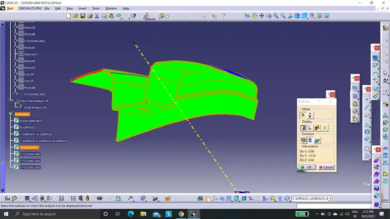
This shows that the tooling direction clearing all faces in X direction. We have already cleared Z and Y direction features.
DOOR ARM REST DESIGN PROCEDURE
CLASS-B SURFACE
WALL CREATION
- Bringing in the class-A surface.
- Extracting the four wall surface.
- Un-trim the extracted surfaces.
- Extrapolate the un-trimmed surfaces.
- Trim the surface as per required shape.
- Offset the created rib surfaces for 2.5mm. ( CLASS-B SURFACE)
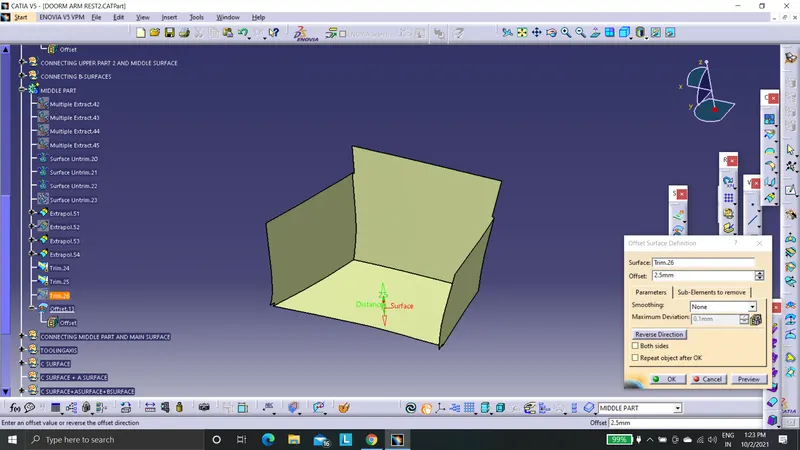
CREATION OF BASE SURFACE 1
- Extract the base surface from class-A surface.
- Un-trim the base surface.
- Extrapolate the base surface.
- Offset the base surface for 2.5mm
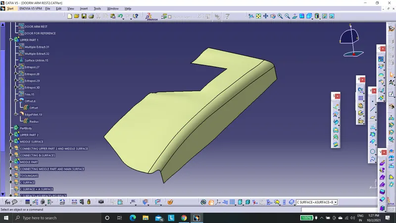
CREATION OF BASE SURFACE 2
- Extract the base surface from class-A surface.
- Un-trim the base surface.
- Extrapolate the base surface.
- Offset the base surface for 2.5mm
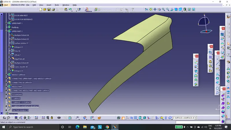
CREATION OF SURFACE CONNECTING BASE 1 AND 2
- Extract the sweep profile
- Sketch the line tangent to the extracted sweep profile
- Extract rhe guide curve
- Use sweep command
- Offset for 2.5mm
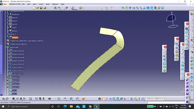
JOIN
- Trim the surfaces to form a single surafce
- This is th class B-surface
- Apply fillets by subtracting 2.5mm from th actual value of class A surface
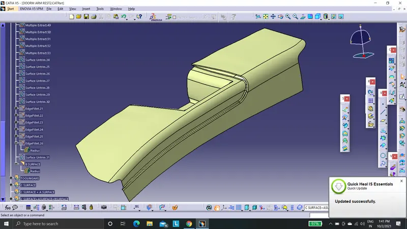
CLASS-C SURFACE
This the connecting surface of class-A and class-B surfaces.
- Extract the boundary curves from class A surface
- Smoothen the boundary curve generated because it is already noted that the boundary curve is discontinuous.
- Use sweep command to generate class-C surface along the draft direction with 3 degrees drafting angle with respect to the tooling axis.
- Trim the discontinuous surfaces, create those surfaces using multi section sweep
- Join class C surface and class A surface
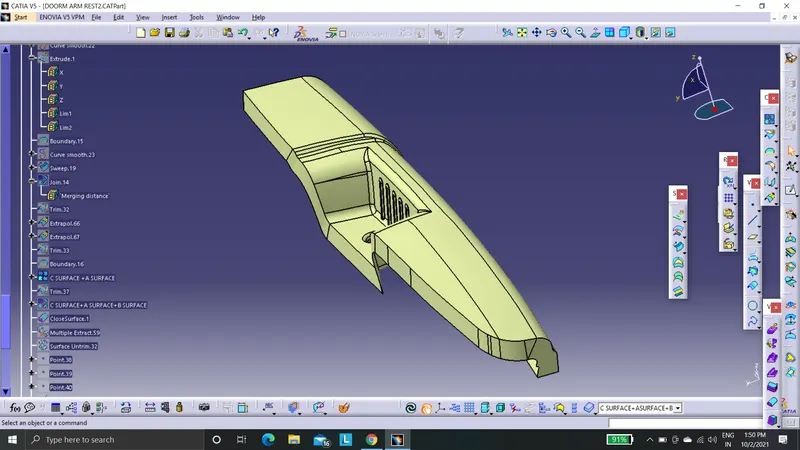
JOIN ALL SURFACES
Join all the surfaces (A+B+C) using join command.
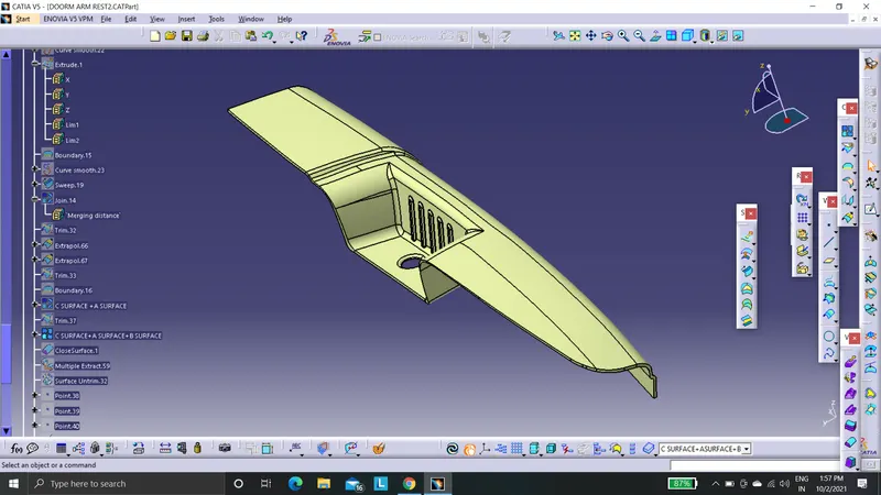
CLOSED SURFACE
- Publish class-A, class-B, class-C surfaces and tooling axis.
- Join all the surface together.
- Create closed surface.
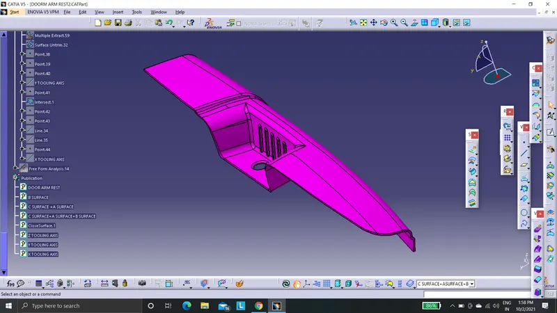
FRONT VIEW
SIDE VIEW
TOP VIEW
ISOMETRIC VIEW
DRAFT ANALYSIS
All toolind directions
ALONG Z
ALONG Y
slider direction
ALONG X
slider direction
CONCLUSION
Hence the part is created and then the draft analysis is done.