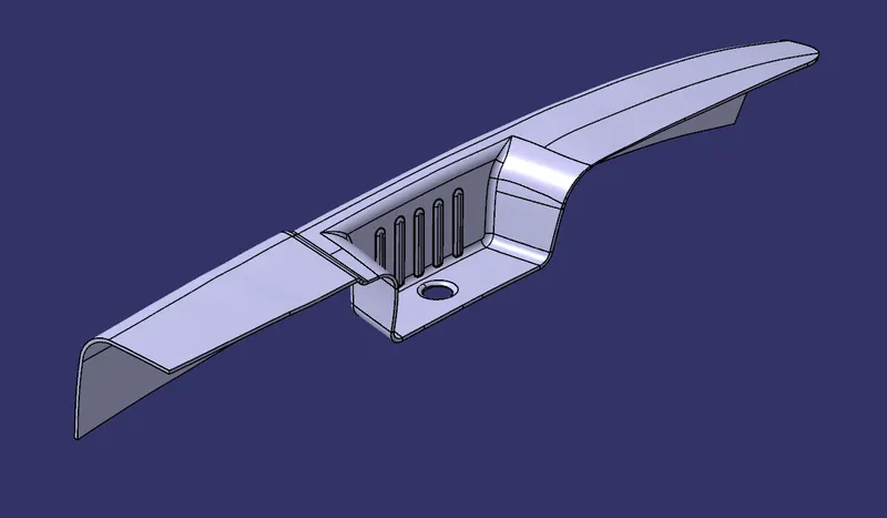
Door Arm Rest Design
DOOR ARM REST DESIGN
CREATING MAIN TOOLING AXIS:
- For obtaining the main tooling direction, we will consider all the 3 axes and view the part along them.
- We extract the bottom hole edge, use fill surface to fill the hole and take a point at its center.
- After viewing the part in different views, we can conclude that direction along Z axis is appropriate for our tooling axis.
- For that we will consider tooling clearing along both X axis and Y axis.
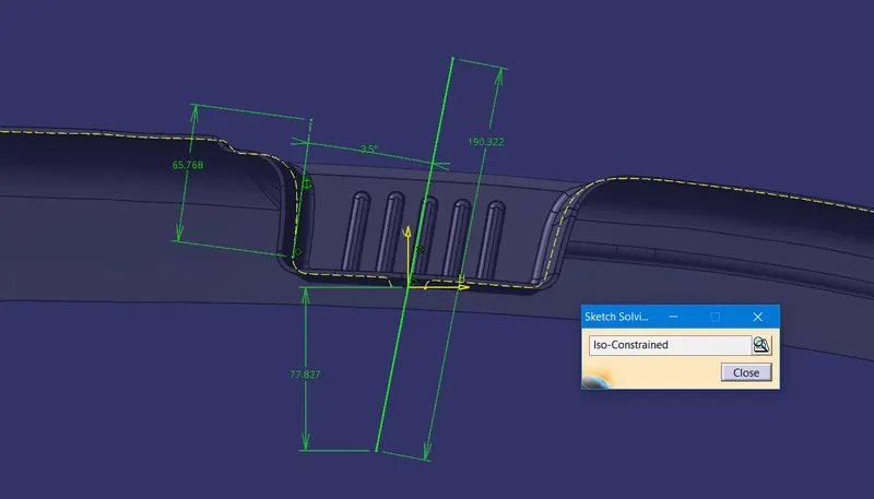
- For Y direction tooling clearing, as shown below, we sketch and take intersection of the body along a plane created parallel to XZ plane. Take a line as shown below and later on adjust the angle with the line on left by trial-and-error method. As the vertical line on right can be easily cleared, no need to consider that. Thus, we get the Y direction tooling clearing axis.
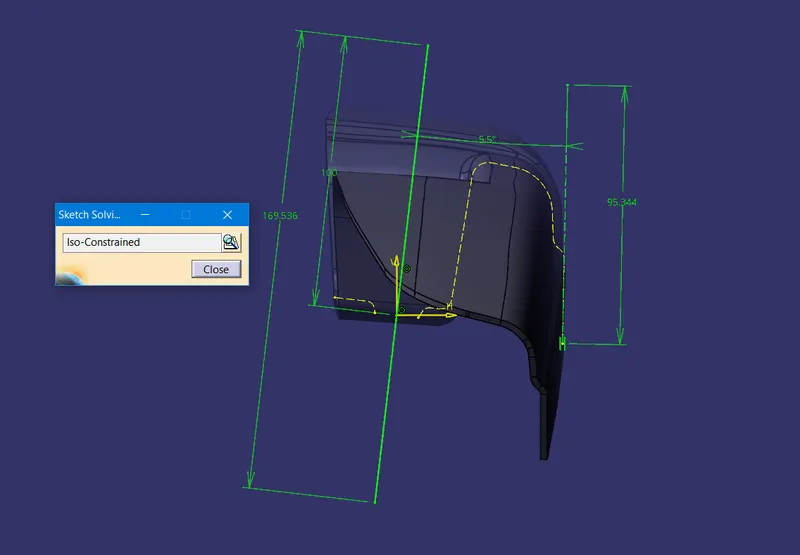
- Similarly, for X direction, we take sketch along a plane created at the point and parallel to YZ plane and draw the sketch as shown below and take a line as shown in the sketch. Adjust the angle of line with respect to the vertically inclined construction geometry line on the right by trial and error, until you get tooling cleared along X direction.
- Now extrude both the lines along X and Y directions respectively such that they will intersect as shown below.
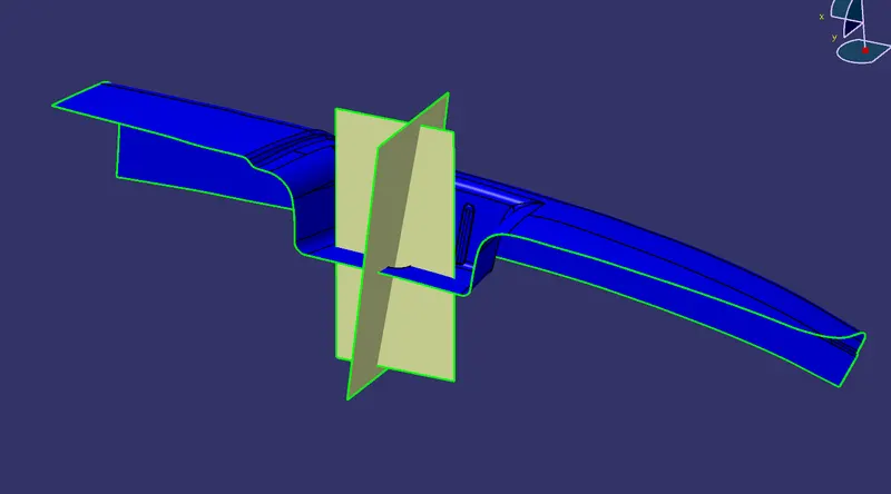
- Now, using intersection feature, take a line formed by intersection by previously formed 2 surfaces as shown below. This is our main tooling axis.
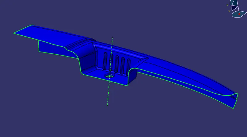
CREATING SIDE CORE TOOLING AXIS:
- As some part is not getting completely cleared in main tooling direction, we will introduce a side core and find the appropriate tooling direction for the same.
- For side core tooling axis direction, extract the surface shown (highlighted) below.
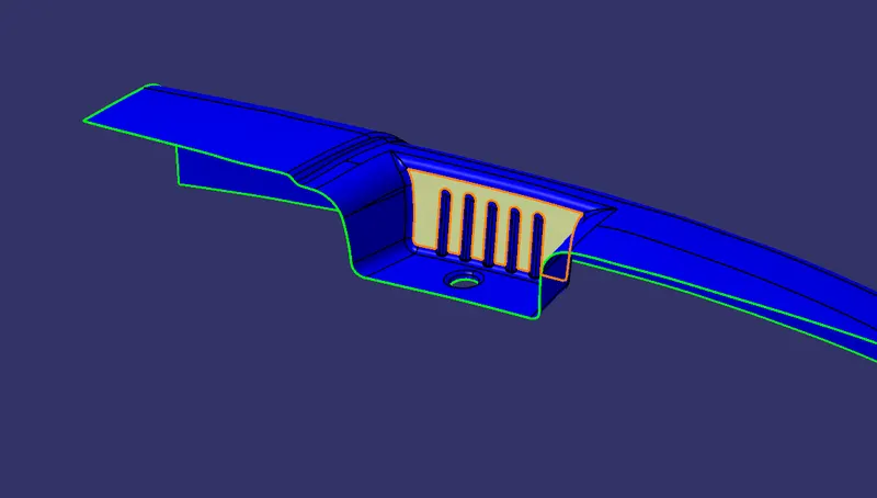
- Now take a point some where on the surface and take a line along through that point and along Y axis as below.
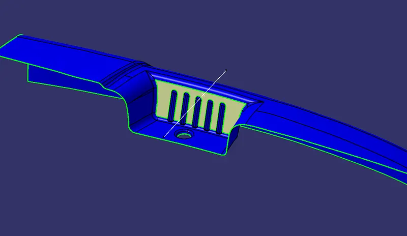
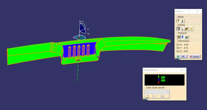
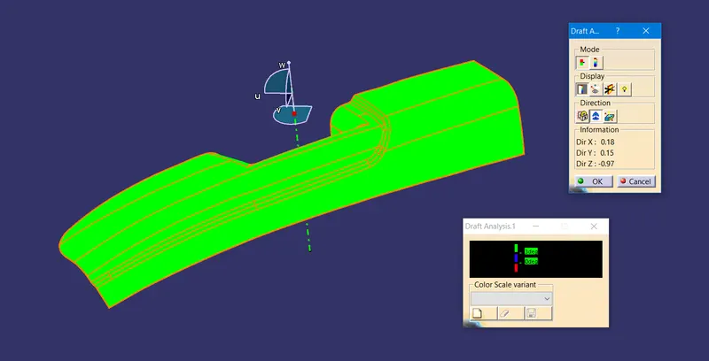
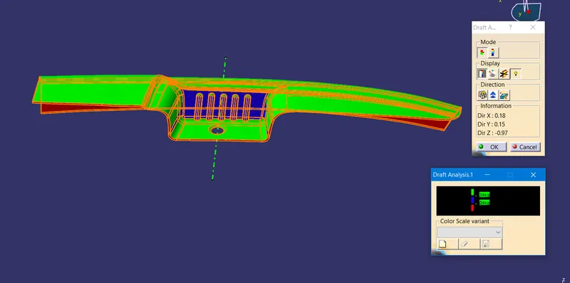
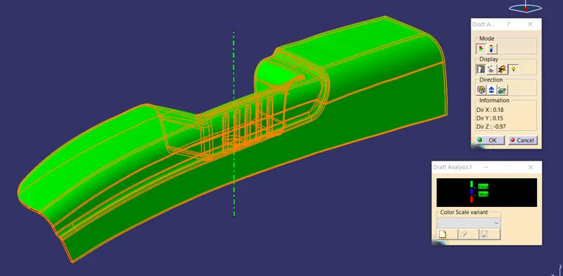
- Now, in draft analysis, take the direction along this line first, and then adjust the compass until you get the required portion cleared.
- Then take a line along that compass direction. Thus, you get the side core tooling axis.
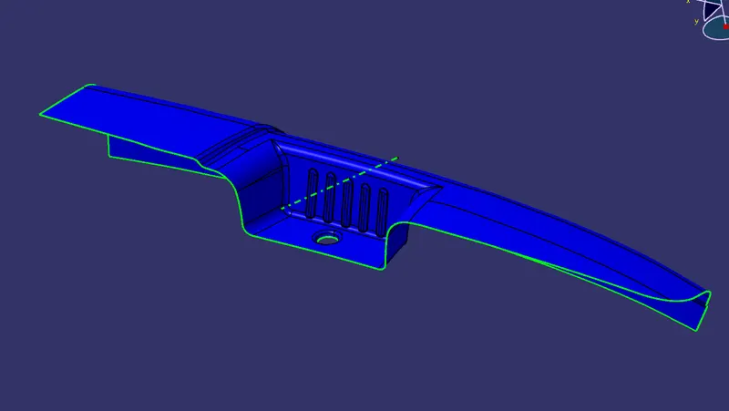
IMAGES
DRAFT ANALYSIS AND COLOR SCALE VARIANT
- MAIN TOOLING AXIS
Class A Surface
View1
View2
Solid Body
View1
View2
- SIDE CORE TOOLING AXIS
Class A Surface
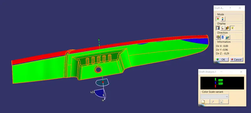
Solid Body
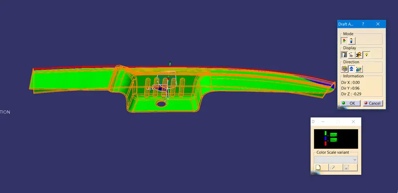
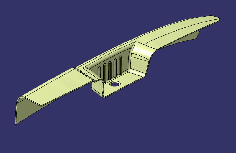
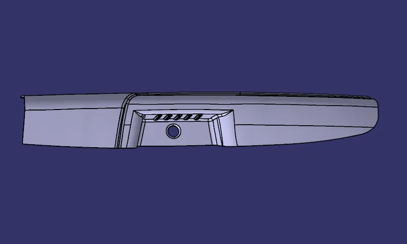
Model different views
Surface Body
Front view
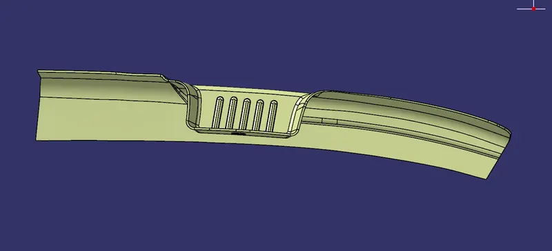
Side view
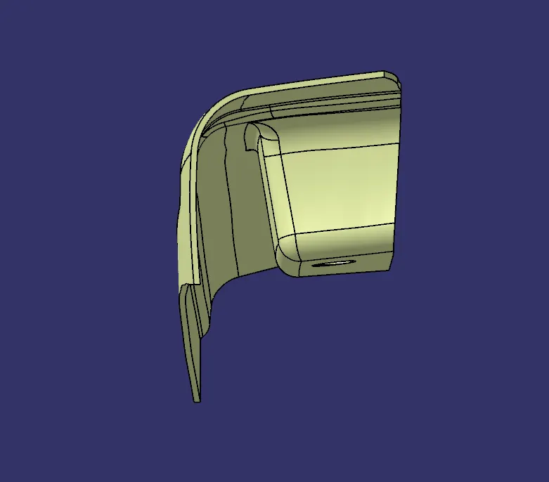
Top view
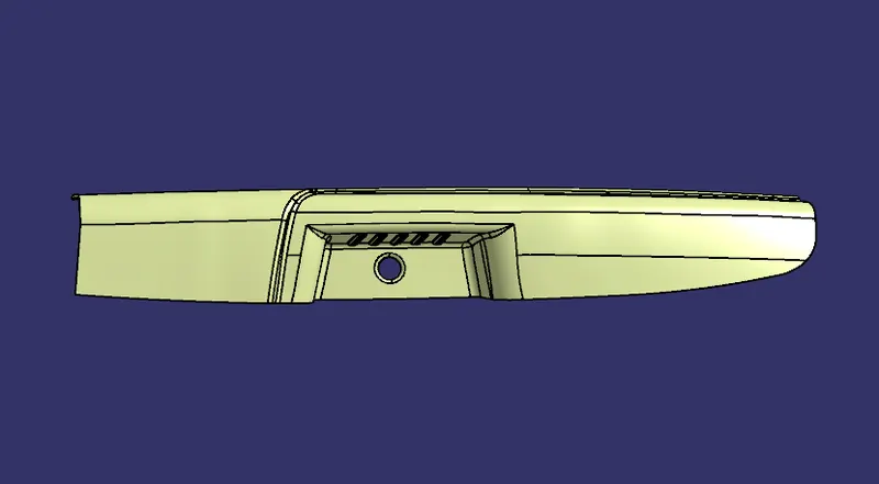
Isometric view
Solid Body
Front view
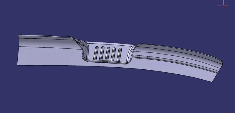
Side view
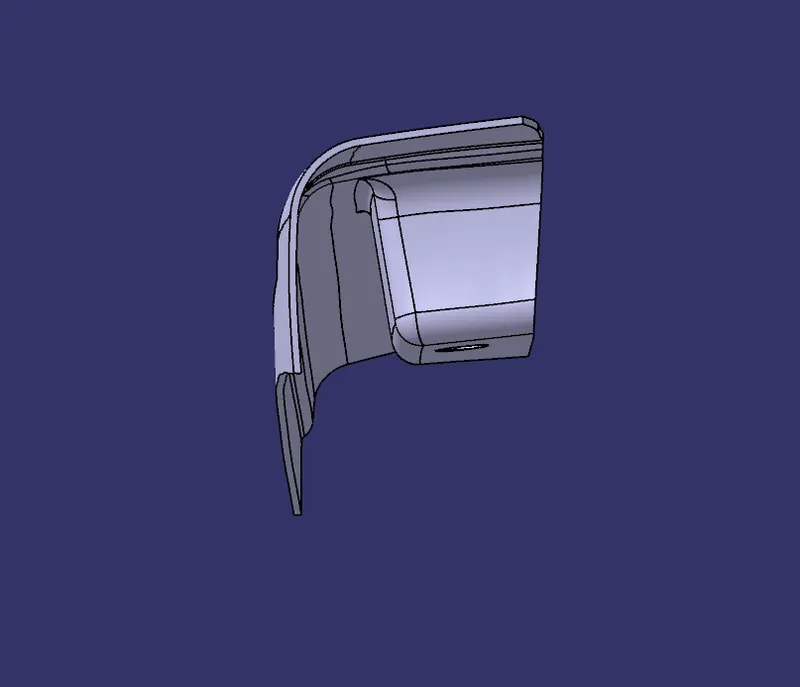
Top view
Isometric view