Door Arm Rest Week 8 Challenge
DOOR ARM REST BEZEL
AIM:
- To create the door arm rest plastic component through the given Class A surface and at the end performing the draft analysis on the model.
OBJECTIVES:
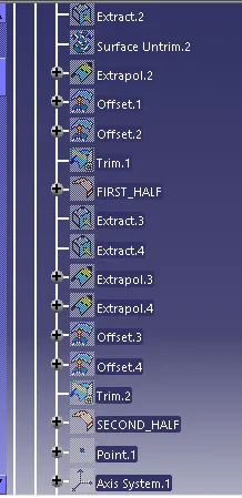
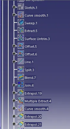
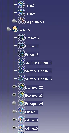
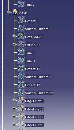
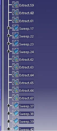
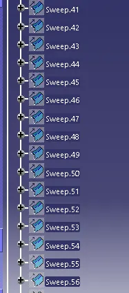
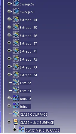
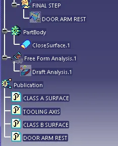
- To ensure proper tree structure is followed.
- Geometrical sets should have a proper name based on the sketches present inside of it.
- All the sketches should be created under the geometrical set.
- Use of the close surface feature to make a solid body from the surface.
- To publish the tooling axis, class A, B and C surface.
PROCEDURE:
- First import the class A surface of door arm rest model in Catia v5.
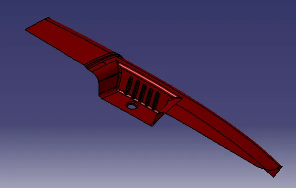
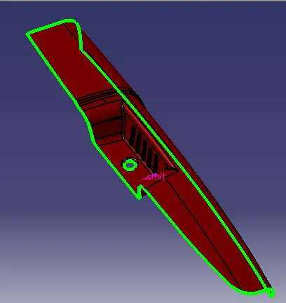
- Check the connectivity of Class A surface using boundary option. Ensure that there is no gap between the two surfaces.
TOOLING AXIS:
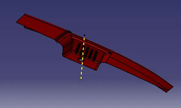
- The tooling direction is used to find the direction in which the part is ejected out of the mold. The draft on the part should be positive in order to manufature the part easily. The draft angle should be positive with respect to the tooling direction.
- To create the tooling axis, we need the proper orientation or view that gives the correct features and draft available in the component.
- So here the component view from the Z direction gives the proper view for the tool to see the features present in the geometry.
CLASS B SURFACE:
- The input of the product designer is in the form of the A-class surface. The job of the product designer is to create the B and C surface keeping all the aspects for the mold.
Class A is
1. Visible surface and aesthetic look
2. surface with textures
3. Surface provided by customer (OEM)
4. Don't have any features like (rib, bosses, etc.) on class A surface.
5. Class A surface is made from scanned data with different software like alias etc.
6. Surface which are having CURVATURE CONTINUITY is called Class A.
Class B Surface:
1. Invisible surfaces.
2. Surfcae needs to be created according to the class A surface.
4. Having all features (Rib, boss, snap etc.) in B side surface only.
5. Surface which is having TANGENT CONTINUITY is called Class B.
The process for the B class is as follows:
- First, extract all the surfaces for the inclined portion of the base plate.
- Then these surface are first untrimmed to get the intersection for surfaces so that a replica can be created.
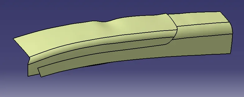
- If the surface are not intersected, then extrapolate by point continuity propagation is used to make these surface have an intersection between them.
- Lastly, the surface trim is used to get the replica for the inclined surface.
- Now, the thickness of the final component is 2.5mm so this obtained surface is offset below by 2.5mm.
- Like that the rest of the region is extracted and trimmed to get the final B surface.
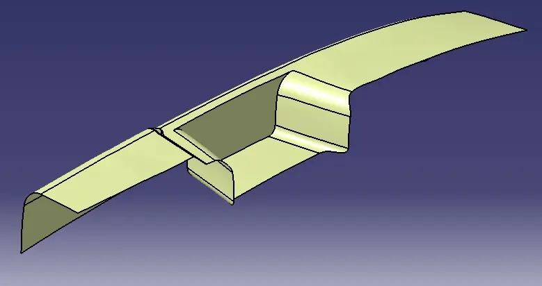
- Now, the fillets assigned in the B class surface will be 17-2.5mm = 14.5mm. This is to have the uniform thickness between the A and B classes.
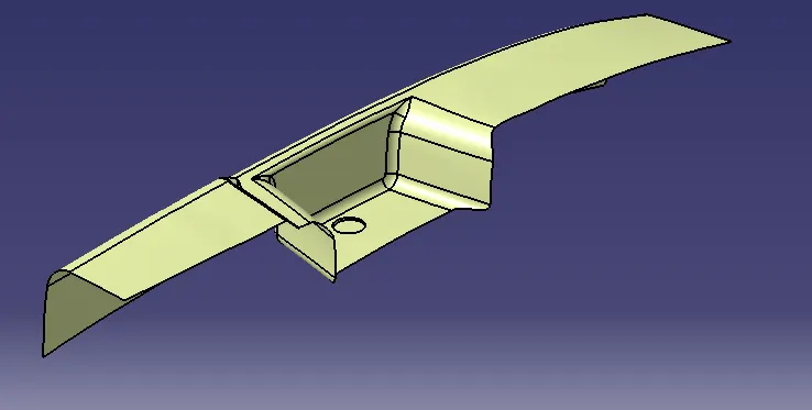
- The whole component B surface is created in small parts, then joined using the trimmed option and then the final fillets are assigned.
C SURFACE:
- C Class is where the thickness of the component can be seen.
- The process for C Class surface is as follows:
- The C class surface will be created using the sweep command and for that, the boundary lines are obtained from the A class surface.
- The curve part is then smooth by some value for ease in sweeping.
- Then, all boundary lines are sweep with draft direction since all surfaces must have a draft angle of 3 degrees. Also, the tooling axis is used as the direction of the sweep.
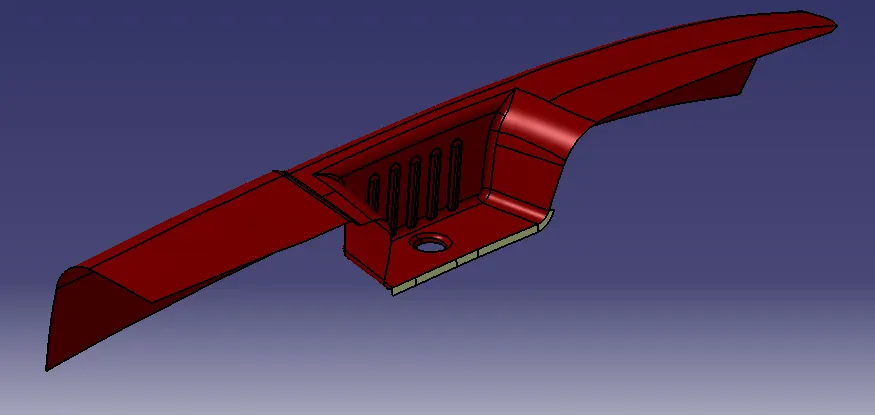
- Next, the surface are joined with the A class to form a complete A and C surface.(note merging distance is kept at 0.003mm to avoid any gaps).
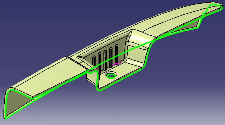
- Lastly, the A and C is trimmed with the B surface to get the final baseplate component. This obtained surface is then thickened in part design.
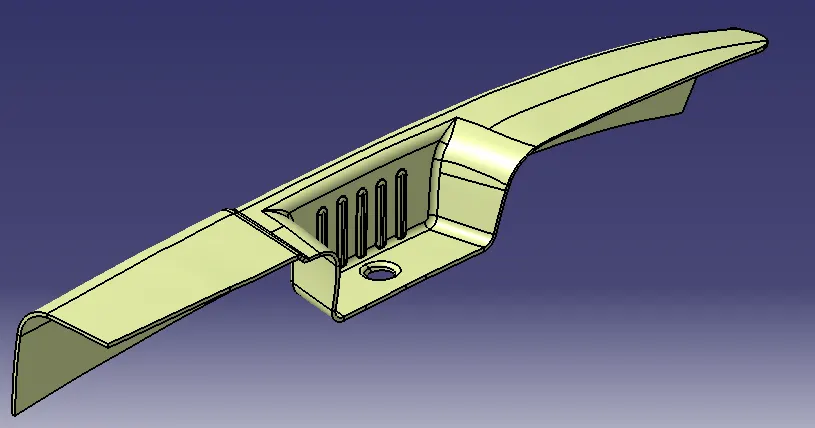
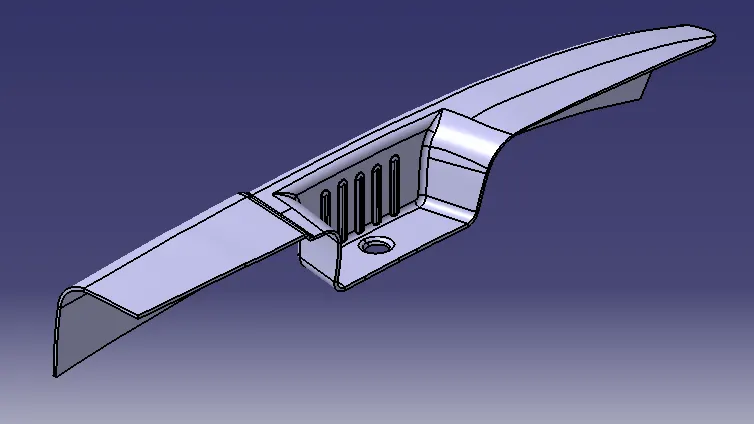
DRAFT ANALYSIS:
- To perform the draft analysis the view parameters are first set to material mode.
- Then go to Insert >> analysis >> feature draft analysis.
- First, select the axis system and drag the axis system to align and coincide with the tooling axis and lock the orientation. This axis system defines the draft direction according to the tooling axis.
- Switch on the color scale and set the minimum draft value. Here it is set to 3 degrees and it will be displayed in green color. any draft angle below 3 degrees will be shown in red color.
- Here, the compass sirection is rotated to have the positive direction in the maximum portion of the part. Then the compass is locked in the orientation and a new tooling axis is created using the compass as the direction.
- Now select the running point tool to measure the draft angle at the various locations and then if all surfaces pass the draft analysis switch on the light effect that will show the component in green color if the component has the required draft angle.
- The bin portion of the arm rest has a negative draft because the model is not accurate and has some inappropriate surface that creates the problem in the final drafting. To overcome this problem, we clear this region properly in ejection.
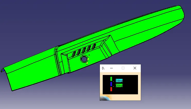
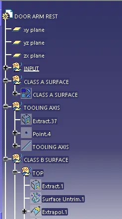
- To publish the tooling axis and class A, Class B, And Class C surfaces first select them and then Go to menu bar > Tools > Publication. This will publish the tooling axis and class A, Class B and class C surface which will be available in the Tree Structure.
TREE STRUCTURE:
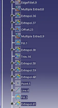
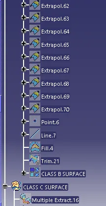
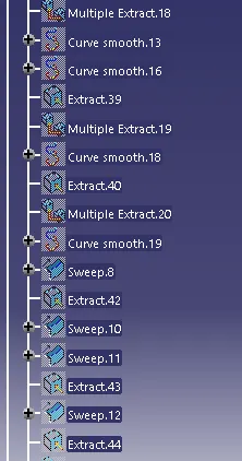
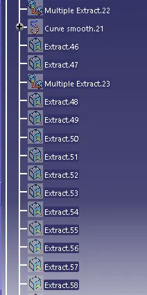
VIEWS:
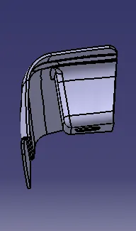
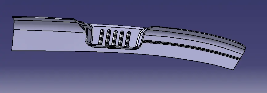
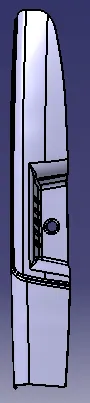
CONCLUSION:
- Door Arm Rest plastic component using Class A surface have been successfully created and draft analysis have also been performed for the same.