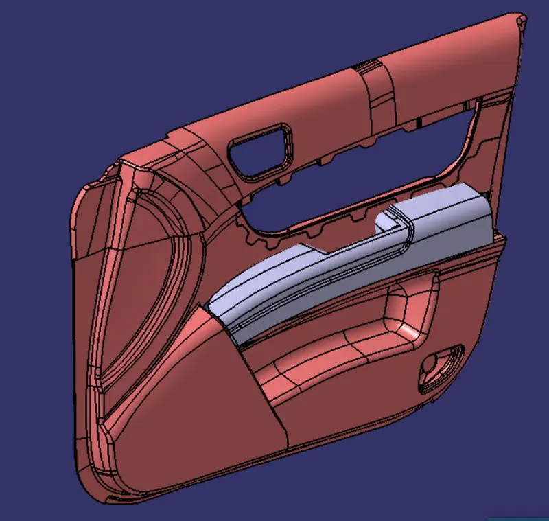
Door Arm Rest Week 8 Challenge
DOOR ARM REST
INTRODUCTION
Tooling axis is the direction in which the mould opens or the core cavity opens. By providing tooling axis to the component we can also do the draft analysis of the component. Draft analysis is performed on components where the ejection of materials happen after the material is made inside the tools.
Class B surfaces are the secondary surfaces that you can see sometimes, but are less important.
Class C surface are the surfaces which connects the class A and Class B surfaces.
OBJECTIVE
To create the Door arm rest plastic component through the given Class-A surface. To begin with, the tooling axis for the given Class-A Surface should be created meeting the requirements of the draft angle and at the end perform the Draft analysis on the model.
To also create the class B and class C surface of the component.
METHODOLOGY
Skin data would be provided to us by the styling team to us.
The first step is to check the continuity of the class A surface. This is to ensure that there is no gap between surfaces. If we find any then we should fix that first.
The second step is to find the tooling axis of the component.
Then we can make the component by creating the class B and class C component.
After that we can do the draft analysis of the component.
DESCRIPTION
Class A surface-
Class A surfaces is a term used in most in automotive design to describe a set of freeform surfaces of high efficiency and quality.
Class B surface-
Class B surfaces are the secondary surfaces that you can see sometimes, but are less important.
Class C surface-
Class C surface are the surfaces which connects the class A and Class B surfaces.
Draft analysis-
Draft analysis is performed on components where the ejection of materials happen after the material is made inside the tools.
Tool Axis-
In this component we will require a side core as well. So, there will be two tooling axis, one for the main core and the other for the side core.
-
Main tooling axis-
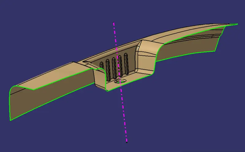
For creating the main tooling axis we first visually inspect it and Z direction is better for tooling axis. Now to get a proper axis we first create a point in the centre of the circle and then we will make a line along the point at Z direction which will act as a dummy axis.
Along X direction-
We intersect the surface along the YZ plane and since there is only then draw a line with respect to the other wall at an angle greater than 3°.
Along Y direction-
We intersect the surface along ZX plane and then we draw two line which are almost parallel to the dummy axis. Then bisecting the two lines and get the resultant line.
After bisecting both the line we get from both the direction we get the main tooling axis.
-
Side core tooling axis-
After doing the draft analysis we realize that there is need for a side core and thus we made a tooling axis for the side axis using the same procedure.
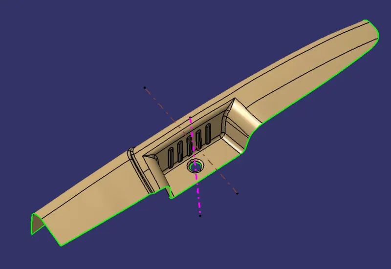
Draft analysis of Class A -
After creating a tool axis we do the draft analysis. Before drafting we have to make sure that in the view mode it is selected to the materials.
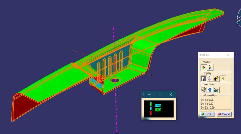
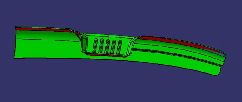
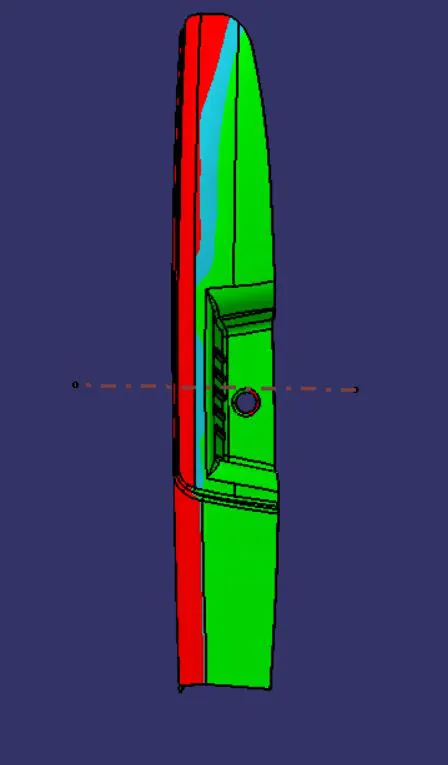
After selecting the feature draft analysis tool we drag the compass from its position to the tool axis. Then lock the compass. After that select anywhere on the component and it will give you the result.
We change the minimum draft for the component to 3°.
We can use the running point option to check the angle of the component.
We can even modify the colour according to our preference.
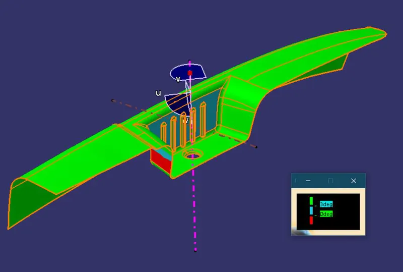
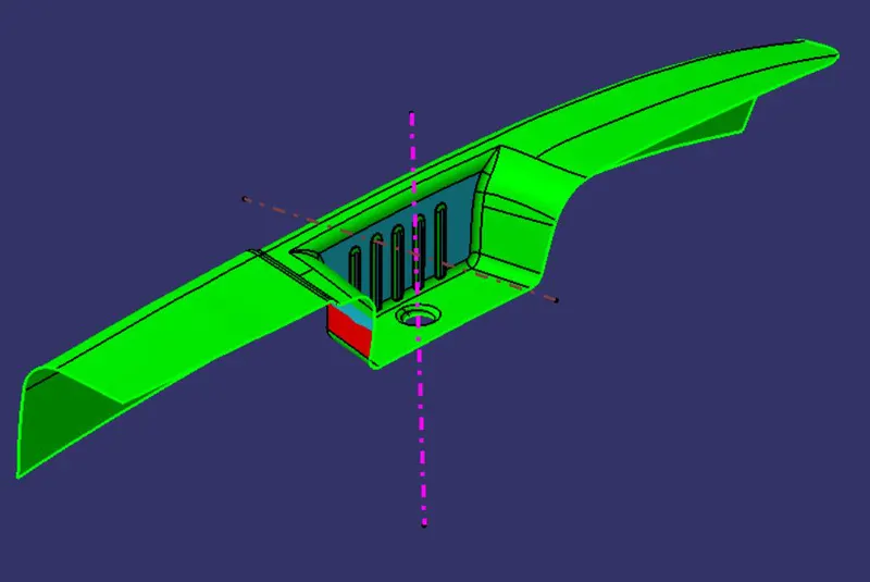
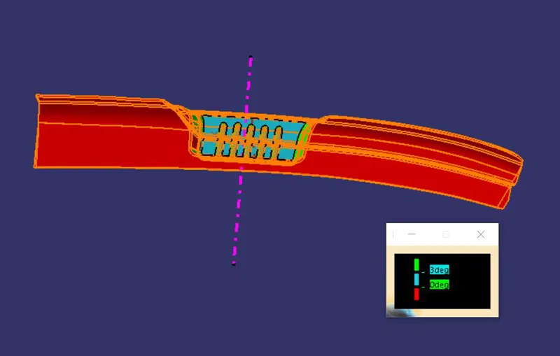
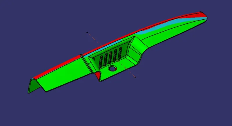
After reading the result we realised that there a need for the another tooling axis or side core so, now we do the draft analysis with respect to the side core tool axis.
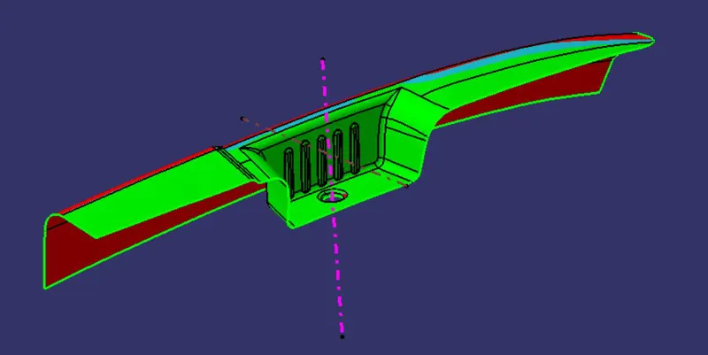
Class B surface-
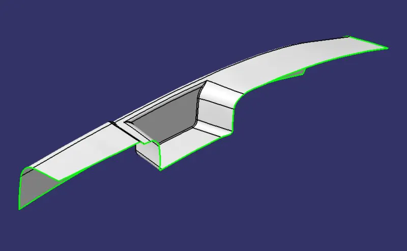
We start creating the class B surface for that the offset all the flat surface to 2.5mm and then we use the untrim tool to untrim the surface and then use the extrapolate tool to extend the surfaces. Then we trim the remaining surfaces and the use edge fillet to fillet the corners.
Class C surface-
First we extract surface edges which are horizontal and use the smooth curve tool to smoothen the curve. Then using the sweep tool we make the c surface with respect to the draft angle. At some edges where we did not use sweep command, we used the multi section surface tool for creating the c surface. We then trim all the surface together to get final c surface.
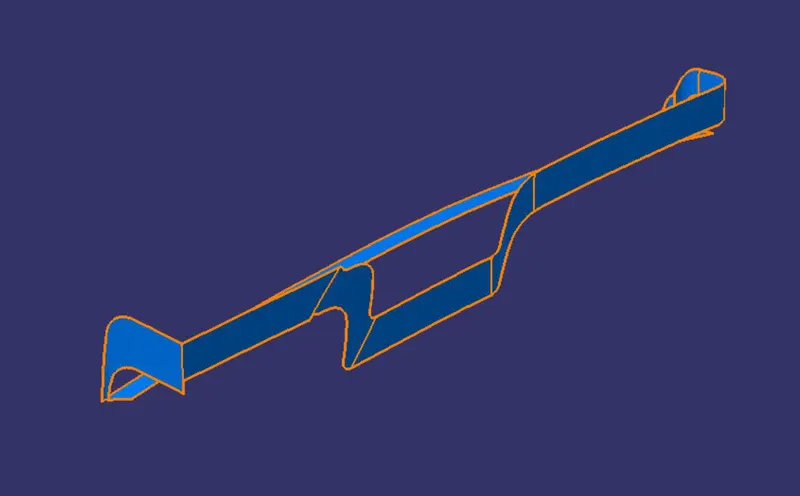
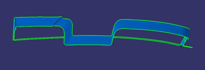
We join the C surface with the A surface.
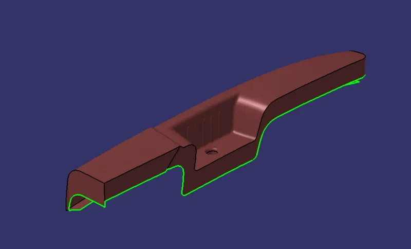
Then we trim that surface with the B surface to make a closed surface component. We can check it using the boundary tool, if it gives an error that means that the component is closed.
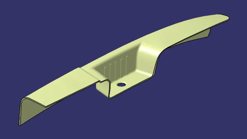
We the go to the part design workbench and use to closed surface tool to create a solid body of the closed surface component. We can also do a draft analysis on that.
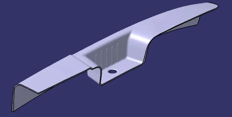
Draft analysis of the component -
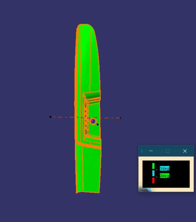
For the solid component also we will follow the same steps as we did for the class A surface with both the tool axis.
1. Main tool axis-
2. Side core Tool axis-
CONCLUSION
With this we got to learn about the draft analysis option and how to create the tool axis for the draft analysis and also to create class B and class C surfaces.