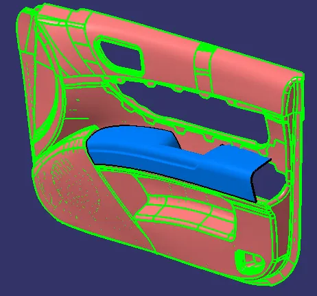
Door Arm Rest Week 8 Challenge
AIM:
The purpose is to model a toolable solid CAD model from the given class A surface of the Door Arm Rest by applying the design rules.
PROCEDURE:
1. Component Study and Tooling Axis Decision
- The model is observed in all 3 directions to decide the best tooling axis direction in order to manufacture the part at a cheaper cost.
- Usually the holes or the flat surfaces are of primary concern to decide the tooling axis. The tooling axis is chosen in such a way that the above mentioned features are also toolable along its direction.
The given class A surface of the Door Arm rest was checked along Y-axis which is perpendicular to the surface. Since most of the part was visbile when viewed along Y-axis and the hole is aligned along this direction, it can be assumed as the tooling axis. However a draft analysis has to be performed to verify if it's the right tooling direction.
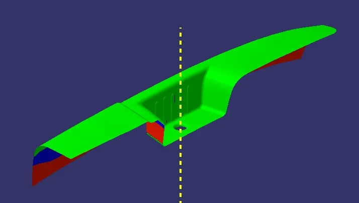
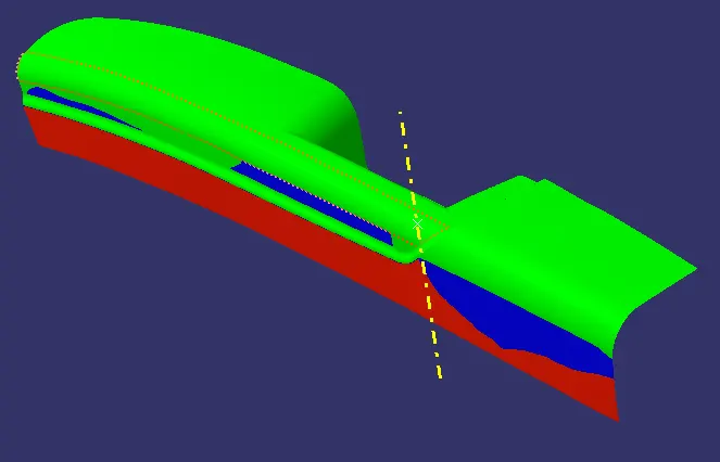
From the above picture, it is evident that the Y-axis can't be considered as a tooling axis.
2. Problematic Regions-
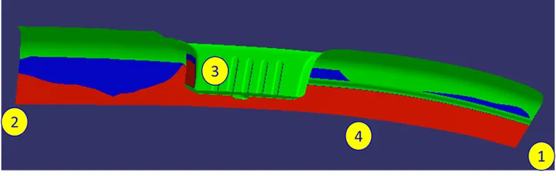
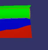
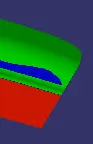
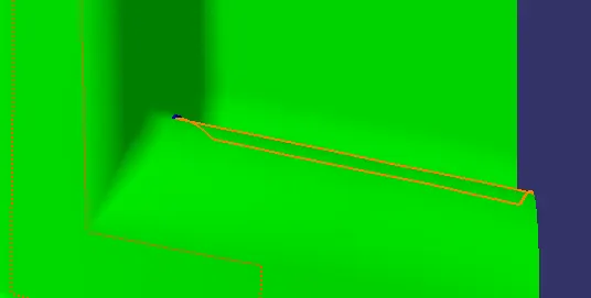
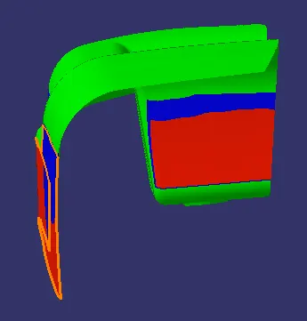
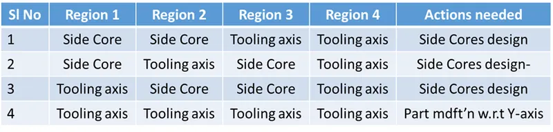
1 2 3 4
3. Solution
These regions can't be cleared along y-tooling direction. Hence the possible solutions are-
- Modifying the tooling direction
- Using Side cores for untoolable features
- Combination of both
Best method can be chosen based on the following factors-
- Cost of improvement (manhours)
- Manufacturing cost (tool and process)
- Part Defects (mold flow, short shot, leakage between side core and molds etc.,)
- Easiness to manufacture and design
- Functionality of the features
- Interference with the environment
Hence the part design can be modifed according to the factors above to make all the features manufacturable. The faulty regions must be communicated to the Class A designer for further modifications.
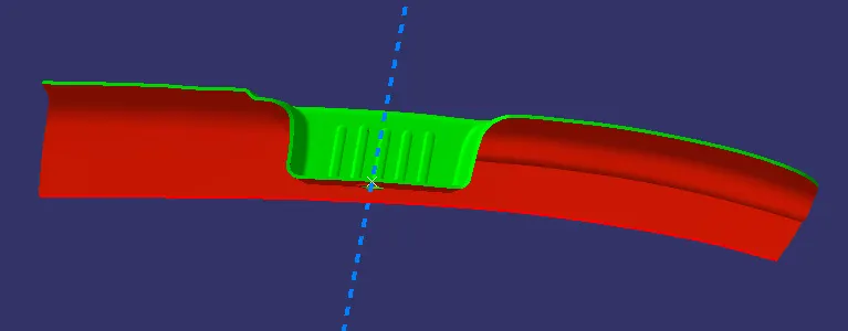
The tilted axes can be considered as Y-axis during manufacturing and to be checked with the factors discussed above.
Method 1- To clear region 3 & 4 along the tooling direction
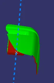
Method 2 - To clear region 2 & 4 along the tooling direction
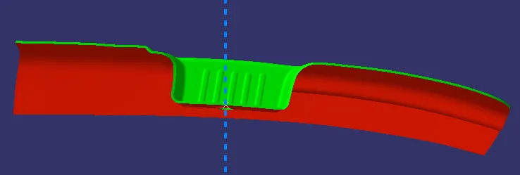
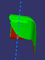
Side core to be used to clear 1 & 3 regions as shown below
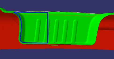
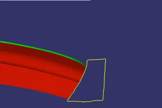
Method 3 - To clear region 1 & 4 along the tooling direction
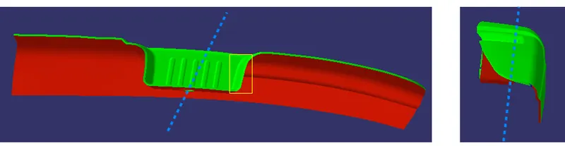
This method created problems to the yellow region to clear the tooling axis. Hence this method can be avoided to save additional cost to manufacture a side core for the yellow region additionally.
Method 4- Modify part
By studying some of the methods identified as discussed above, it is advisable to create a side core for region 1 or modify the class A of that region.
Since the given class A needs some form of correction, i've designed the part in one of the way to make it manufacturable.
3.1 Modifying tooling direction to clear region 3 & 4 and using side cores to clear region 1 & 2
i. Bisecting method
A point is created at the hole center which was used for creating an axis system. Then intersection curves of the part were created w.r.t xz and yz planes. Finally a bisecting line was created w.r.t the intersection curves. Draft Analysis was performed on the part w.r.t the tooling axis created.
ii. Manual Adjustment (6.4 degrees in xz plane and 9 degrees in zy plane w.r.t Y axis)
The compass was adjusted to reduce the red and the blue zones formed in the draft analysis performed on the class A surface w.r.t tooling axis created from the bisecting method.
iii. Draft Analysis
- Draft Analysis was performed on the modified class A surface to analyze if the component is toolable along the tooling axis.
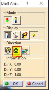
- Feature Draft Analysis (Analysis> Feature Draft Analysis) option is used to perform draft analysis on the component.
- The compass is placed on the created tooling axis using the option in the Draft Analysis tab as shown below.
- Next the component is chosen to perform the draft analysis. The maximum draft angle is chosen to be 3 degrees (standard value).
- The parts highlighted in green have draft angles from 0 to 3 degrees.
Y-axis Bisecting method Manual Adjustment
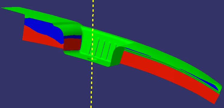
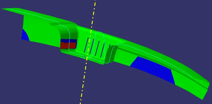
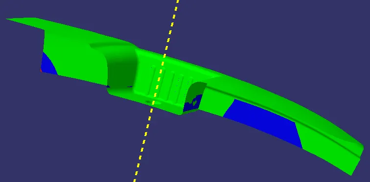
From the above pictures, bisecting method was able to rectify region 4, but the other 3 regions are still an issue.
3.2. A-Surface Correction
Since the A-surface had no errors or discontinuities after joining, no correction was performed on it.
3.3. B Surface Creation
There are 2 ways of creating a B-surface.
- Offseting the B surface to a distance of part thickness (2.5 mm).
- Parametrizing the class A by splitting and trimming the surfaces, and finally offsetting the obtained class A which is discussed below. For this task, i've chosen parametrize method for practice.
- Before creating the B surface, the model is studied to split the whole part into multiple parts for easier modelling.
- Each surface present in each of the parts mentioned above was first extracted from the given class A surface.
- Then these are untrimmed and extrapolated to create an intersection between them.
- These are then offset 2.5 mm from the class A surface, trimmed w.r.t each other and filleted to form the B surface (base of the actual component).
- Fillets were finally created by untrimming the fillet surfaces of class A and measuring the radii respectively.
Skeleton construction
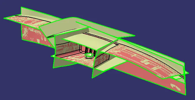
Final Class A surface vs Given class A surface
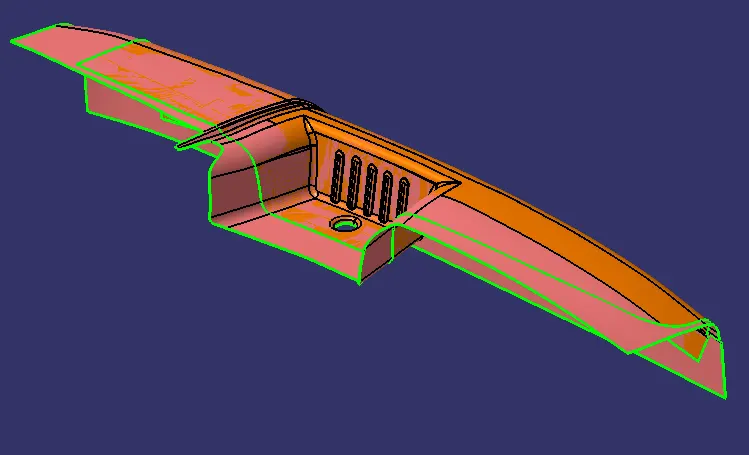
Class B vs Class A
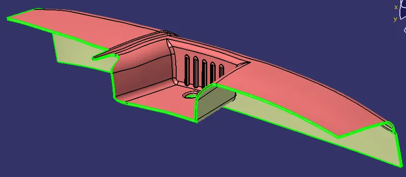
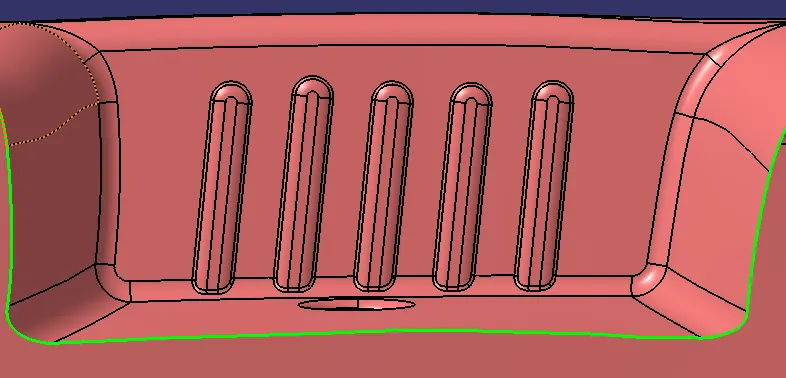
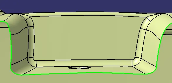
The class B surface is formed with all class A surfaces except the features shown below since its a styling feature which is not required on the B surface.
3.4. C Surface Creation
C Surface is created by trimming of various surfaces created from sweep, multi-section and extrude.
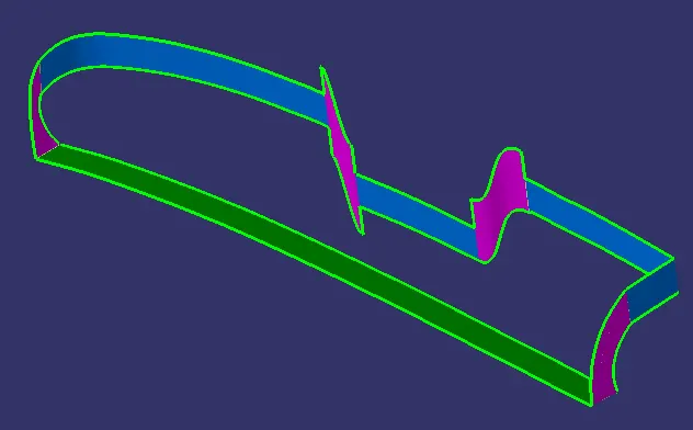
Pink- Multi Section; Blue- Sweep; Green- Extrude
Sweep
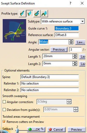
- Boundary of the class A surface is created as highlighted in green in the picture below.
- The surfaces adjacent to the boundary were then extracted to use them for the sweep option in the next step.
- Then the boundary was swept perpendicular to the tooling axis. The following sweep option was used.
Extruded surface
The surfaces which are not inclined along the tooling direction are extruded as shown below.
Multi-section surface
The pink surfaces when swept along the tooling axis produced erroneous surfaces. Hence multi-section was used.
- The boundaries of extruded and swept surfaces were used to create the multi section surfaces.
Finally these were trimmed against each other to form the final C surface. C-surface w.r.t A and B surface is shown below.
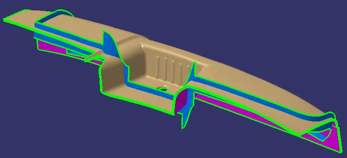
sandalwood- Class A; Pink- Class B ; Blue- Class C
3.5 Surface model creation
- Finally all 4 surfaces were trimmed against each other to form the final surface CAD model.
The following figure shows the surface CAD models generated from the original and modified class-A surface.
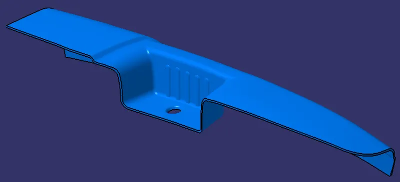
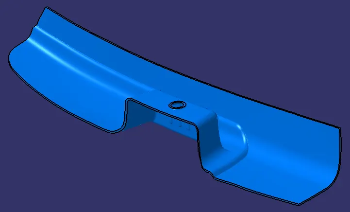
3.6. Part Model Creation
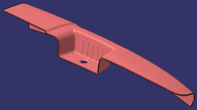
- With the surface model obtained in the previous step, the solid model is obtained by using closed surface option in the part workbench.
3.7 Draft Analysis
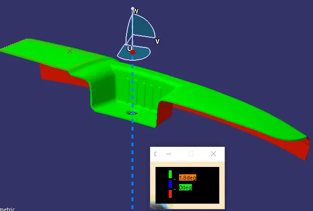
- Draft Analysis was performed for the solid part to check the manufacturing feasibility. Draft Analysis results in filleted region is shown on the right side picture.
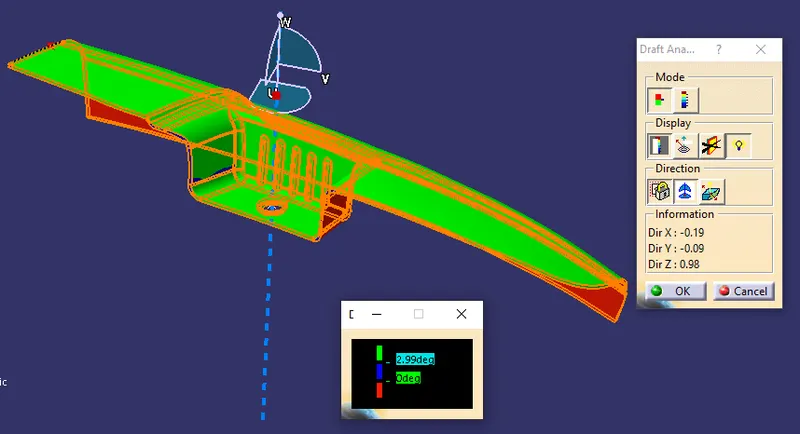
There were few blue zones which can be avoided by considering 30 % design allowance. Hence draft angle was changed to 1.8 degrees which is above the 30% limit.
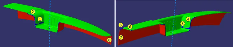
Few of the surfaces are shown below.
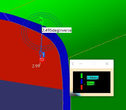
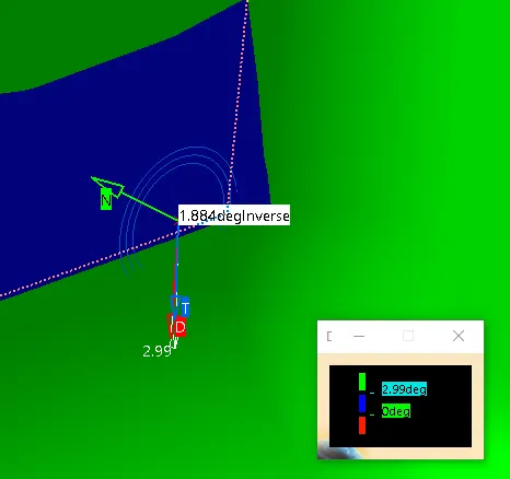
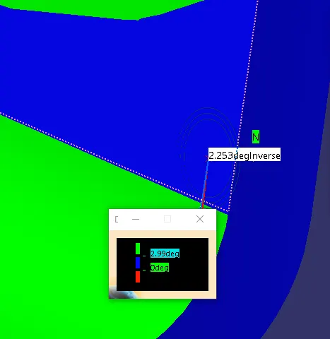
Surfaces after modifying draft angle to 1.8 degrees. There are 2 red zones (undercuts 7 & 8) even after modifying. These can be manufactured with side cores if the feature can't be modified and have crucial functional importance.
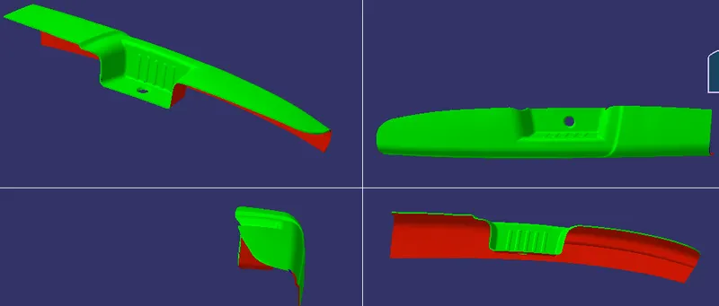
RESULTS
The given part was analysed to decide the tooling direction during which it was identified that the whole part can't be manufactured along the tooling direction. Hence multiple solutions were provided to tackle the issues. Finally a single method was explained as an example for the procedure to follow which can be adopted for the other methods also. Draft analysis was also performed to identify the features manufacturable along the tooling direction and the features that can be included under the 30 % design allowance. The errors in the class A surfaces has to be communicated to the class A deisgner after deciding the method to go for designing based on several factors mentioned in the report.
Views
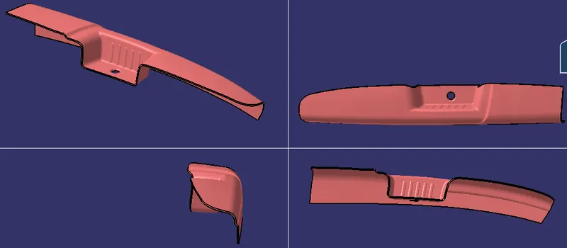
Assembly with door trim