Door Arm Rest Week 8 Challenge
Plastic Product Design: Door Arm Rest (CATIA V5: Generative Shape Design)
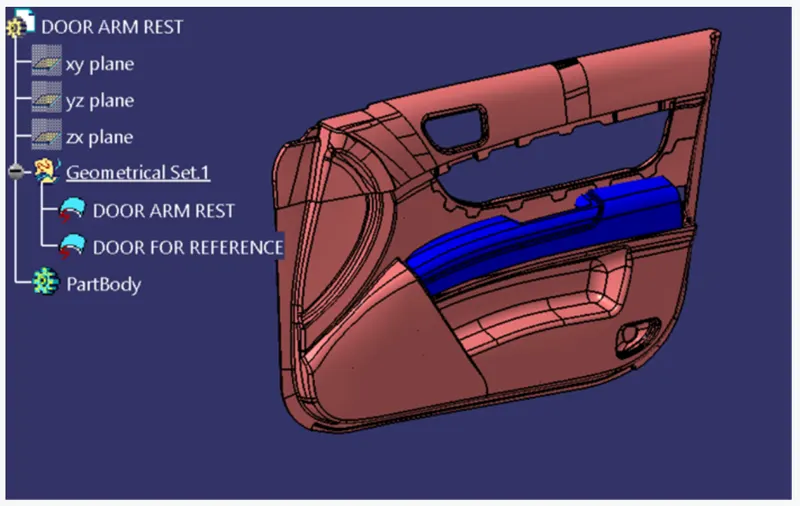
Aim and Objective:
- Creating Tooling Axis following OEM Standards.
- Creating Class B Surface and Class C Surface using the given Class-A Surface as an input.
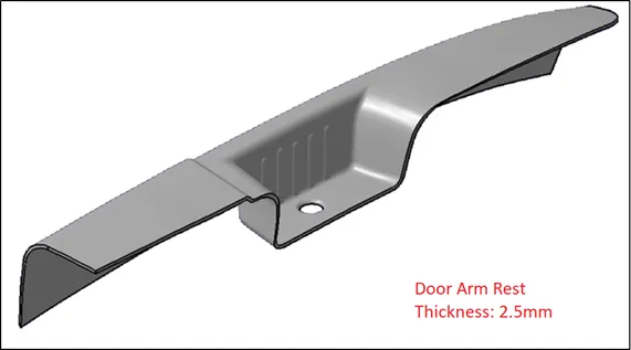
- Making Solid Part of 2.5mm thickness.
- Preforming Draft Analysis.
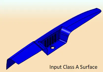
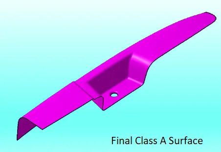
Class A Surface:
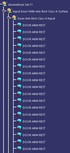
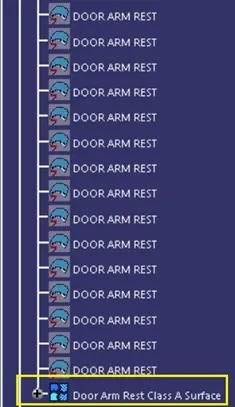
- As an input Class A Surface can be in Distorted form or in Separate parts and we need to correct it.
- Either we can Join those parts together or Extract them and then Trim them together.
- Note: We as plastic design engineers are not allowed to make any changes in Class A Surface.
.
.
.
Tooling Axis Creation:
- Injection moulding includes Core, Cavity, and Sliders to make a plastic product.
- Core, Cavity, and Slider move/side in a particular direction which is called Tooling Axis.
- The tooling axis can be made using either by Bisection method or Plane as a reference.
Bisection Method:
- In a Bisection Method, we take intersection at XY and XZ plane.
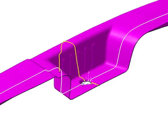
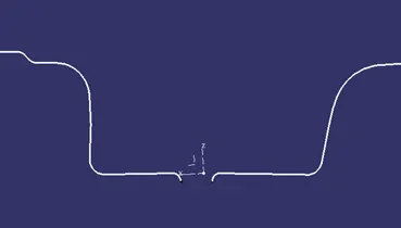
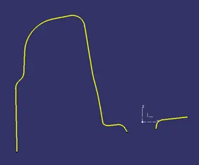
- Using these intersections we make lines that are almost parallel to Z axis.
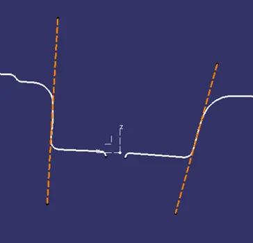
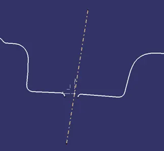
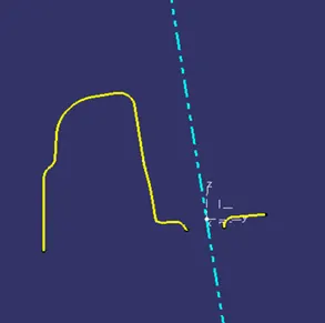
- These lines are then Bisected together to form a Final Tooling Axis.
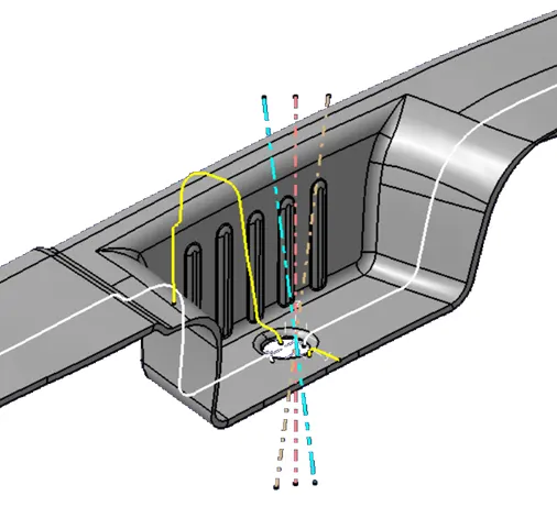
Note: Reference to the above image, Final Tooling Axis is Pink in colour.
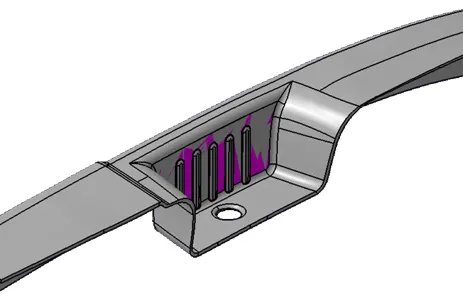
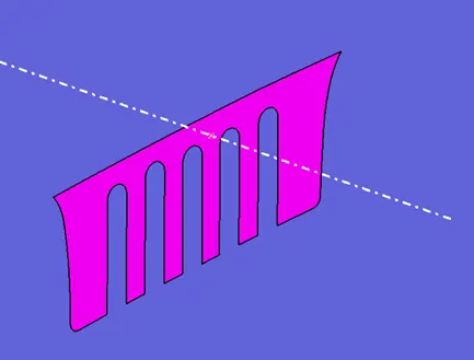
Slider Tooling Axis using Plane as a reference:
- Here a flat face is taken as reference and a point is created at the centre.
- A line is drawn from the point perpendicular to the face.
Class B Surface Creation:
- The surface at which features like Ribs, Screw boss, Dog house, etc. are made to support external mountings is called Class B Surface.
- Class B Surface is made by simply extracting A Surface, offset it to desired thickness and trimming them together.
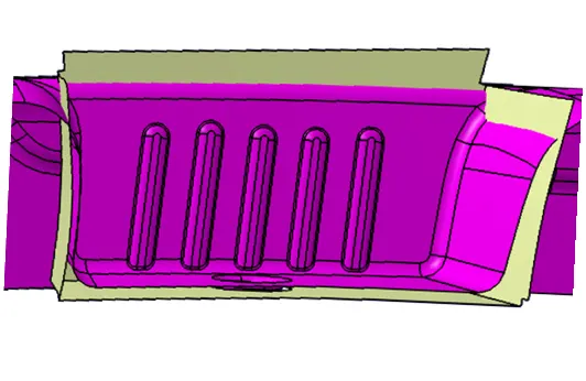
- Fillets are added to the surface at the end to avoid any error.
- The Uniform thickness of the part should be maintained while adding fillets.
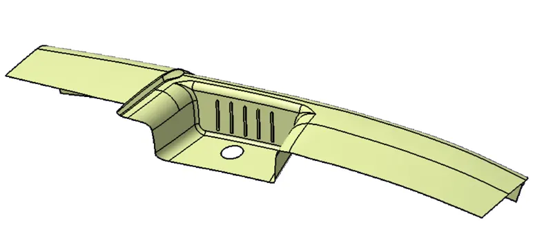
Class C Surface Creation:
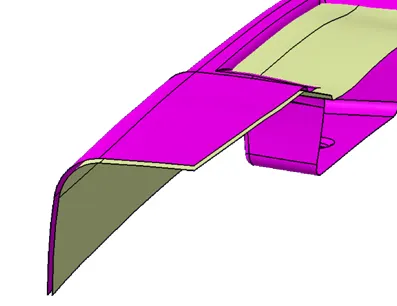
- Class C surface is a connecting surface between Class A and Class B surface.
- Draft angle and Tooling direction are considered while making Class C Surface.
- Sweep with a reference surface is used to create Class C surface.
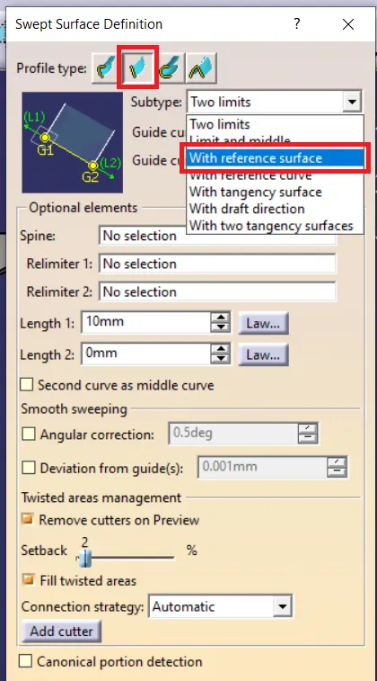
- Class A Surface is taken as a reference surface.
- White Surface indicates Class C Surface.
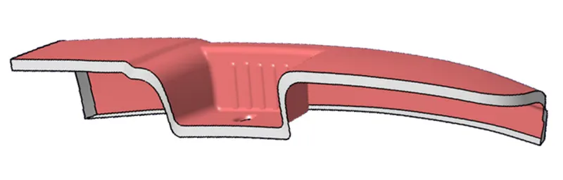
Solid Part With 2.5mm thickness:
- Class A, Class B and Class C Surface are trimmed/ Joined together to form a Final Trim
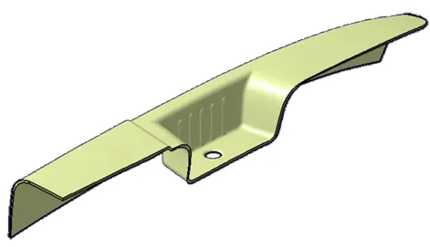
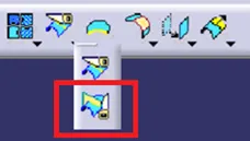
- The final trim is hollow from the inside.
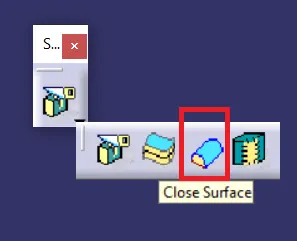
- This final trim is filled with a solid using the Close Surface command. (Mechanical Design > Part Design)
Draft Analysis:
- The draft is an angle provided to the part with respect to the tooling axis to reduce friction between Part and Mould.
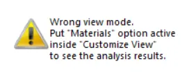
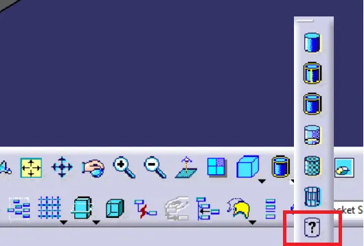
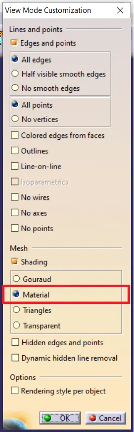
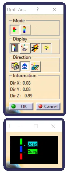
- Before moving towards draft analysis, it necessary to put 'materials' option active inside 'Customize View'
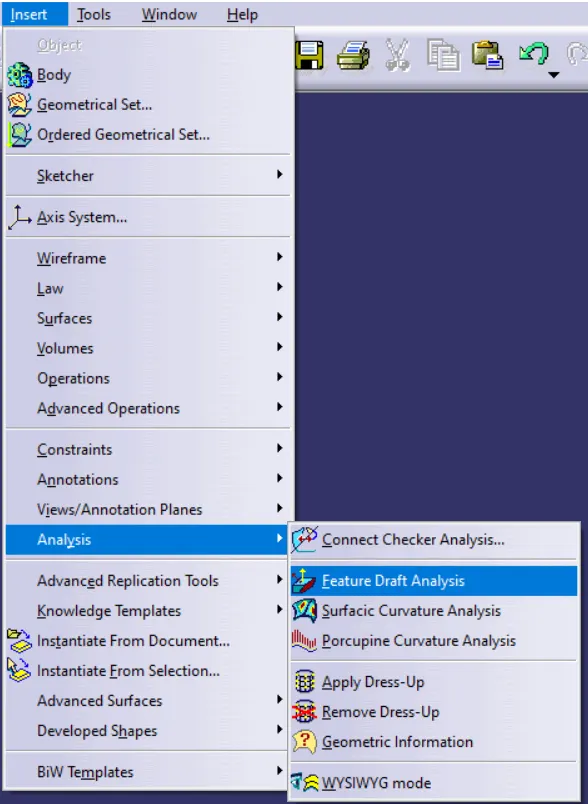
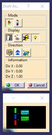
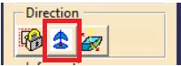
- Select Compass icon on Direction pane
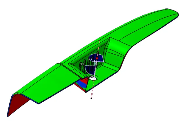
- Move compass on the axis, make sure compass and axis are collinear.
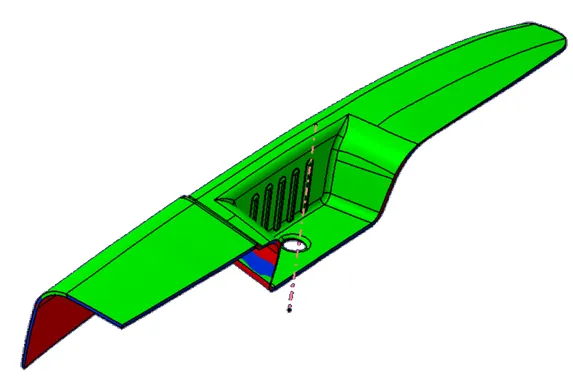
- Part is provided with 3 Degrees of the draft.
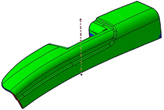
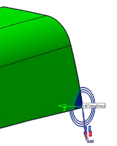
- Area Highlighted has a minimum Draft of 1.87 Degree.
Slider Draft Analysis:
- Pocket Section is provided with a minimum of 3 Degrees of the draft.
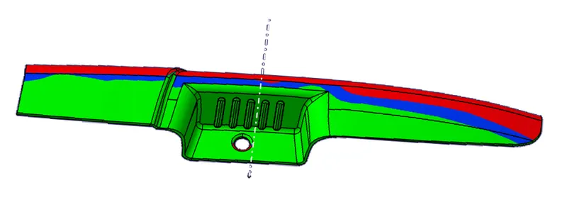
Observations:
- Some area of the Door Arm Rest has Draft angle below 3 Degree (1.88 Degree), which need to be modified to reduce friction and easy operation of mould.
Conclusion:
- Tooling Axis for Door Arm Rest and Slider was created by following OEM Standards.
- Class B Surface and Class C Surface was created using the given Class-A Surface as an input.
- A door Arm Rest of 2.5mm thickness was created.
- Draft Analysis of Door Arm Rest and Slider was performed successfully.
Click/ Browse the Link Bellow for CATpart and PPT.
https://drive.google.com/drive/folders/1k2c-z8fX1S3na73WhmKJT1FC7MsaZnQ_?usp=sharing