Development of Door trim panel
DEVELOPMENT OF DOOR TRIM PANEL
Automotive Plastic Trim:
The design of Automotive Interior and Exterior plastic components is called Trims. The plastic components that you see inside the car are Interior. Ex: Dashboard, Instrument Panel, Doors, seating, and pillars. Plastic components that you see outside of a car are Exterior. ex: bumper, light assembly, hoods.
ABSTRACT
The project report deals with the steps and procedures followed while developing plastic trims for cars door from a class A surface provided, using CATIA V5 surface workbench. It explains the method I followed for creating the main tooling axes, side core axes, Class B surface, Class C surface and final closed body creations. It also explains the draft analysis performed to check the manufacturability of the products using injection moulding. Various plastic door trims such as map pockets, armrest, lower substrate etc were successfully developed in this project.
For this door trim panel development we need to collect the relevant data for ex:-all class A surfaces of parts which are a part of door trim. and required feature profile data etc…,
To fallow the given master section for the attachment features.
INTRODUCTION
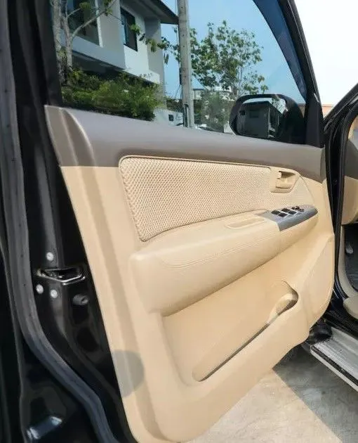
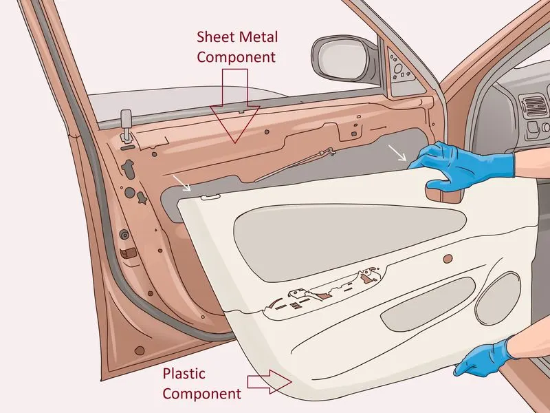
The door panel covers internal parts like the window regulator, the power window motor, and the wiring. It is attached to the sheet metal part of the door. It is designed differently based on the design of the sheet metal part of the door. Besides its aesthetic look, it also has many functional features attached to it such as an armrest, bottle holder, speaker attachment, etc. In older cars, door panels used to be made out of cardboard and upholstered with material that matches the rest of the upholstery within the cabin. On the other hand, most modern cars have door panels made from plastic.
OBJECTIVE
- Here I received class A surface of a car door’s plastic trims. My objective is to develop the class A surface received into manufacturable product design following the OEM design standards using CATIA V5 surface workbench.
STEP BY STEP PROCEDURE:
- CLASS - A SURFACES:
A-class surfaces are those free form surfaces, which are visible to us (interior/exterior), having an optimal aesthetic shape and high surface quality. Mathematically class-A surfaces are those surfaces which are curvature continuous while providing the simplest mathematical representation needed for the desired shape/form and does not have any undesirable waviness. This is the reason why in design industries Class-A surfaces are given more importance. In automotive design, a class-A surface is any of a set of freeform surfaces of high efficiency and quality.
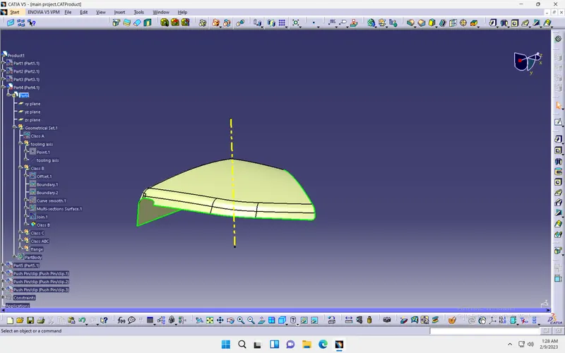
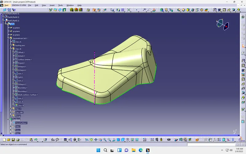
- CLASS - B SURFACES:
Class-B surfaces are the secondary surfaces that can be seen sometimes, but are less important, such as the inside of your glovebox, ash tray, etc. These must be smooth and "error-free" as well, but are not held to the standards that class-A surfaces are.
- CLASS - C SURFACES:
Class C surfaces are the backside surfaces that can have tool marks, flash and other imperfections without hurting appearance, function, etc.
DRAFT ANALYSIS:
- The draft analysis command enables you to detect if the part you drafted will be easily removed. This type of analysis is performed based on colour ranges identifying zones on the analyzed element where the deviation from the draft direction at any point, corresponds to specified values.
- The maximal draft analysis accuracy is 0.01 deg. According to the graphic card performance, this accuracy can be debased.
- The different mapping analyses of the same surfaces cannot be displayed simultaneously, even if you have set the mapping analyzes in no show. You need to visualise them one after the other.
OTHER ATTACHMENT FEATURES
- Dog houses
- Heat stakes
- Flanges
- Locators
- Ribs
- DOG HOUSE :
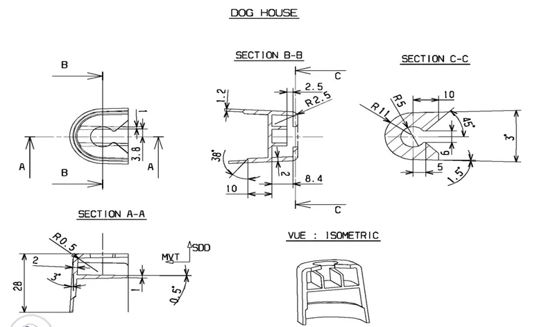
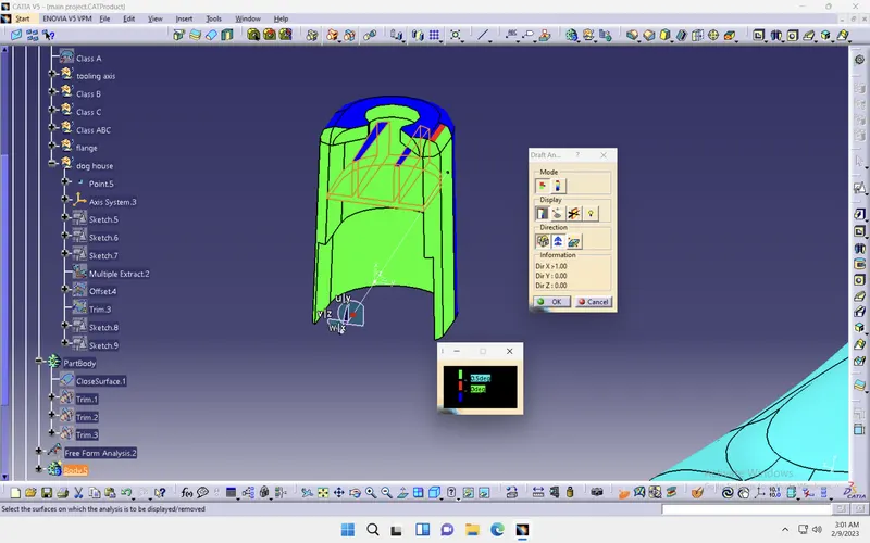
Dog house is an engineering feature used in plastic trim design. Dog houses are used as supporting features. Sometimes other engineering features like snaps; locators etc. are mounted on them to increase their strength. Dog houses are subjected to draft analysis to prevent breakage of the component during ejection from mould cavity. Dog house and other engineering components are built on a B-surface.
- HEAT STAKING :
Heat Staking is a pulsed-heat process to join two or more parts out of which one at least is made of plastic. The process is to deform the plastic material using heat and force at a set process time. The bond is made by partially de-forming the plastic part in order to fix the other.
Heat Staking makes it easy to bond metal to plastic and is commonly used in high volume/low cost applications such as automotive, IT and consumer appliances.
Heat Staking Benefits:
- Similar and dissimilar materials may be joined: metal to metal, plastic to plastic, metal to plastic
- Accurate control operating within a small process window
- Local heating resulting in no damage to surrounding materials
- Processing of glass-filled materials
- No mechanical vibration
- Many heat-stake shapes are possible through custom designed tools.
Materials best suited for Heat staking:
Heat staking technology is ideal for most native and blended thermoplastics on the market today, as well as the most robust glass and/or other- filled plastics. It produces high quality results when used with any of the following materials:
- Polycarbonate (PC)
- Polypropylene (PP)
- Polystyrene (PS)
- Acrylonitrile butadiene styrene (ABS)
- Nylons (GFN or Nylon 6/6)
- Ultem (GFN or Nylon6/6)
- FLANGES:
A flange is a protruded ridge, lip, or external or internal rim that increases strength. A flange allows for easy attachment and transfer of contact force with another object. They help with stabilizing and guiding the movements of a machine or, in this case - your access door
- LOCATORS:
Locators are use to arres the degree of freedom , If it a xy , yx based component we will able to arres the x,y freedom. we are having 12 number of degree of freedom so using of locators to lock it. It is having two different types ,they are two way locator and four way locator.
- RIBS:
Ribs are used to strengthen the walls of your mould without increasing wall thickness which means that you minimise the problems that come into play when the wall thicknesses have to be increased. In essence, if the wall is too thick, warping and sinking can result so that the entire design may need to be rejected.
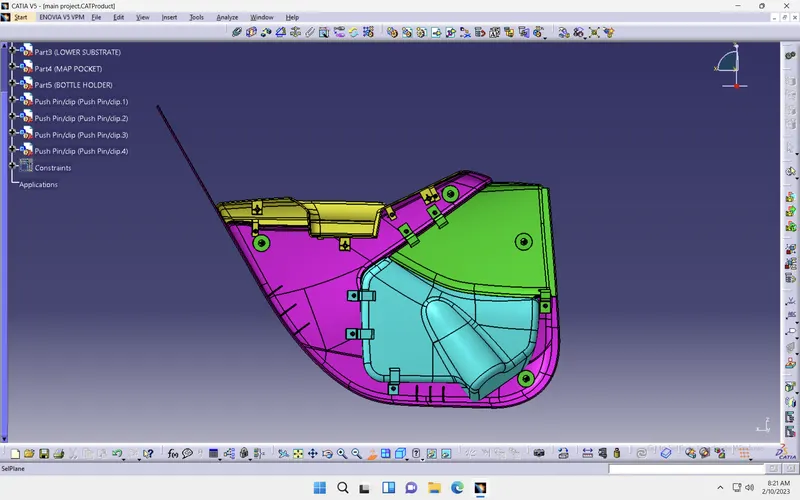
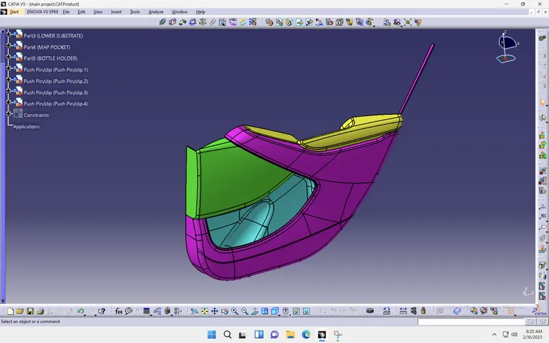
PARTS INVOLVED IN DOOR TRIM PANEL:
- INCLINED ARM REST
- LOWER SUBSTRATE
- MAP POCKET
- BOTTLE HOLDER
STEP 1:Creation of class A surface:-
Class-A surfaces are those free form surfaces, which are visible to us (interior/exterior), having an optimal aesthetic shape and high surface quality. Mathematically class-A surfaces are those surfaces which are curvature continuous while providing the simplest mathematical representation needed for the desired shape/form and does not have any undesirable waviness. This is the reason why in design industries Class-A surfaces are given more importance. In automotive design, a class-A surface is any of a set of freeform surfaces of high efficiency and quality.
|
PART NO. |
INSTANCE NAME |
CLASS A |
|
PART 1 |
INCLINED ARM REST |
|
|
PART 2 |
LOWER SUBSTRATE |
|
|
PART 3 |
MAP POCKET |
|
|
PART 4 |
BOTTLE HOLDER |
|
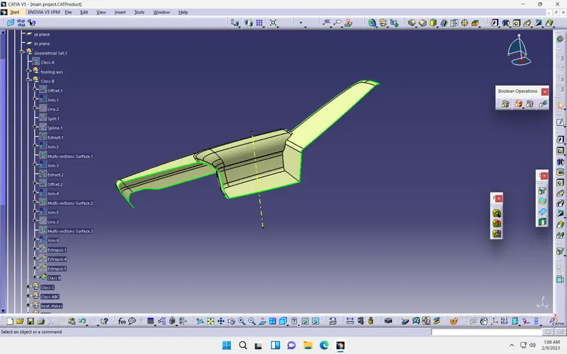
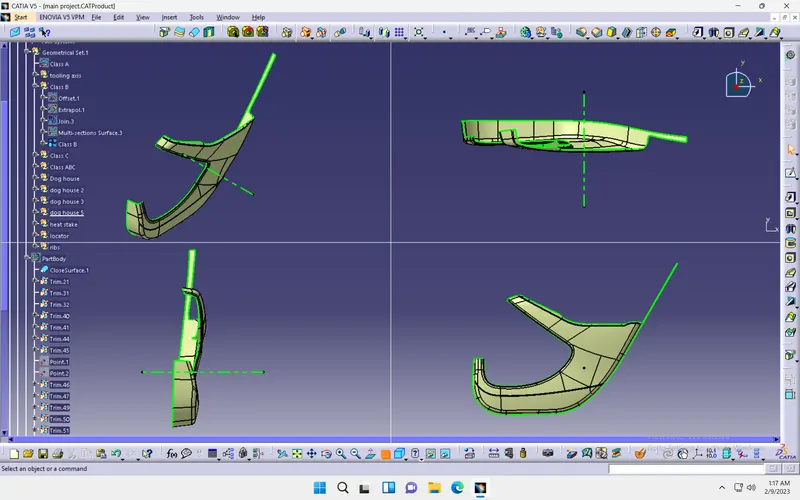
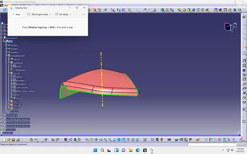
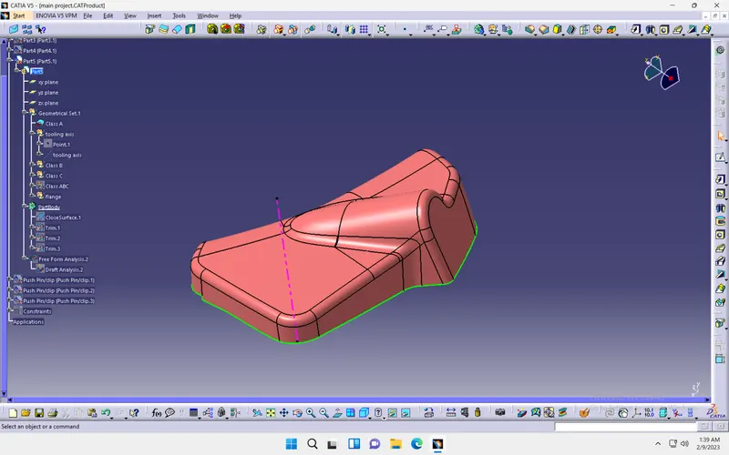
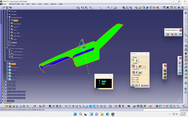
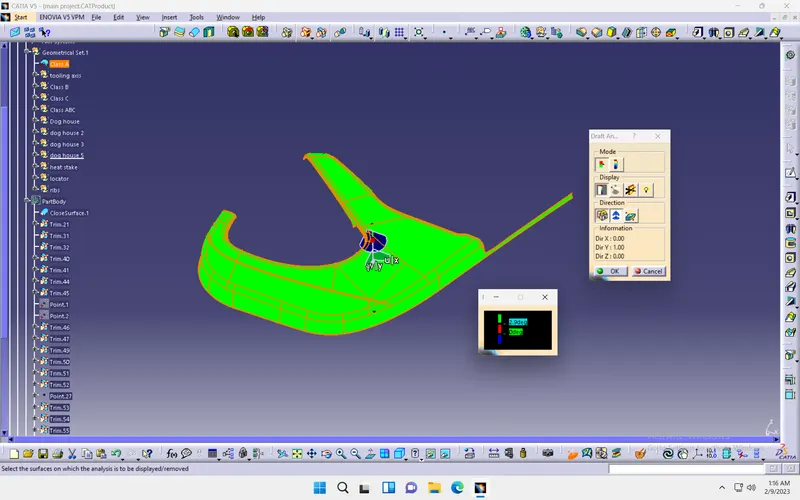
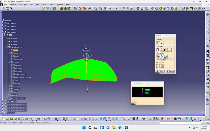
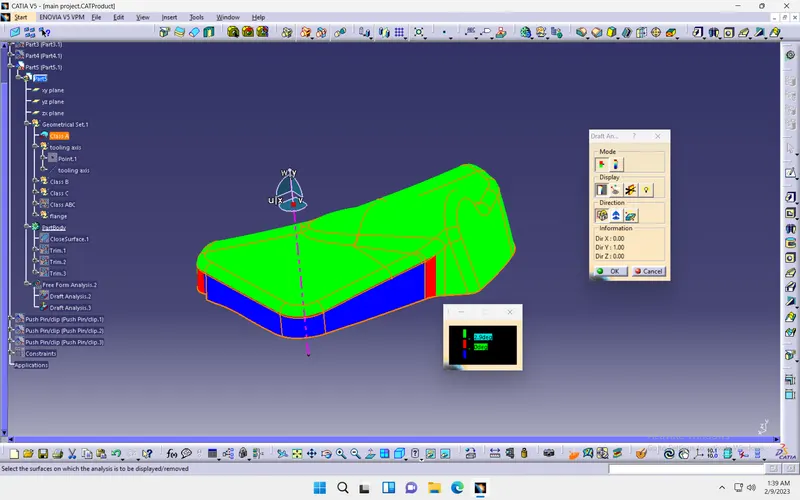
STEP 2:-Creation of tooling axis& Draft analysis
- Due to the complexity of the geometry, the Bisecting method won't be accurate and also takes too much time and effort.
- Therefore, it is best to go with the Compass Method:
- Insert > Analysis > Feature Draft Analysis
- Simply place the compass on the largest flat surface.
- Check the Analysis.
- Tilt the Compass by Orientation or Rotation about an axis to get the desired result.
- After finalizing the orientation, lock the compass direction.
- Create a Line, this will be our Reference Axis:
- Line > Point-Direction > Select Point > Select Direction (Compass Direction)
|
Colour |
Description |
Value |
|
Green |
Core Side |
Above 3 degrees |
|
Blue |
Parting Line |
0 degrees |
|
Red |
Cavity Side |
Below 0 degrees |
Tooling axis:-
|
PART NO. |
INSTANCE NAME |
TOOLING AXIS |
|
PART 1 |
INCLINED ARM REST |
|
|
PART 2 |
LOWER SUBSTRATE |
|
|
PART 3 |
MAP POCKET |
|
|
‘ PART 4 |
BOTTLE HOLDER |
|
STEP 3: B SURFACE CREATION
Note: Depending on the geometry, the extraction and offset of the fillets might generate non-uniform thickness. So it is advisable to extract only the flat surfaces and then apply fillets at the end of Class B formation.
Perform the following operations in the order:
|
EXTRACT |
Choose the respective A surface and extract with no propagation option. |
|
UNTRIM |
The extracted surface will possess the specific trimmed. Untrim to get the basic geometry. |
|
EXTRAPOLATE |
The surfaces have to overlap each other in order to facilitate trimming therefore extrapolate it up to the required dimension. |
|
TRIM |
Trim the surfaces according to the required geometry. |
|
OFFSET |
Note: Offset the Silent Fillet separately and then trim with the bucket |
|
FILLET |
|
Note: The fillet radius of the Class B offset is altered to maintain the uniform thickness throughout the geometry.
|
Offset direction |
Fillet Radius |
|
Inward |
Initial Radius - Thickness |
|
Outward |
initial Radius + Thickness |
CLASS B SURFACES:
|
PART NO. |
INSTANCE NAME |
CLASS B |
|
PART 1 |
INCLINED ARM REST |
|
|
PART 2 |
LOWER SUBSTRATE |
|
|
PART 3 |
MAP POCKET |
|
|
‘ PART 4 |
BOTTLE HOLDER |
|
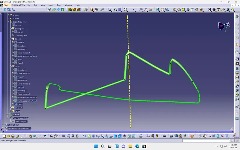
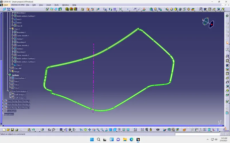
STEP 4: C SURFACE CREATION
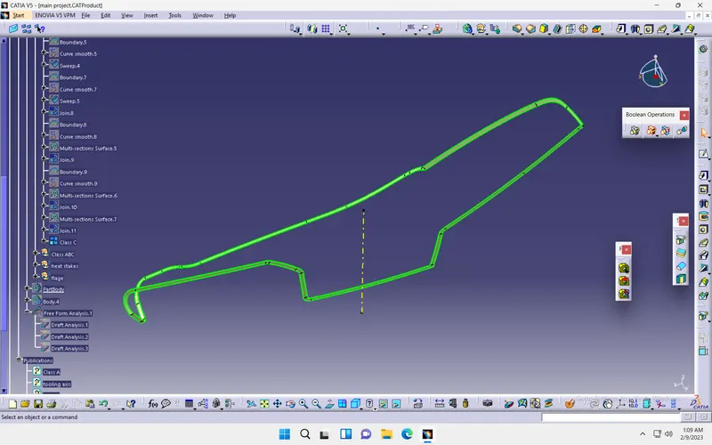
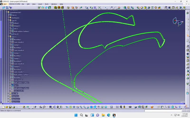
C surface is the part of the geometry that connects Class A with B surface.
Rules to be followed. for C surface creation:
- A minimum draft of 3 degrees should be provided to facilitate the Ejection of the Molded component.
- The parting line should be on the B surface. This means that the draft should sweep outwards, from the C surface.
Perform the following operations in the order:
|
MULTIPLE EXTRACT |
Extract only the Boundary by Tangential selection. |
|
CURVE SMOOTH |
We need minimum Parting lines as possibles, so smoothen the extracted boundary. |
|
SWEEP |
The C surface is swept with the Line option along the Drafting Angle Direction.
|
|
MULTI-SECTIONS SURFACE |
In places like Fillets where the Sweep option doesn't work, we can fill in the gap using MSS.
|
|
EXTRAPOLATE |
The Sweeps at the edges need to overlap in |
|
JOIN |
For our future reference, we can Join all the C surface sweeps as one single entity. |
CLASS C SURFACE:-
|
PART NO. |
INSTANCE NAME |
CLASS C |
|
PART 1 |
INCLINED ARM REST |
|
|
PART 2 |
LOWER SUBSTRATE |
|
|
PART 3 |
MAP POCKET |
|
|
‘ PART 4 |
BOTTLE HOLDER |
|
STEP 5: CLOSED SURFACE
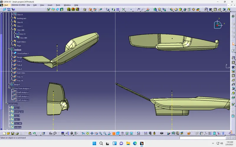
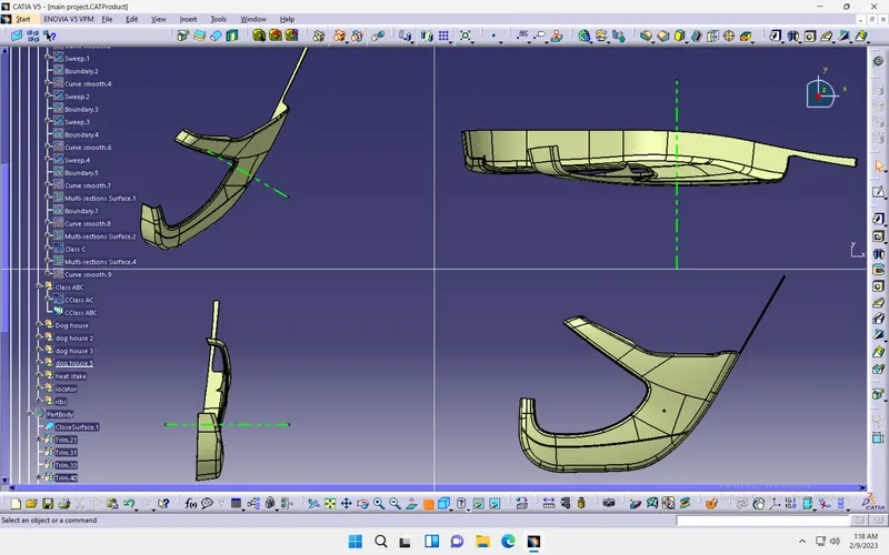
- First Trim/Join Class A with Class C.
- Then Trim with Class B and keep the respective surfaces.
|
PART NO. |
INSTANCE NAME |
CLOSED SURFACES |
|
PART 1 |
INCLINED ARM REST |
|
|
PART 2 |
LOWER SUBSTRATE |
|
|
PART 3 |
MAP POCKET |
|
|
‘ PART 4 |
BOTTLE HOLDER |
|
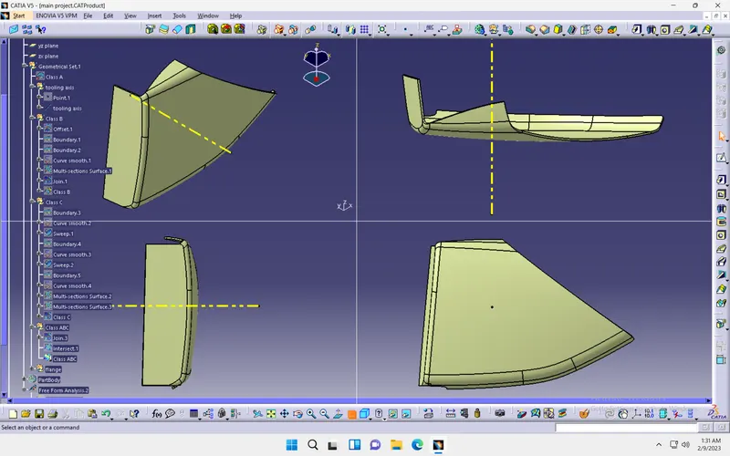
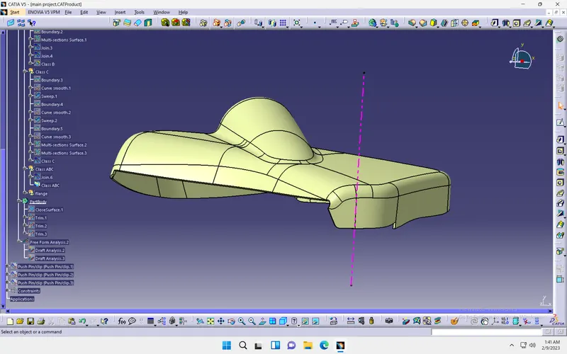
STEP 6: CLOSED BODY DRAFT ANALYSIS
All the 3 class surfaces must pass in this analysis.
Insert > Analysis > Feature Draft Analysis
Note: Ensure you have the Material view mode ON.
- Define the Draft direction using the "Compass" option.
- Drag the Axis system representation close to the model and align it along the tooling axis.
- "Lock" the Draft direction.
- Set the Colour scale
|
Colour |
Description |
Value |
|
Green |
Core Side |
Above 3 degrees |
|
Blue |
--- |
0 degrees |
|
Red |
Cavity Side |
Below 0 degrees |
- Place the Analysis Tool (Arrow Icon) anywhere on the model and review the colours on the feature.
- If any feature (especially C surface) is showing Blue/Red then choose the same option again (It will switch to Analysis under Running point) and place it on the respective feature to review the deviation of the sweep angle from the Tooling Axis.
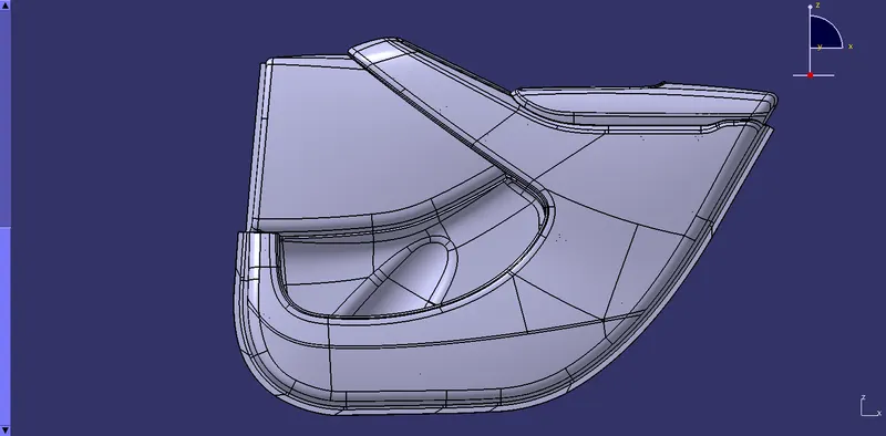
STEP 7: ASSEMBLE THE ALL THE CLOSED PARTS
STEP 8: PLASTIC FEATURE: DOG HOUSE
DEFINITION
- It is a feature used:
- To avoid sink marks.
- Solve length issue.
- Provide strength and assembly.
DESIGN GUIDELINES FOR DOG HOUSE
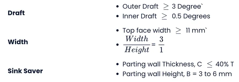
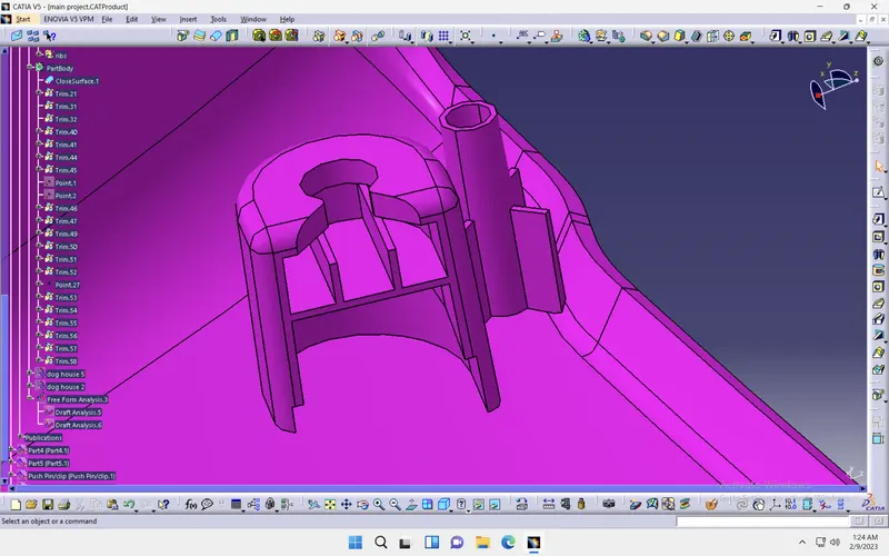
DRAFT ANALASYS FOR DOG HOUSE
STEP 9: PLASTIC FEATURE: HEAT STAKE
GUIDELINES FOR HEAT STAKE DESIGN
|
Diameter |
|
|
Thickness |
|
|
Height |
|
|
Draft |
|
|
Flat plate |
|
|
Clearance |
|
|
Spacing |
|
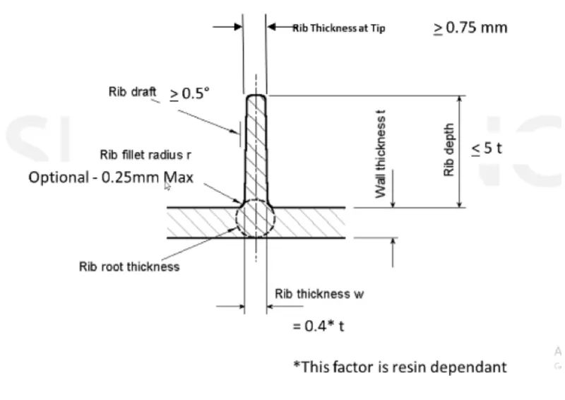
GUIDELINES FOR RIB DESIGN TO SUPPORT HEAT STAKES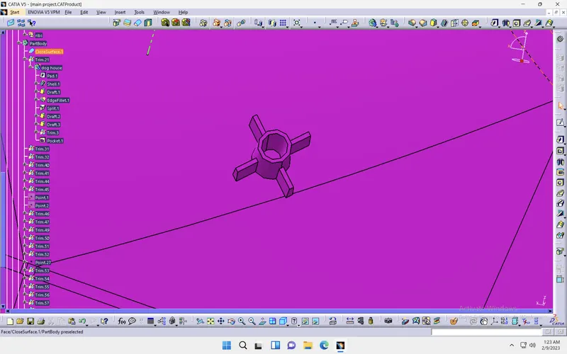
|
Draft |
|
|
Thickness |
|
|
Fillet |
|
|
Height |
|
|
Base Rib Root Dia |
|
Operations to be followed:
|
Extrude |
|
|
Thickness |
|
|
Draft |
|
|
Boolean |
|
|
Fillet |
|
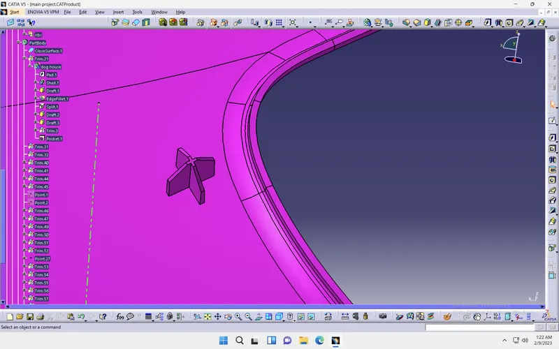
STEP 10: PLASTIC FEATURE:LOCATOR
STEP 11: TRANSLATION OF PLASTIC FEATURES
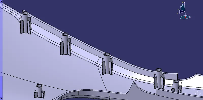
- After creating a single feature, we can translate it multiple times to the desired location.
- First Copy the respective feature's part body into the main part file:
- Copy > Paste Special > As specified in Part Document
- This removes the Parent-Children relationship and we can edit the translated part according to our needs.
STEP 12: BOOLEAN OPERATION
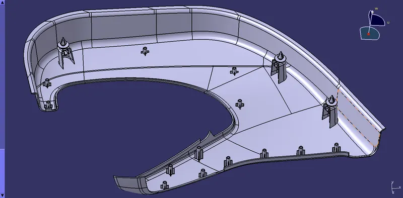
- We have to add all the translated features to the Main body of the Substrate.
- The Union Trim operation fit the best option for our needs.
- Define the Main part body as the Working Object.
- Select Feature Body > Union Trim > Select Faces to remove/keep
STEP 13: CLEARANCE FOR HEAT STAKES PROVIDED ON FLANGES
- The door trim Assembly has to be rigidly fixed as one unit.
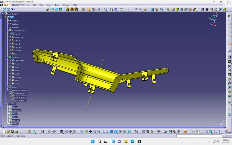
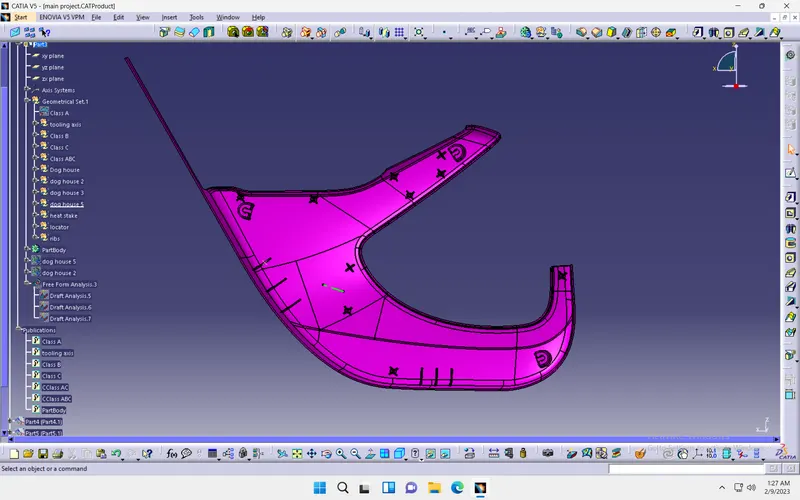
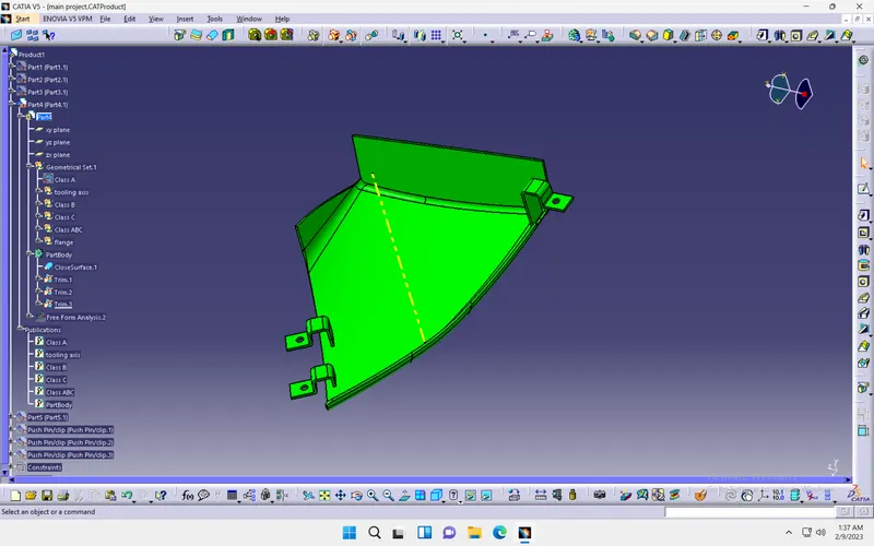
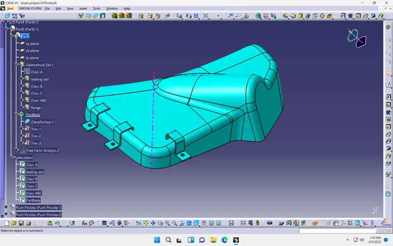
- The 4 components will be permanently arrested to the Lowered substrate by using the Heastakes.
- The Heatstakes will pass through the flanges of the components, therefore some clearance of 0.1mm has to be provided.
|
PART NO. |
INSTANCE NAME |
FLANGES |
|
PART 1 |
INCLINED ARM REST |
|
|
PART 2 |
LOWER SUBSTRATE |
|
|
PART 3 |
MAP POCKET |
|
|
‘ PART 4 |
BOTTLE HOLDER |
|
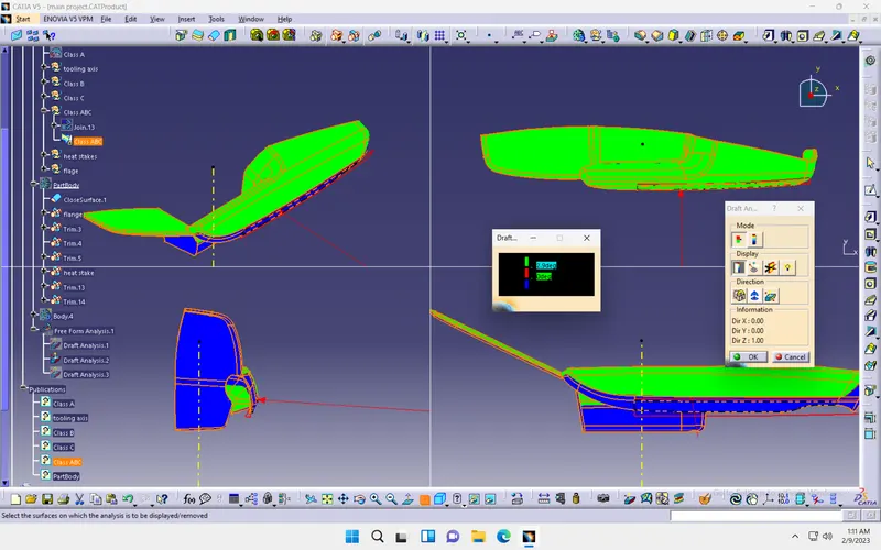
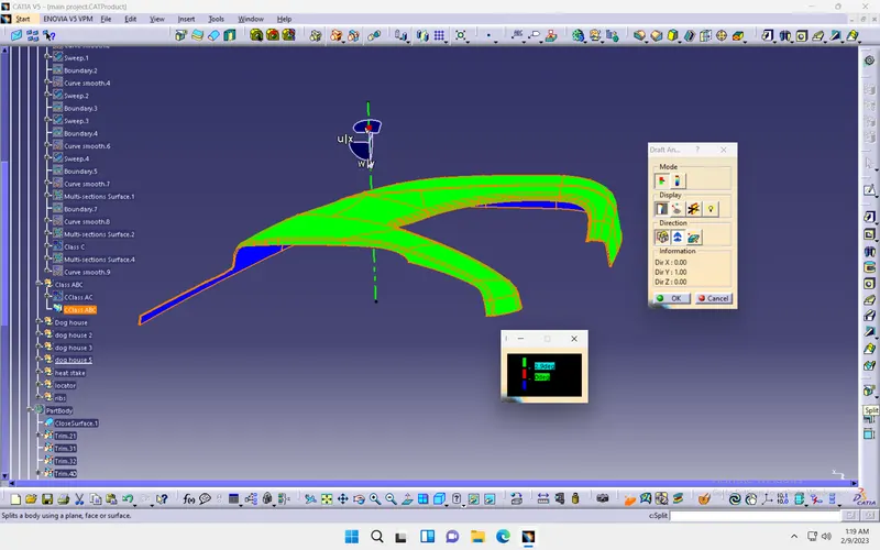
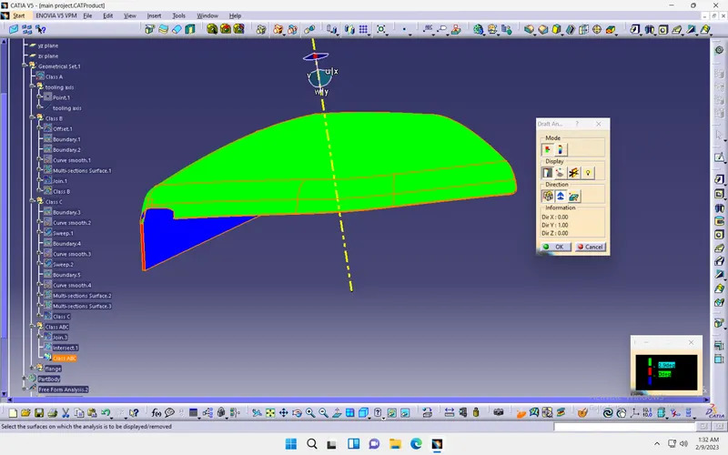
STEP 14: FINAL DRAFT ANALYSIS
Insert > Analysis > Feature Draft Analysis
Note: Ensure you have the Material view mode ON.
- Define the Draft direction using the "Compass" option.
- Drag the Axis system representation close to the model and align it along the tooling axis.
- "Lock" the Draft direction.
- Set the Colour scale
|
Colour |
Description |
Value |
|
Green |
Core Side |
Above 0.5 degrees |
|
Blue |
Parting Line |
0 degrees |
|
Red |
Cavity Side |
Below 0 degrees |
- Place the Analysis Tool (Arrow Icon) anywhere on the model and review the colours on the feature.
- If any feature is showing Blue/Red then choose the same option again (It will switch to Analysis under Running point) and place it on the respective feature to review the deviation of the sweep angle from the Tooling Axis.
|
PART NO. |
INSTANCE NAME |
FINAL DRAFT ANALASYS |
|
PART 1 |
INCLINED ARM REST |
|
|
PART 2 |
LOWER SUBSTRATE |
|
|
PART 3 |
MAP POCKET |
|
|
‘ PART 4 |
BOTTLE HOLDER |
|
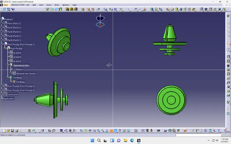
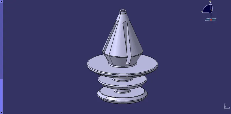
STEP 15: PLASTIC FEATURE: PUSH PIN
DEFINITION
- It is a feature that facilitates:
- Locating and Arresting components of an Assembly.
- Providing Alignment in Mating Parts.
- Acting as a stopper or guide for various mechanisms.
DESIGN GUIDELINES FOR PUSH PIN
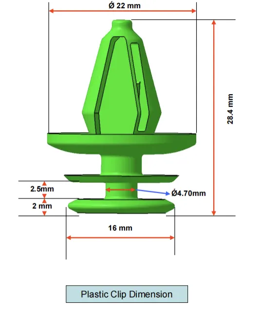
Operations to be followed:
|
Positioned Sketch |
|
|
Revolve/Shaft |
|
|
Pad |
|
|
Boolean Remove |
|
|
Chamfer |
|
|
Fillet |
|
RESULT
- The A surface of the following components converted to a solid body:
- Arm Rest
- Map Pocket
- Lower Substrate
- Bottle holder
- Each component has a uniform thickness of 2.5mm.
- The components' surfaces (A, B & C) pass for Drafting analysis.
- The Plastic features follow the design guidelines and pass for the Lifter draft analysis.
- Clearance is provided on the Flanges, allowing for the Heatstakes to arrest and form an Assembly.
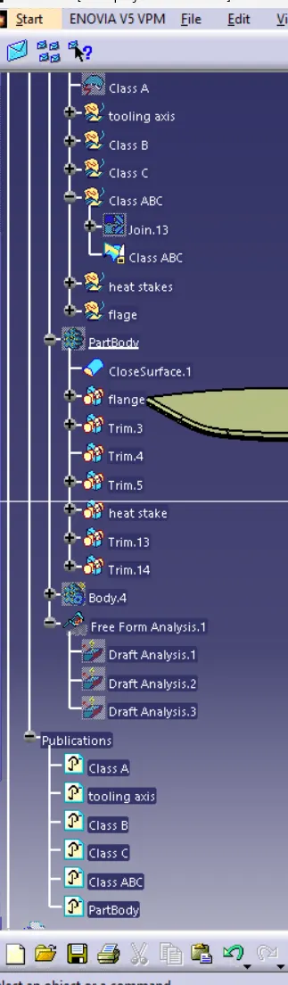
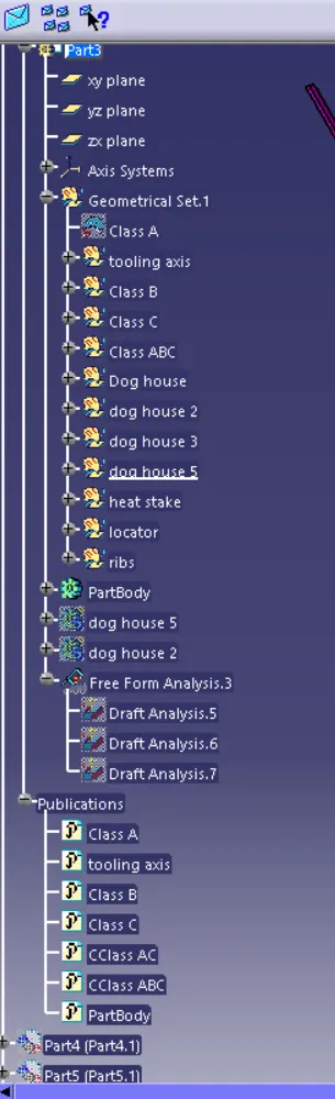
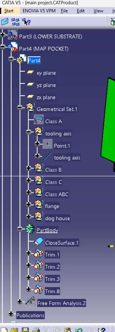
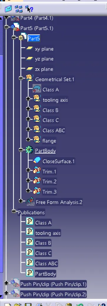
|
PART NO. |
INSTANCE NAME |
FIRST ANGLE VIEW |
TREE STRUCTURE |
|
PART 1 |
INCLINED ARM REST |
|
|
|
PART 2 |
LOWER SUBSTRATE |
|
|
|
PART 3 |
MAP POCKET |
|
|
|
‘ PART 4 |
BOTTLE HOLDER |
|
|
FINAL LOOK OF DOOR TRIM ASSEMBLY
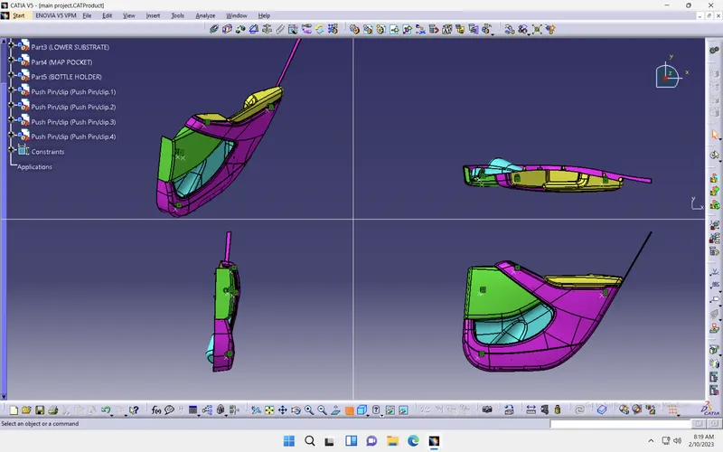
We get the following Desirable Outcome for Draft Analysis:
|
Green |
|
|
Red |
|
Note: Some regions in Lower Map Pocket and Lower substrate fail for draft analysis irrespective of determining the right tooling direction with the compass method.
Therefore, we can conclude that the surfaces of those components have to be re altered by the Class A designer.
CONCLUSION:
By the given master sections and class A reference surface by use of these surfaces we are developed a car door trim by the help of some of attachment features and all the parts can assembled and push pins were also inserted and the final part should be analysed .
Hence, the creation of a plastic car door trim by using CATIA V5 surface workbench successfully.