Attachment Feature Creation (Ribs & Screw Boss)
Creation of a closed surface body and RIBS & SCREWBOSSES by using a given Door Handle stepfile (class A)
AIM:
- To Create the Door Handle Component from the given Class-A surface.
- To Create the tooling axis for the given Class-A Surface meeting the requirements of the draft angle.
- To Attach B side Features in the component.
- To perform the Draft analysis on the model
PROCEDURE:-
Steps requried to complete the closed body surface
- Import the given door handle step file (Class A).
- Creation of a tooling axis.
- Perform draft analasys for class A surface.
- Creation of a class B surface.
- Creation of class C surface.
- Create a combine Class ABC surface.
- Changing the class ABC surface into a solid surface.
- Perform draft analasys for a solid surface.
- Screenshots of the given design in various orientations (Isometric, Front, Side, and Top View)
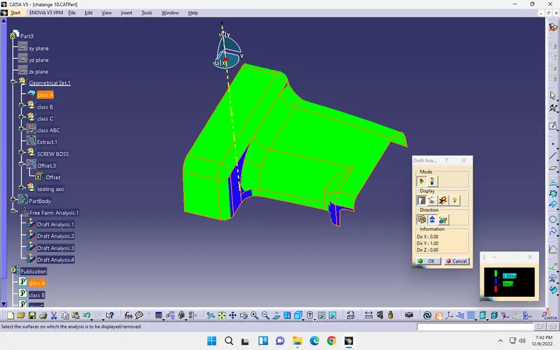
- draft analasys for class A surface
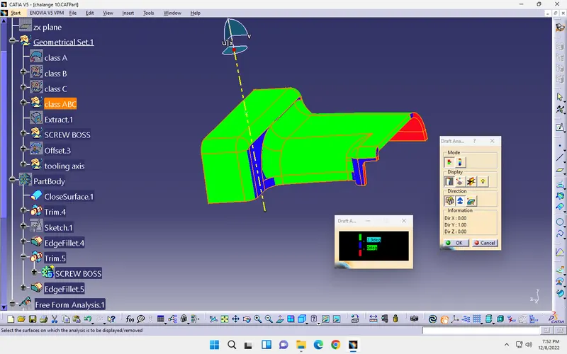
- draft analasys for class ABC surface
- Finel component
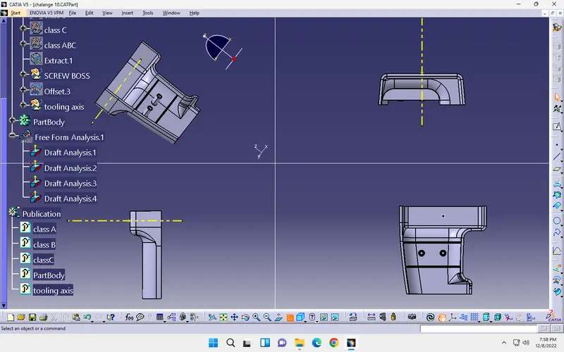
A detailed steps for creation of a closed body by using a surface :
Major tools used for this:
- EXTRACT
- UNTRIM
- OFFSET
- EXTRAPOLATE
- BOUNDARY
- SWEEP
- JOINT
- CLOSED SURFCE
1.EXTRACT: this tool helps to project the surface which you selected in the object that will comes a duplicate as a surface.
2.UNTRIM: this tool helps a object which you extract is there any holes or any corner shapes that eill be rempoved and create a base surface as(rectangle...etc)
3.OFFSET: this tool will helps which a surface you selected that will present at a certain height from a real object
4.EXTRAPOLATE: this tool will helps to provide an additional support from the surface and extend the faces ehich we selected
5.BOUNDARY: this tool will helps the project the object boundary into a plane as it is
6.SWEEP: this tool helps the selected boundary will extrude along certain angle or you will define the tool which you want and along the direction that will be extruded
7.JOINT: this tool help the joint the all surfaces into a one surface.
8.CLOSED SURFACE: this tool is present at a part design app in that and it will change a hallow part to solid part.
METHODOLOGY:
- Steps requried to complete the closed body surface
- Import the given door handle step file (Class A).
- Creation of a tooling axis.
- Perform draft analasys for class A surface.
- Creation of a class B surface.
- Creation of class C surface.
- Create a combine Class ABC surface.
- Changing the class ABC surface into a solid surface.
- Perform draft analasys for a solid surface.
By the above mentinoned steps we can fallow to complete a closed surface body of a base bracket .which we have been normal to surface whare which a core and cavity will ejected without disturbances.
1.Import the given door handle step file (Class A):
from the above mentioned various files we can select a step file of a door handle and click on download then open catia v5 appilication and top left side click files and open the base braket file.and that will called as a Class A.
the door handle will opens like a below shown fig.
then start working on that by fallow the steps which we have above mentioned.
2.Creation of a tooling axis:
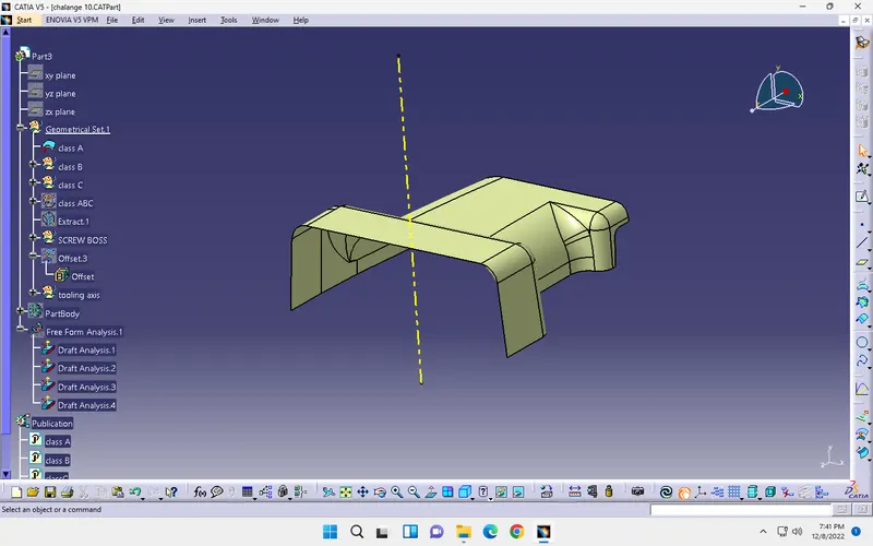
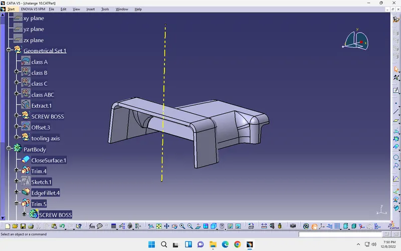
Select the class A surface right click on it and select reframe on it and rotate the base bracket which view we want and select a point and click on an of it plane and ok. then create a line which is passing through the created point up to certain distance then the direction of line to be along z-axis and click on ok .then that line will be called as TOOLING AXIS.
the tooling axis will be shown below
the centre yellow line is nothing but a tooling axis.
3.Perform draft analasys for class A surface:
Which a draft analasys is nothing but a how much angle we requried to make a core and cavity with a secific geometric toolearence and that values should be comes under a draft analasys. first go to insert and click on analasys and select draft analasys and move the compass into the tooling axis and select compass on analasys tab adjust the compas and lock the direction of a compass and click on object then that will show the inclination about tooling axis and we also edit the requried angles which we want and that would varey the colours then the draft angle should be less than that the requried angle.hence the value should be noted for creation of a class C surface.it's about a Draft analasys. since the part get some blue in colour that indicates our given part is wrong then we need to change the design for this we can continue.
Draft analasys:
colour green which is indicates the safer angle to minimise the disturbances through requried draft angle.
4.Creation of a class B surface:
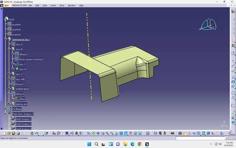
Class B is nothing but a down ward surface of a base bracket which we can see through the down ward direction to create it we can used some of tools like (OFFSET&MULTI SECTION SURFACE,EXTRAPOLATE...etc) by using those tolls we can create the class B surface like same as a class a but small angle will be changed that is called as a draft angle.
class B surface:(with extra portion which is needed to trim). .this is a multi-section surface which is join with a class B
 .
. 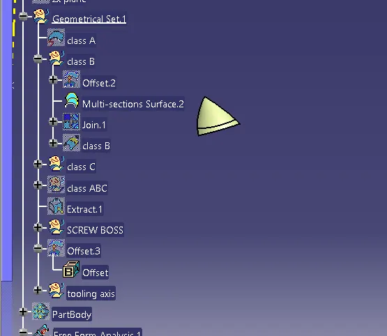
this is a class B surface which is offset from class A at a distance of 2.5mm.
5.Creation of class C surface:
Class C which is a closed part which is joining a class a and class b the middle part of the part is called class C. by creation of a class c surface we need to use the class A surface and use some tools for ex...(BOUNDARY,EXTRAPOLATION,SWEEP.....etc)by the use of those tools we can complete the base bracket at a simple then the class C surface will be created then by useing a joint tool we can connect the all ABC surfaces at a one part.
Class C surface:(3degree of draft angle is provided in outer edges)
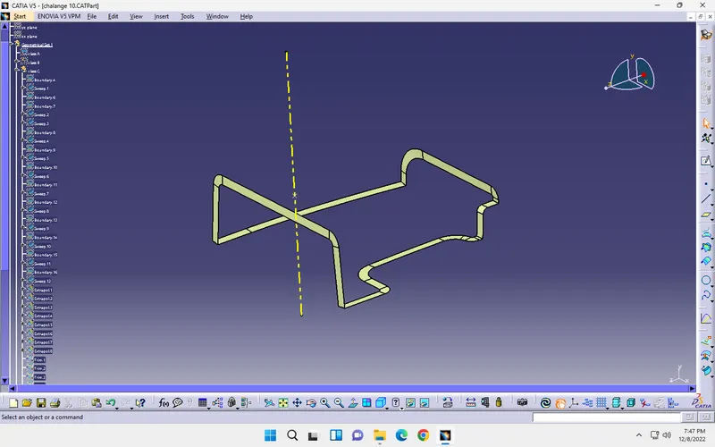
then unhide all class A and class B then joint each other
6.Create a combine Class ABC surface:
by using a TRIM tool we can separate the closed part from the ABC surface and it will be at a shape of door handle and inside of it will be hallow in nature then the final ABC surface eill be created .
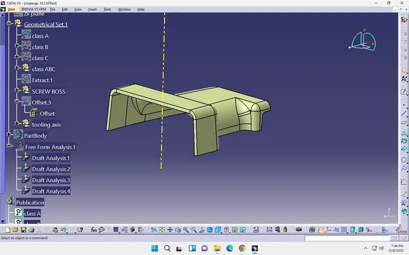
the above part is nothing but a class ABC surface (closed surface) and inside it will be hallow
7.Changing the class ABC surface into a solid surface:
from the surface design we need to change it to a drafting part then we need to move a perticular model into a solid part then open the part design interface and there will be find out a tool called CLOSED SURFACE click on that and ok. then the part will be changed into a solid shape then hide the class ABC surface then priview the finel part.and this will our solid part.
Closed surface:
and this will be our final part and perform once again a draft analasys whrther it is correct or not.
8.Perform draft analasys for a solid surface:
by fallow the same above step 3 and perform draft analasya for a closed surface of ABC and get the final results is it correct or not and suitable for a creation of core and cacvity.the draft analasys may be fallowed by putting an angle of 2.9deggrees.
Draft analasys:
the colours may shows the results under a small tab on below right side.
Then the solid part will be completed by fallow these steps and process.then we need to create a ribs and screw bosses for that closed part.
- STEPS FOR CREATION OF RIBS AND SCREW BOSSES
- Use position sketch to draw the RIB structure
- Pad the ribs with requried dimenshions
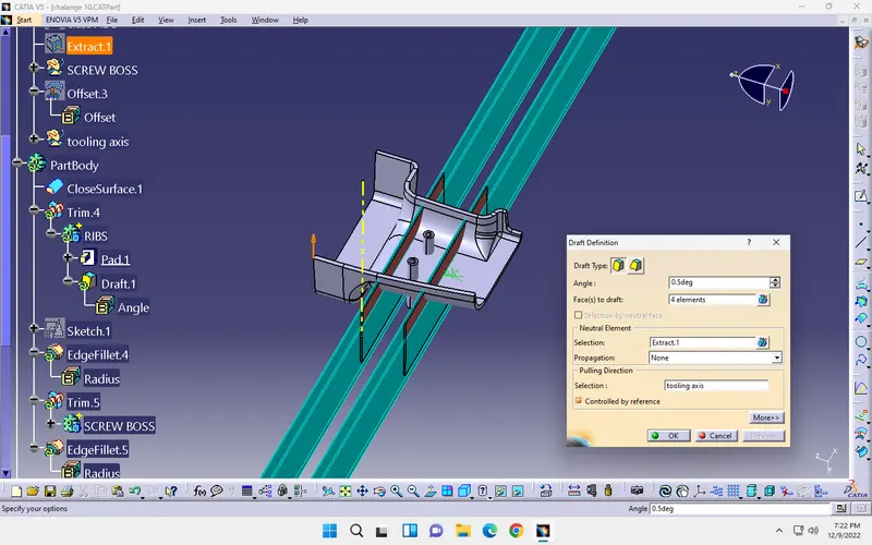
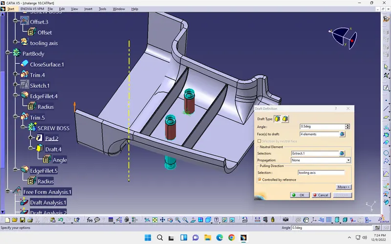
- Draft the ribs with a min draft angle
- join the ribs to a part body and trim un nessary portions
- give edge fillet to the edges of a rib
- perform draft analasys for ribs
same procedure for the screw bosses also and only sketches will be changed and a min draft of 0.5 will placed.and perform draft analasys for screw bosses.
- DESIGN COSIDERATIONS FOR RIBS
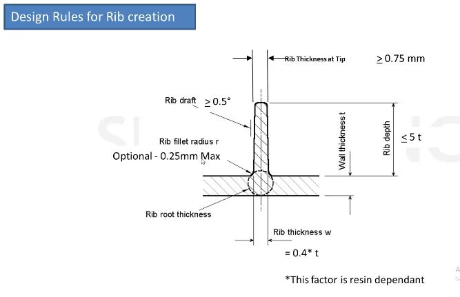
by fallow the rules and design the rib structure for a door handle.
- RIBS & DRAFT OF RIBS
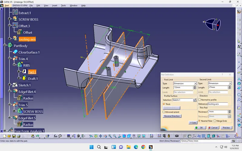 .
. 
- DESIGN COSIDERATIONS FOR SCREW BOSSES
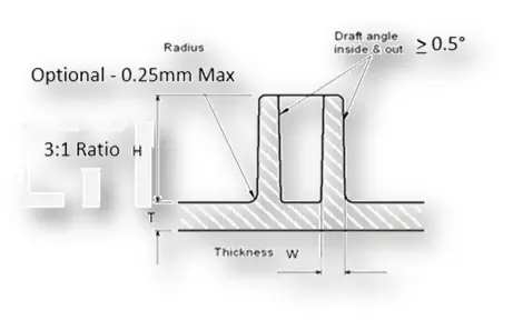
by fallow the rules and design the rib structure for a door handle.
- SCREW BOSSES & DRAFT OF IT
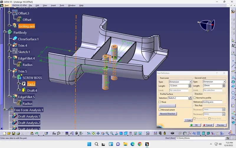 .
. 
And give the relation between ribs and screwbosses to a door handle and perform draft analasys on that.
- DRAFT ANALASYS OF A FINAL PART
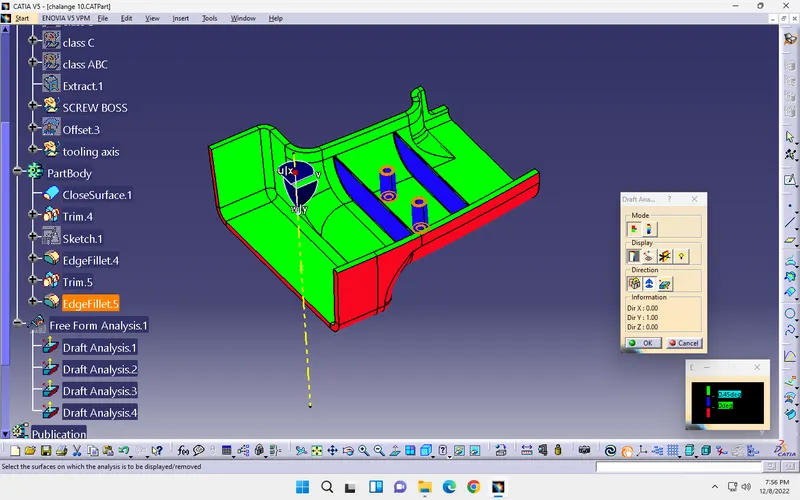
actual draft analasys should be perform then a finel result will like this as shown below
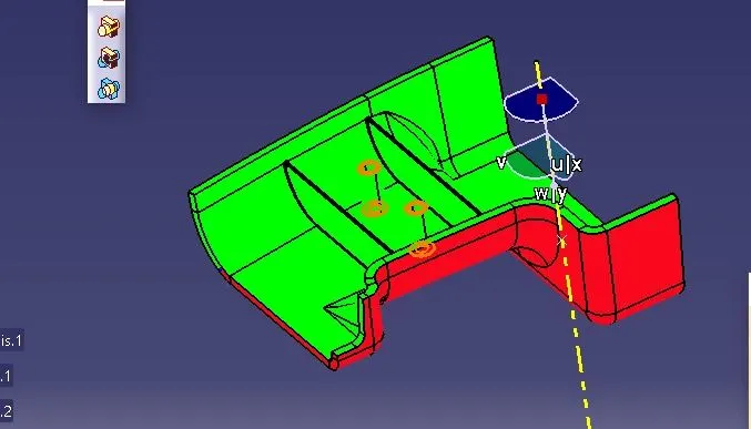
this is the finel part model with a ribs and screw bosses
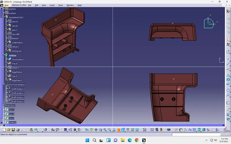
this is about the part model design with a detailed steps
CONCLUSION:
Hence the creation of a closed surface body AND (ribs & screw bosses) by using a given door handle and perform a draft analasys sucessfully.