Design of Shallow Foundation (Isolated Footings)
AIM & INTRODUCTION :
AIM :
- To Calculate and draw the design of a square footing for column size of 400x400 and finding the dimensions of the isolated/strip footing with the help of given values.
INTODUCTION :
- At Ground soil, only as per the Soil bearing capacity we can provide the building load on it.
- Here, in foundation design we should know the Gross bearing pressure under the footing is within safe bearing capacity.
- Likewise, the Net soil bearing pressure should also be know for its safety factor under the E.G.L .
- When the Soil pressure is higher then the Applying column load then the footing will undergo Deform.
- So, to provide such situations sufficient depth and longitudinal steel for resisting bending and shear reinforcement in footings.
- Also to make the column and footing to act and transfer the load equally, the sufficient anchorage for column steel into the footing should be done.
- Then the bearing pressure at column - footinng joint is within 0.45 times the maximum concrete compressive strength.
PROCEDURE :
1. ) PROCEDURE TO FIND FOOTING SIDE METER USING GROSS SOIL PRESSURE FORMULA :
- The first step is to calculate the Gross soil pressure `P_g` of footing area.
- For that, the given values should be included in the formula of Gross soil pressure `P_g` of footing area.
- Then Square rooting the value detected from the formula, we can get the Side Meter = 3.2 of the Isolated footing.
2. ) PROCEDURE TO FIND NET SOIL PRESSURE FOR FLEXURAL AND SHEAR DESIGN TO CHECK THE BEARING STRESS :
- The second step is to calculate the Net soil pressure `P_n` and to check the Bearing stress is as per the IS 456-2000.
- For that, in the formula to find the Net soil pressure `P_n` we should input the given values appropriately.
-
Then assume Depth of footing 500mm and checking it for bearing stress as per IS-456-2000 clause 34.4 .
-
And Square rooting (Footing base bearing area / Loaded area) we should get the value `<=` 2.
- Here got the Bearing stress as 1.22 kN/`m^2` and it is less than 2, hence it is Ok.
3. ) PROCEDURE TO FIND THE PERMISSIBLE BEARING STRESS AND ACTUAL BEARING STRESS AT BASE :
- The Third step is to calculate the Permissible bearing stress and the Actual Permissible stress at column Base.
- To calculate the Permissible bearing stress the following formula should be calculated, 0.45 x Fck .
- Then the finded value should be multiplied with Area factor '2' to find out the Permissible bearing stress.
- The Calculated Permissible Bearing Stress = 22.50 N/`mm^2` .
- Followed by to find the Actual Permissible stress at column Base, we should divide Factored load (2000) by Length x Breadth of column (400 x 400).
- The Calculated Actual Permissible Bearing Stress = 12.5 N/`mm^2` .
- Here, we can see that the 12.5 N/`mm^2` actual stress is less than the Permissible Bearing Stress 22.5 N/`mm^2`. Hence Okay.
- Then we can proceed with 500mm depth footing for further design checks.
- If we assume 50mm cover for footing, the Effective depth (d) shall be taken as 450 mm.
4. ) PROCEDURE FOR THE CONVERSION OF NET PRESSURE INTO UDL LOAD AND BENDING MOMENT DUE TO UDL OVER A CANTILEVER SECTION :
- The Fourth step is to convert the Net pressure into UDL by Net Soil Pressure (195.3) X Footing Area (3.2) .
- Here, we find out the UDL = 625 kN/m.
- Then to calculate the Bending moment due to the UDL by using the formula `(wL^2)/2`.
- Here, we find out the Bending Moment (M) = 800 kNm.
- Reinforcement Calculation as per IS-456-2000 Annex-G .
- `M_u = 0.87 f_y A_st d (1 - (A_st f_y)/(b d f_ck))`k
- Assume Fy = 500 N/`mm^2`, in result Ast required = 4350 `mm^2`.
- If we provide 16mm dia rebar at 125 mm spacing, the actual Rebar provided = 3200/125 `xx` 201.
- Ast provided = 5146 `mm^2`.
5. ) PROCEDURE TO FIND OUT SHEAR FORCE IN THE ONE WAY SHADE AREA AND DESIGN SHEAR STRESS AT ONE WAY CUT FACE :
- The Fifth step is to calculate the Shear force and Design shear stress by One way Shear Check.
- To find the Shear force `tau` in the one way shaded area Multiply Shaded area (0.95) X Length of footing (3.2) X Net soil pressure (195.3).
- Here we find out `tau` = 593.7 kN.
- Then the Design shear stress `tau_v` at One way cut face should be calculated by dividing Shear force `tau` (593700) by Length of footing (3200) X Effective Depth (d = 450).
- Here we get Design shear stress `tau_v` = 0.412 N/`mm^2`.
- Shear stress capacity of section as per IS-456-2000 Table-19 (include rebar) = 0.425 N/`mm^2`.
- Design shear stress is less than shear capacity, Hence Okay.
6. ) PROCEDURE TO FIND OUT SHEAR FORCE IN THE TWO WAY SHADE AREA AND DESIGN SHEAR STRESS AT TWO WAY CUT FACE :
- The Sixth step is to calculate the Shear force and Design shear stress by Two way Shear Check.
- To find the Shear force `tau` in the Two way shaded area Subtract Area of the Footing (3.2 X 3.2) with Two Way Cut Face (0.85 X 0.85) and Multiply it with the Net soil pressure (195.3).
- Here we find out `tau` = 1859 kN.
- Then the Design shear stress `tau_v` at Two Way Cut Face should be calculated by dividing Shear force `tau` (1859000) by Length of footing (3400) X Effective Depth (d = 450).
- Here we get Design shear stress `tau_v` = 1.215 N/`mm^2`.
- Shear stress capacity of section as per IS-456-2000 clause 31.6.3.1 = 0.25 `xx` `sqrt`Fck .
- Shear stress capacity= 1.25 N/`mm^2`.
- Design shear stress is less than shear capacity, Hence Okay.
RESULT :
STEPS INVOLVED IN THE FOOTING DESIGN :
1. Calculation of gross soil pressure for footing area :
`P_g` = Unfactored load with surcharge + Self weight of footing/Allowable Soil pressure.
`P_g` = (2000`xx`1.5`xx`1.1)/(150) = 9.78 `m^2.`
Assuming we have square footing.
`sqrt9.78` = 3.12 meter side footing.
Consider, 3.2 meter sided isolated footing.
2. Calculation of Net soil pressure for flexure and shear design :
`P_n` = Factored load/Actual Area of footing.
`P_n` = 2000/(3.2`xx`3.2)
`P_n` = 195.3 kN/`m^2`.
Assume depth of footing 500mm and checking it for bearing stress as per IS-456-2000 clause 34.4
`sqrt` (Footing base bearing area / Loaded area) `<=` 2.
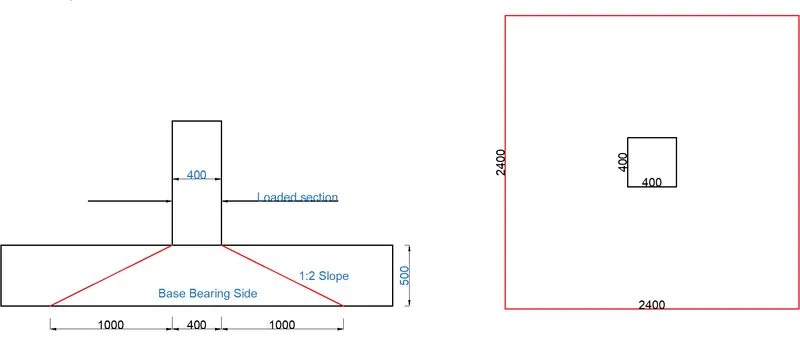
`sqrt (2400/400)` `<=` 2.
0.122 < 2.
Here, the bearing stress is as per IS-456-2000 clause 34.4
3. Initial depth of footing calculation :
- Permissible bearing Stress 0.45 x Fck = 11.25 N/`mm^2`.
Permissible bearing stress multiplied with area factor 11.25 x 2 = 22.50 N/`mm^2`
- Actual bearing stress at Column base
(2000 `xx` 1000)/(400 `xx` 400) = 12.5 N/`mm^2`
12.5 N/`mm^2` actual stress is less than the permissible 22.5 N/`mm^2`. Hence Okay.
We can proceed with 500mm depth footing for further design checks.
If we assume 50mm cover for footing, the effective depth (d) shall be taken as 450 mm.
4. Flexural reinforcement calculation :
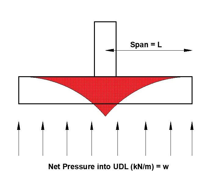
- Conversion of net pressure into Uniformly distributed Load.
UDL = `P_n` `xx` Footing area.
UDL = 195.3 `xx` 3.2
UDL = 625 kN/m.
- Bending Moment due to UDL over a cantilever section
M = `(wL^2)/2`.
M = `(652(1.6)^2)/2` .
M = 800 kNm.
- Reinforcement Calculation as per IS-456-2000 Annex-G
`M_u = 0.87 f_y A_st d (1 - (A_st f_y)/(b d f_ck))`
Assume Fy = 500 N/`mm^2`, in result Ast required = 4350 `mm^2`.
If we provide 16mm dia rebar at 125 mm spacing, the actual rebar provided = 3200/125 `xx` 201.
Ast provided = 5146 `mm^2`.
5. One Way shear check :
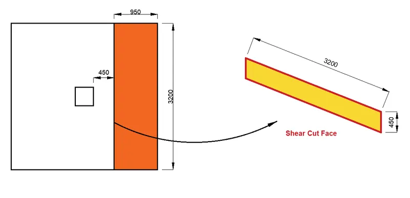
- Shear force in the one way shaded area.
`tau`= 0.95 `xx` 3.2 `xx` 195.3
`tau` = 593.7 kN
- Design shear stress at One way cut face
`tau_v` = (593.7 `xx` 1000)/(3200 `xx` 450)
`tau_v` = 0.412 N/`mm^2`.
- Shear stress capacity of section as per IS-456-2000 Table-19 (include rebar) = 0.425 N/`mm^2`.
- Design shear stress is less than shear capacity.
Hence Okay.
6. Two way shear check :
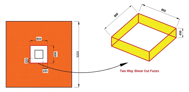
- Shear force in the two way shaded area.
`tau` = (3.2 `xx` 3.2) - (0.85 `xx` 0.85) `xx` 195.3
`tau` = 1859 kN.
- Design shear stress at Two way cut face
`tau_v` = (1859 `xx` 1000)/(3400 `xx` 450)
`tau_v` = 1.215 N/`mm^2`.
- Shear stress capacity of section as per IS-456-2000 clause 31.6.3.1 = 0.25 `xx` `sqrt`Fck
Shear stress capacity= 1.25 N/`mm^2`.
- Design shear stress is less than shear capacity.
Hence Okay.