Design of Shallow Foundation (Isolated Footings)
AIM:
To know the general design procedure of spread footing with manual calculations
To understand how the inputs can be colloborated and arrived as data for calculations
INTRODUCTION:
The spread footing behaves like an inverted cantilever with loads applied in the upward direc-tion. As a rule, a spread footing is a quite rigid element therefore, the applied soil stresses are almost linear and in case of a symmetric (with respect to the pedestal) footing, they are or-thogonal. These soil pressures constitutes the loads carried by the footing which behaves like a slab and is deformed.Soil pressures and deformation of an isolated spread footing.
PROCEDURE:
Given:
Column size = 400 x 400 mm
SBC = 150mm^2
Compression axial load=2000KN
`f_(ck)`=M25
Steps to design a square footing:
1. Size of footing
2. Net upward pressure
3. Bending moment
4. Depth of footing
5. Reinforcement
6. One way and two way shear
PROCEDURE:
STEP 1:
Size of footing
Load on column= 2000kN
Add 10% of column axial load for footing = 10%(2000)
2000+200=2200kN
Area of footing
Area of footing=Load on footing/Safe bearing capacity
=2200/150
=14.66m2
`root`14.66 =3.82
->4mx4m
Therefore provided area=16m2
STEP 2:
Net upward pressure:
`sigma`= Factored load/Area
=1.5xTotal load on footing/area
=1.5x2200/4x4
=206.25kN/m2
STEP 3:
Bending Moment:
At the critical section of the footing face of the column from the edge of footing
(4000/2)-(400/2)=1800 mm
Therefore load on critical section = `sigma` x breadth of footing
=206.25x4
Load=825kN/m
So,the bending moment=wl^2/2
=(825x1.8^2)/2
=1336.5kN-m
STEP 4:
Depth of footing
`M_(u)`=0.138`f_(ck)bd^2`
=0.138x25x4000xd^2
1336.5x10^6= 0.138x25x4000xd^2
d=311.20mm
By the thumb rule we can take 2-2.5 times higher value of d for shear check
Therefore,
d=778mm
D=d+effective cover+bar dia+half of bar dia
=778+50+20+10(Assuming bar dia as 20mm)
D= 860mm
STEP 5:
Reinforcement:
Bending moment = 1336.5 x10^6
Percentage of reinforcement,
`P_(t) = 50 (f_(ck)/f_(y))(1-root'4.6`x13336.5x10^6/25x4000x778^2)
Therefore
`P_(t) = 0.1570%`
Area of steel =`(P_(t)/100)astbd`
=(0.157/100)x4000x778
`A_(st)` = 4885mm^2
No of bars
Take 20mm bar
No of bar = 4885/314.5
=15.55=16 no
Provide 16 nos of 20mm bar
`A_(st)` provided= 16x314.5
=5032mm^2
Therefore
`A_(st)>A_(st)` provided
4885>5032
Hence OK
STEP 6:
Check for clear spacing between bars
As per IS 456-table 15, for Fe 415, the clear spacing between the bars should be less than 180 mm
c/c spacing = (4000-50-50-10-10)/(no. of bars-1)
=258.66mm
Therefore,
Clear spacing = 242.5 - half of dia - half of dia bar
= 242.5-10-10
Clear spacing = 238mm
As per IS code value our value is greater so obtained clear spacing is greater than IS code value
In order the min value reduced the bar size
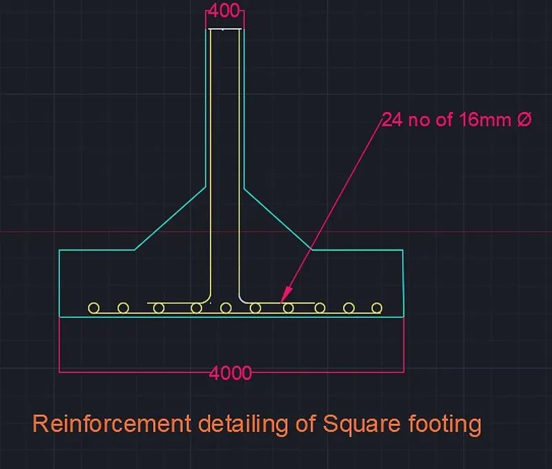
Take 16mm bar=4885/200.96
Therefore
No of bars = 24.3
=24
c/c spacing = (4000-50-50-8-8)/(No of bars-1)
=168.89
Clear spacing = 168.86 - 8 - 8
=152.86mm
So, clear spacing 152.86<180
Hence OK
STEP 7:
Check for one way shear:
One way shear at the critical section for one way shear at the distance d from face of the column
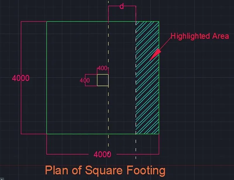
`V_(u)`=Upward pressure x Area of highlighted section
=206.25x4xArea of highlighted section
Area of highlighted section=(4000/2)-(400/2)-778
=1.022
Now,
`V_(u)` =206.25x4x1.022
`V_(u)`=843.15kN
Nominal stress:
`tau_(v)`= `V_(u)`/bd
=(843.15x10^3)/(4000x778)
`tau_(v)`=0.27 N/m
Now compare
`tau_(v)` and `tau_(c)`
For the `tau_(c)`value given by IS 456,Table 19
`P_(t)`provided =(100 `A_(st)`/bd)
`A_(st)`=24 no of 16mm dia
=4823mm^2
Therefore,
`P_(t)`=(100x4823)/(4000x778)
=0.1549
From table 19 of IS 456
(100 `A_(st)`/bd) value should be `le`0.28N/mm^2
`tau_(v)` <`tau_(c)`
=0.15<0.28
Hence OK
STEP 8:
Check for two way shear
At peripheral d/2 distance from face of the column
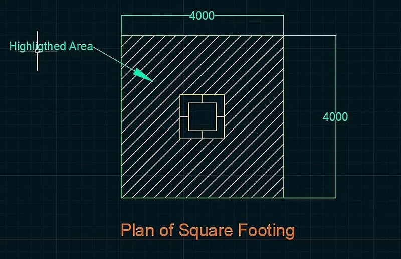
Area of highlighted section = 400+(778/2)+(778/2)= 1178 mm^2
Therefore area = 4^2 - 1.178^2
=14.6123mm^2
`V_(u)`=Upward pressure x area of highlighted section
=206.25x14.6123
`V_(u)`=3013.79kN
`tau_(v)=V_(u)/`bd
Peripheral length=4x1178
b=4712mm
`tau_(v)`=(3013.79x10^3)/(4712x778)
`tau_(v)`=0.8221N/mm^2
Compare,
`tau_(v)` and `tau_(v)`
For two way shear
`tau_(c)`=`K_(s) ast tau_(c)`
For `tau_(c)` value taken from IS 456-2000 page number 58
`K_(s)`=1(for square column)
`tau_(c)`=0.25 `root``f_(ck)`
=1.25N/mm^2
Therefore
`tau_(c)`=`K_(s) ast tau_(c)`
=1x1.25
`tau_(c)`=1.25N/mm^2
Therefore
`tau_(v)`<`tau_(c)`
0.8221<1.25
Hence OK
Reinforcement detailing drawing