Design of Shallow Foundation (Isolated Footings)
AIM
Designing a footing for a column size of 400*400
INTRODUCTION
- The footing is a structural member that safely transmits the load of the upper building to the ground, and is the first construction member of the building.
- Loads from the structure are transferred to the soil or rock under the structure via footings and other foundation elements
- The kind of soil and the foundation pad , affect how much pressure the soil exrts on a footing
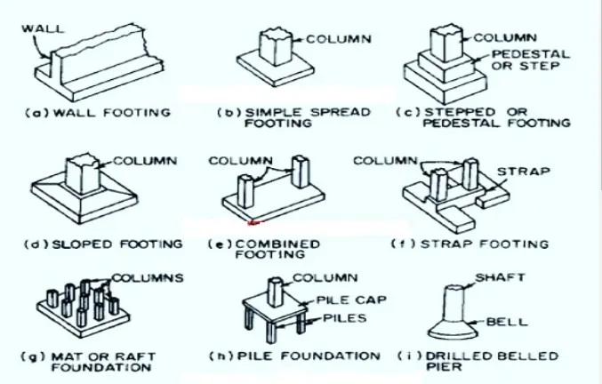
- The most typical forms of footing are
- Strip or wall footing
- Spread footing
- Stepped footing
- Tapered footing
- Pile cap
- Combined footing
- Mat or raft footing
GIVEN DATA
- Column size = 400mm*400mm
- Compression axial load (1.5DL+1.5LL) = 200kN-factored load
- Safe bearing capacity of soil at a depth of 2m below EGL = 150kN/m2
- Assuming the self -weight of footing and soil above it as 10% load
- Grade of concrete= 25kN/m
- Assuming Fy =500N/mm2
STEPS TO DESIGN FOOTING
- Gross soil pressure for footing area
- Net soil pressure for flexure and shear design
- Depth of footing
- Flexural reinforcement
- One way shear
- Two way shear
PROCEDURE
Step:1
- GROSS SOIL PRESSURE AND FOOTING AREA
- Unfactured load with surcharge+self weight of footing/allowable soil pressure
=(2000/1.5*1.1)/150
= 9.82m^2
Assuming we have square footing =3.12 side footing
consider 3.2m sided isolated footing
Step:2
- NET SOIL PRESSURE AND INITIAL FOOTING DEPTH
- Factored load/ actual area of footing
= 2000/(3.2*3.2)
=Pn= 195.3kN/m2
Assume the depth of the footing 500mm
check it for bearing stress as per IS 456-2000,clause 34.4
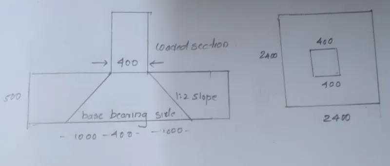
Therefore,
Permissible bearing stress 0,45*fck=0.45*25=11.25 N/mm^2
Permissible bearing stress multiplied by the area factor of 2 = 11.25*2 =22.5 N/mm^2
Actual bearing stresses at the column base of the footing
2000*1000/400*400 = 12.5N/mm^2
Actual bearing stress
12.5<22.5
Hence 500mm depth is okay and provide 50mm for cover
D=500mm
d'=50mm
d = D-d'
Effective depth (d)= 450mm
Step:3
- FLEXURAL REINFORCEMENT
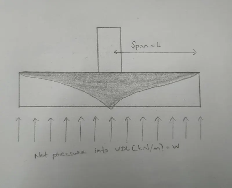
Conversion of netpressure into UDL
= 195.3*3.2 = 625kN/m
Bending moment due to UDL over cantilever section
= WL^2/2
M= 625*1.6*1.6/2
M = 800 kN-m
Reinforcement calculation as per IS -456:200 , Annuex G
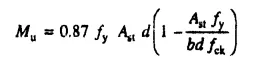
Mu = 800 kN-m
D= 450mm
fy = 500N/mm^2
b = 400 mm
fck = 20 N/mm^2
Ast = 4350mm^2
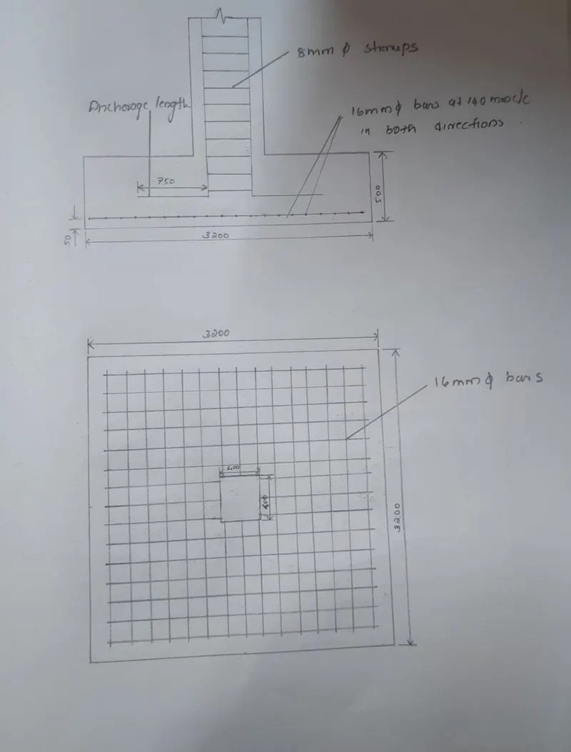
If we provide 16mm dia rebar at 125mm spacing actual rebar provided = 3200/125*202
Ast provided = 5146 mm^2
Step:4
- ONE WAY SHEAR STRESS CHECK
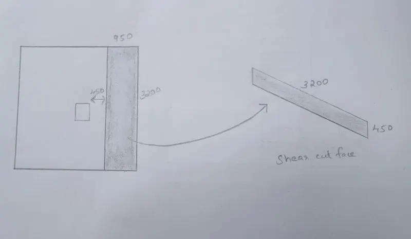
Shear force in one way shaded area
= 0.95*3.2*195.3 = 593.7kN
Design shear stress at one way cut face
T = 593.7*1000/(3200*450) = 0.412N/mm^2
Design shear stress is less than shear capacity
Hence okay
Step:5
- TWO WAY SHEAR STRESS CHECK
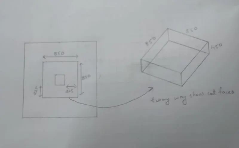
Shear force in two way shaded area
V = (3.2*3.2)-(0.85*0.85)*195.6
= 1859kN
Design shear stress at any two cut face
T = 1859*1000/(3400*450)=1.215 N/mm^2
Shear stress capacity of section as per IS -456
-2000 clause 31.6.3.1 = 0,25 * fck = 1.25 N/mm^2
Design shear stress is less than shear capacity
Hence okay.
RESULT
- Provide a 3.2m*3.2m footing with a depth of 500mm
- Provide reinforcement pf 20 mm dia bars in both directions
- Provide anchorage for column and footing at 750mm
----------------------------------------------------------------------------------------------------------------------------------------