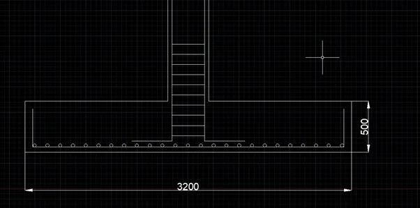
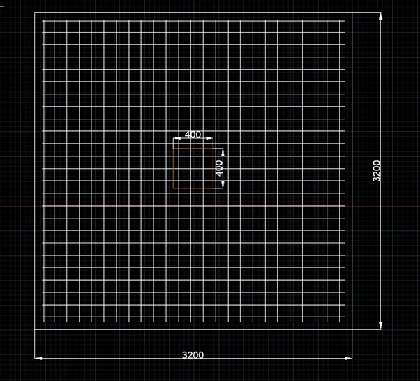
Design of Shallow Foundation (Isolated Footings)
1.
Aim
To design a Square footing for a column size 400 x 400.
Given Data
Axial compression Load of 1.5DL + 1.5 LL is 2000KN.
Safe Bearing Capacity is 150KN/m2 @ 2m Depth
Concrete M25
To check
If the gross bearing pressure is within the safe bearing capacity.
To provide sufficient depth and Longitudinal Reinforcement.
Sufficient Anchorage for columns inside the footing.
Check whether the bearing pressure at column footing is within 0.45 times the maximum concrete compressive strength.
Procedure & Result
To Calculate Gross Soil Pressure
- Unfactored load with surcharge + Self weigh of Footing / Allowable soil Pressure
Consider Surcharge and Self weight is 10% of the total load.
= (2000 / 1.5 x 1.1 ) / 150
Area of footing = 9.78m2
We have taken square footing so the Length and width are 3.12m
Let us consider 3.2 m footing.
Net Soil Pressure.
Net soil Pressure = factored Load / Actual Area of Footing
= 2000 / (3.2 x 3.2)
= 1958.3 KN/m2
Assuming the depth of footing as 500mm and checking with the bearing stress as per IS 456 2000 Clause 34.4
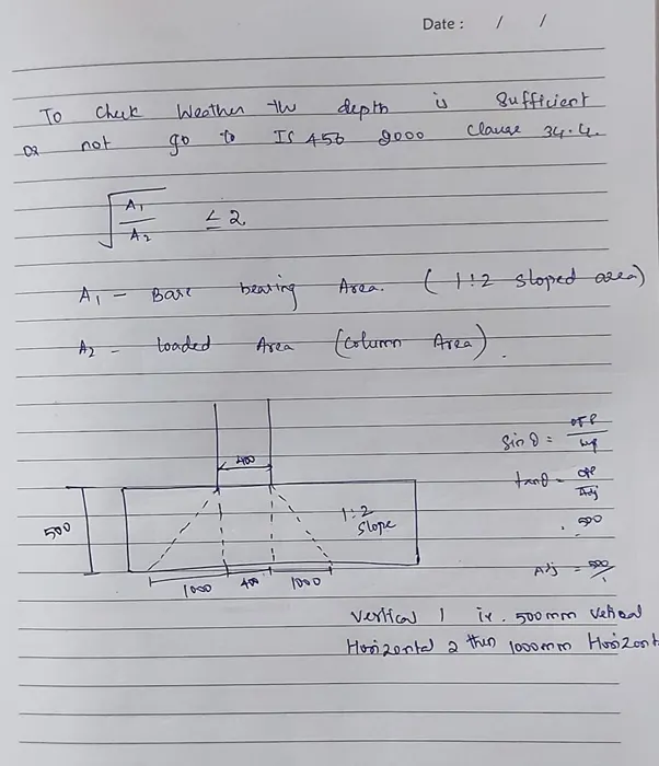
Maximum area to be used is not exceed 2
Permissible bearing stress = 0.45 x Fck = 0.45 x 25 = 11.25 N/mm2
Permissible bearing stress multiplied with area factor = 11.25 x 2
= 22.5N/mm2
Actual bearing stress at column base.
= Load / Area
= 2000 / (400 x 400)
= 12.5N/mm2
12.5 N/mm2 actual stress is less than permissible 22.5N/mm2. Hence Okay.
We can proceed with 500mm depth. And the effective depth is 450mm
Flexural Reinforcement
To convert net pressure in to UDL is = 195.3 x 3.2
= 625 KN/m
Bending moment due to UDL over a cantilever is
= wL2 / 2, Where L is half the length of footing.
= ( 625 x 1.6 x 1.6 ) / 2
= 800KNm
To calculate Reinforcement, as per IS 456 2000 Annex G
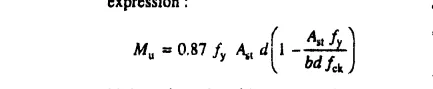
Here fy = 500 N/mm2
d = 450mm
b = 3.2 m
fck = 25 N/mm2
By substituting all the values and finding the Ast value
Ast required is 4350m2
If we provide 16mm dia at 150mm center to center the Ast provided will be 4220 mm2 which is less than required.
So increase decrease the spacing to increase the Ast.
If we provide 16mm dia at 125mm centre to centre the Ast is 5024mm2 which is higher than required.
Hence ok.
One Way Shear
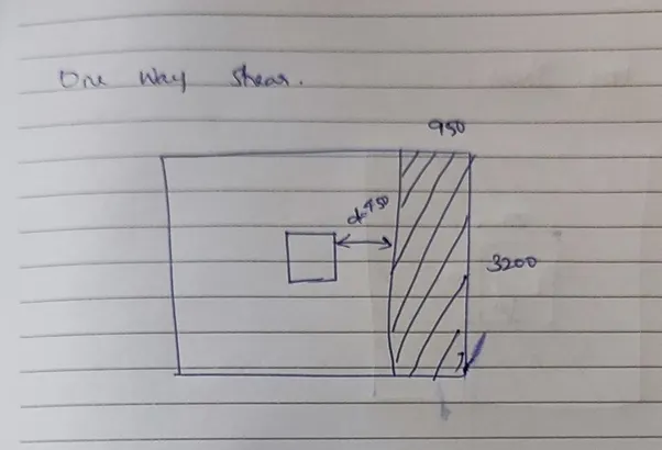
Shear force in one way Shaded area = Area x Soil Pressure
= 0.95 x 3.2 x 195.3
= 593.7KN
Design Shear stress at one way cut Tv = Shear force x Cut section area
= 593.7 / (3200 x 450)
= 0.412N/mm2
Shear stress Capacity as per IS 456 2000 of Table 19 is = 0.425N/mm2
100Ast / bd = 0.348
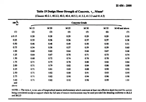
The designed shear is less than the shear capacity. Hence one-way shear is Ok.
Two Way shear
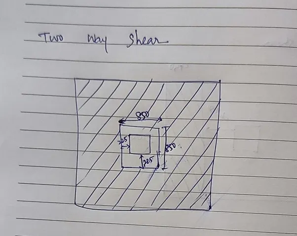
Shear force in two way shear is = Net Pressure x (Shaded area)
= 195.3 x (3.2 x3.2) – (0.85 x0.85)
= 1859 KN
Design Shear stress at Two way Cut surface = Shear force in shaded area x Area of suct surface
= 1859 x 1000 / (850+850+850+850 x 450)
= 1.215 N/mm2
Shear stress capacity as per IS 456 2000 Clause 31.6.3.1
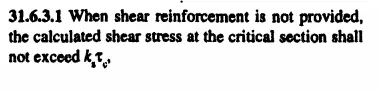
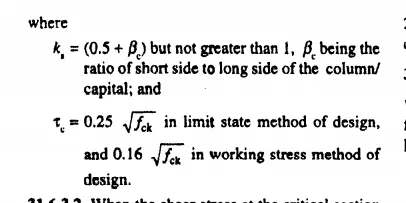
Here Kc is 1
Shear = 0.25 sqroot 25
Hence shear stress capacity is = 1.25N/mm2
Design Shear Stress is less than shear capacity. Hence Ok.
Reinforcement Details
Development Length = 50 x Dia