Design of Shallow Foundation (Isolated Footings)
AIM
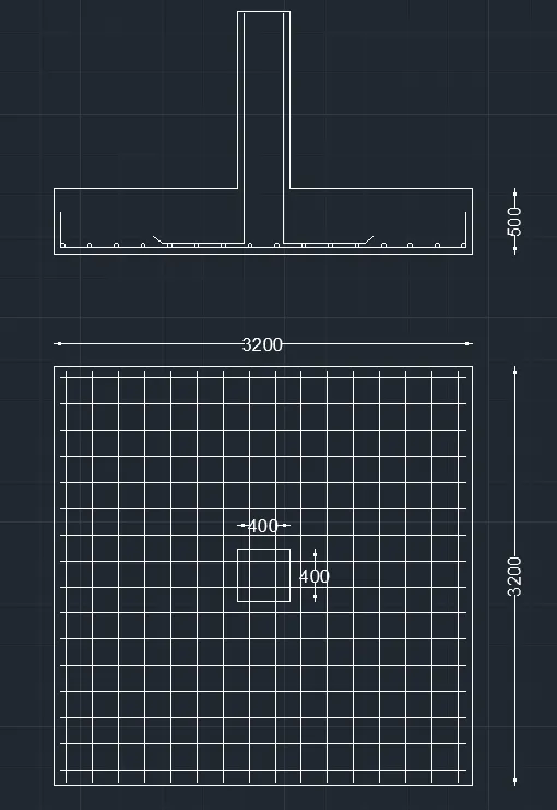
To design a square footing for a column size of 400x400 and sketch the footing.
INTRODUCTION
Footings and other foundation units transfer loads from the structure to the soil or rock supporting the structure. Because the soil is generally much weaker than the concrete columns and walls that must be supported, the contact area between the soil and the footing is much larger than that between the supported member and the footing.
Shallow/spread footings are the most widely used type among all foundations because they are usually more economical. Construction of footings requires a least amount of equipment and skill and no heavy or special equipment is necessary.
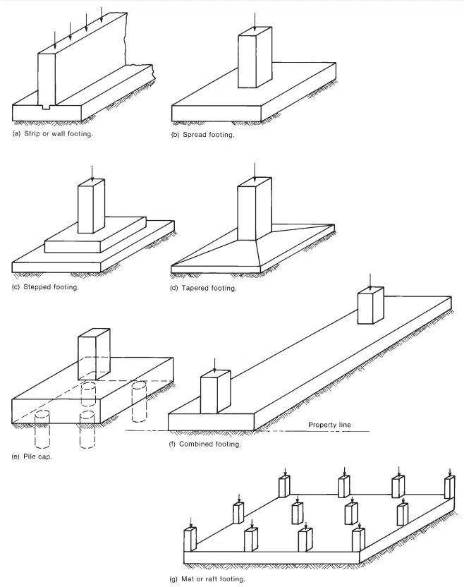
Most common types of footings used are:
- Strip or wall footing
- Spread footing
- Stepped footing
- Tapered footing
- Pile cap
- Combined footing
- Mat or raft footing
PROCEDURE
i) Calculation of gross soil pressure for footing area
- Gross soil pressure = Unfactored load with surcharge + self weight of footing/allowable soil pressure
- Gross soil pressure = (2000/1.5 x 1.1)/150 = 9.78 m2 (Assuming square footing)
- Side footing = √9.78 = 3.12 m
- Consider, 3.2 m sided isolated footing
ii) Calculation of Net soil pressure for flexure and shear design
- Net soil pressure = Factored load/actual area of footing
- Pn = 2000x1000/ (3.2x3.2)
- Pn = 195.3 kN/m2
iii) Initial depth of footing calculation
- Assume depth of footing 500 mm and checking it for bearing stress as per 1S-456-2000 clause 34.4
- √(footing base bearing area/loaded area) ≤ 2
- Permissible bearing stress = 0.45 x Fck = 11.25 N/mm2
- Permissible bearing stress multiplied with area factor = 11.25 x 2 = 22.5 N/mm2
- Actual bearing stress at column base = (2000x1000)/(400x400) = 12.5 N/mm2
|
12.5 N/mm2 actual stress is less than permissible 22.5 N/mm2. Hence Okay. We can proceed with 500mm depth footing for further design checks. If we assume 50mm cover for footing, the effective depth (d) shall be taken as 450 mm. |
iv) Flexural reinforcement calculation
- Conversion of net pressure into uniformly distributed load = 195.3 x 3.2 = 625 kN/m
- Bending moment due to UDL over a cantilever section, M = wL2/2 = 625x1.6x1.6/2 = 800 kNm
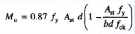
- Reinforcement calculation as per IS-456-2000 Annex-G
|
If we provide 16 mm dia. rebar at 125 mm spacing, Ast provided = 3200/125 x 201 Ast provided = 5146 mm2 |
v) One way shear check
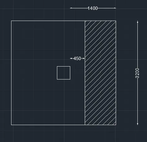
- Shear force in the one way shaded area = 0.95 x 3.2 x 195.3 = 593.7 kN
- Design shear stress at One way cut face, τv = 593.7x1000/ (3200x450) = 0.412 N/mm2
- Shear stress capacity of section as per IS-456-2000 Table-19 (include rebar) = 0.425 N/mm2
| Design shear stress 0.412 N/mm2 is less than shear capacity 0.425 N/mm2. Hence Okay |
vi) Two way shear check
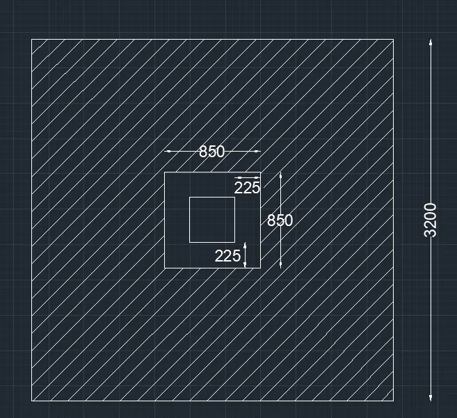
- Shear force in the two way shaded area = (3.2x3.2) - (0.85x0.85) x 195.3 = 1859 kN
- Design shear stress at Two way cut face, τv = 1859x1000 / (3400x450) = 1.215 N/mm2
- Shear stress capacity of section as per IS-456-2000 clause 31.6.3.1 = 0.25 x √Fck = 1.25 N/mm2
| Design shear stress 1.215 N/mm2 is less than shear capacity 1.25 N/mm2. Hence Okay |
vii) Sketch the footing
- Using AutoCAD, footing details is shown below
RESULT
A square footing column of size 400x400 is designed and is sketched in AutoCAD.