Design of Shallow Foundation (Isolated Footings)
Design a square footing for a column size of 400x400. The compression axial load for the load combination of (1.5 DL + 1.5 LL) is 2000 kN. The safe soil bearing capacity is 150 kN/m2 at a depth of 2 metres below E.G.L. Participants are free to go for either a tapered or stepped footing. Besides the total axial load, also account for the self-weight of the footing and soil above it. Assume M25 concrete grade. Do the following checks:
· If the gross bearing pressure under the footing is within the safe bearing capacity
· Provide sufficient depth and longitudinal steel for resisting bending and shear
· Sufficient anchorage for column steel into the footing
· If the bearing pressure at the column-footing joint is within 0.45 times the maximum concrete compressive strength
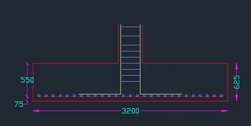
Provide a simple sketch showing the size of the footing, maximum and minimum depth of the section, flexural reinforcement in both directions and anchorage of column steel.
AIM
To design a square footing for the column size of 400x400 mm2. And to check whether the gross bearing pressure of the footing is within the safe bearing capacity. And to provide sufficient depth and the longitudinal steel for the resisting bending and shear and to also check the sufficient anchorage for the column steel into the footing.
PROCEDURE
Given Data:
Size of column = 400mm x 400 mm2
Factored load due to the column = 2000kN
SBC at the site = 150kN/m2
Concrete grade = M25
Steel grade = Fe415
Determining the size of footing
To find the size of the footing, we have the expression
P = F/A
Where,
P: soil pressure
F: unfactored load of column + self-weight of footing and surcharge pressure
A: Area of footing
Unfactored load due to column = Factored load/1.5
Unfactored load due to column = 2000/1.5 = 1333.33 kN
Assuming the self-weight of the footing as 10% of the total axial load
Therefore, self-weight of footing = 0.1 x 2000 = 200 kN
Hence the total unfactored load on the footing slab = 1333.33+ 200= 1533.33 kN
Substituting the above values in the formula, we get
A = F/P = 1533.33/150 = 10.22 m2
Width of footing = √A = 3.19 = 3.20m
And since we are adopting a square footing, the footing length would also be the same.
B = L = 3.20 m
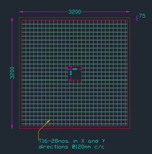
Therefore the size of the footing = 3.20 m x 3.20 m
CALCULATING THE NET UPWARD PRESSURE (PO)
The expression for the net upward pressure is as follows. Also this time, the total factored axial load plus self-weight of the footing and surcharge pressure shall be considered.
PO = W/B2 = 2200 / (3.2)2 = 214.84 kN/m2
DETERMINING THE EFFECTIVE DEPTH OF FOOTING BASED ON THE MAXIMUM BENDING MOMENT
The maximum bending moment for footings is given by the following expression,
M = Po x B/8 x (B-b)2
Here,
b is the column width
Substituting the values we get
M = 673.74 kNm
The ultimate moment
Mu = 1.5 x M = 1.5 x 673.74 = 1010.61 kNm
Also, Mu = 0.138 fck B d2
Solving for d we get,
d = 302 mm
However, this depth is insufficient as the code states to carry the column confinement into the footing which roughly accounts for 300mm. Therefore we need to go for a higher effective depth value.
So, based on practice, we adopt 550mm as the effective depth of footing.
d = 550mm
Assuming 75mm cover, total depth of the footing, D = 550 + 75 = 625 mm
OBTAIN THE REQUIRED AREA OF STEEL BASED ON THE ULTIMATE MOMENT CALCULATED
The expression for Ast is as follows,
`A_(st)= frac{0.5f_(ck)}{f_y}(1-sqrt (1-frac{4.6M_u}{f_(ck)Bd^2) ]) Bd`
Where,
fck= 25
fy = 415
Mu = 1010.61x106 Nmm.
B = 3200 mm
d = 550 mm
Solving the above expression, we get
Ast = 5364.8 mm2
Now we need to provide the flexural reinforcement based on the Ast calculated which is done as follows:
So, adopting the 16mm dia bars (201mm2)
No. of bars required = Ast/area of 16mm dia bars = 5365/201 = 26.6 = 28 bars
28 x 201 = 5628>5365. Hence OK.
Spacing = B/no. of bars = 3200/28 = 114.28 = 115mm c/c.
Now, as we know the minimum Ast for footing as per the code is equal to 0.12% of the gross footing area.
Therefore, Pt required= (Ast/BD) x 100 = (5628/3200x625) x 100 = 0.28% > 0.12%. Hence OK.
CHECK FOR ONE-WAY SHEAR
The critical section for the one-way shear lies at a distance d from the face of the column.
So, the net shear force at the critical section for one-way shear is given by
`V= P_oB[1/2[B-d]-d]`
Where,
Po = 214.84 kN/m2
B = 3.20 m
d = 0.55 m
Solving for V, we get
Vu = 532.8 kN
Therefore, the nominal shear stress, (τv)
τv = Vu/Bd = 532.8 X 10³/3200x550 = 0.30 N/mm2
Now we need to calculate the τc value to see if our concrete section is capable of taking this nominal shear stress or not.
So, τc' = τc x k
Here,
τc shear strength of concrete section as per IS 456:2000 (TABLE 19)
k is taken as the unit value for section depth more than 300mm
So, from table 19 by interpolation, as we have provided Pt as 0.32%, we get
τc = 0.39 N/mm2
Therefore, τc > τv. Hence the section is safe for one-way shear.
CHECK FOR TWO-WAY SHEAR
The critical section for two-way shear is spread across the footing at a distance d/2 from the face of the column
So, the expression to calculate net shear force Vu for that particular section is given by:
`V= P_o[B^2-(b+d)^2]`
where
Po = 214.84 kN/m2
B = 3.20 m
d = 0.55 m
b = 0.4 m
Solving this, we get
Vu = 2006 kN
Therefore, nominal shear stress due to punching shear (τv),
τv = Vu/Bd = 2006 x 103 / 3200 x 550 = 1.14 N/mm2
Now, obtain the design shear strength based on two-way shear (Ks x τc)
Here,
Ks is a mathematical constant based on the L/B ratio of footing
Ks = 0.5 + βc (βc > L/B ratio)
Since we have adopted a square footing, βc = 1
Therefore, Ks = 0.5 + 1 = 1.5
However, the maximum Ks value shall not exceed 1 as per IS code
Therefore taking Ks = 1
Now, τc = 0.25√fck = 0.25√25 = 1.25
So, τc > τv. Hence our section is OK for the two-way shear as well.
Reinforcement Bars Placement Plan
Section of the Footing