Design of backdoor
AIM :
Design of the Hatchback car backdoor using Catia V5
OBJECTIVE :
To create the following components of the backdoor panel from the given styling surface.
- Inner panel,
- The upper outer panel,
- Outer lower panel with the
- Hinge reinforcement (left and right)
- Gas stay reinforcement (left and right)
- Latch reinforcement
Theory :
"Back Door" is a door or door system on the back end of a motor vehicle through which passengers can enter or depart the vehicle or cargo can be loaded or unloaded. It does not include:
(a) A trunk lid; or
(b) A door or window that is composed entirely of glazing material and whose latches and/or hinge systems are attached directly to the glazing material.
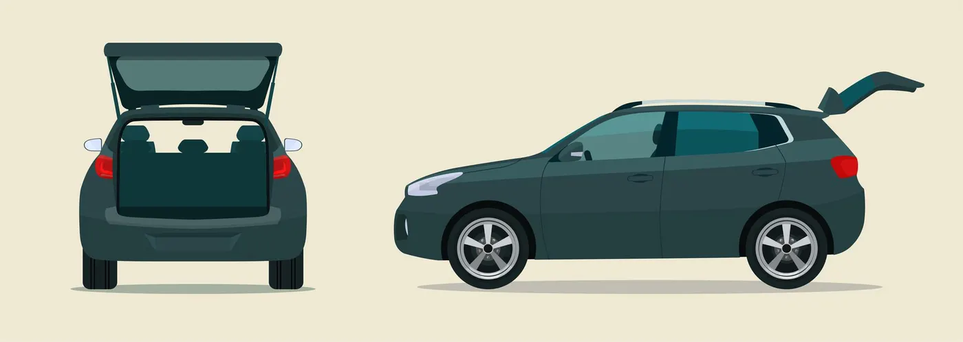
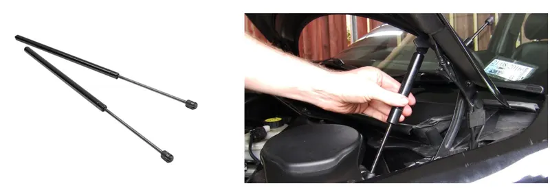
In most cars, these back doors are operated with the help of gas stay which in turn reduces the effort required to lift the door. Some luxury cars have a powered backdoor which in turn is driven by an electric motor. This kind of system is also called a powered trunk lid system hatchback or station wagons are sold as 3 doors or 5 doors models. In this case, the rear hatch is classified as a door this is because it enters the passenger compartment. The naming is mainly used in European countries. In the case of safety, the backdoor designed should meet the safety requirement of the rear collision.
The door or opening of a cargo area may be hinged at the top, side & bottom. If the door hinged in the bottom it is called a tailgate.
1.Top mounted
2.Side-mounted doors
3.Bottom type
Some terminologies :
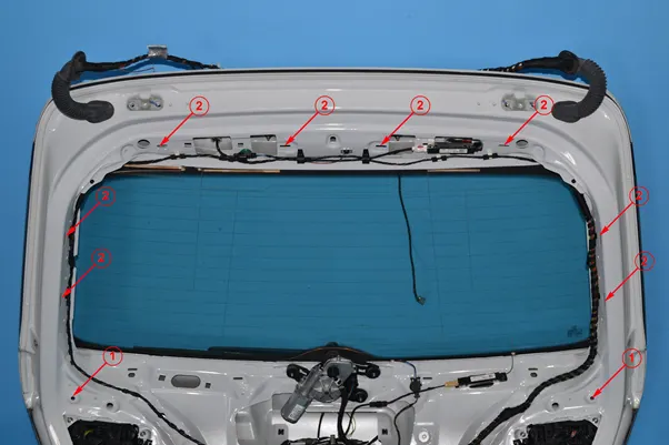
"Latch" is a device employed to maintain the door in a closed position relative to the vehicle body with provisions for deliberate release (or operation).
“Hinge” is a device used to position the door relative to the body structure and control the path of the door swing for passenger ingress and egress.
Gas Stay type backdoor is an ideal and most commonly used tailgate mechanism from lower segment car to luxury car segment. The ideal components of the tailgate consist of a hinge, door, gas stay, and some rubber beadings for sealing of the door.
PROCEDURE :
Outer panel :
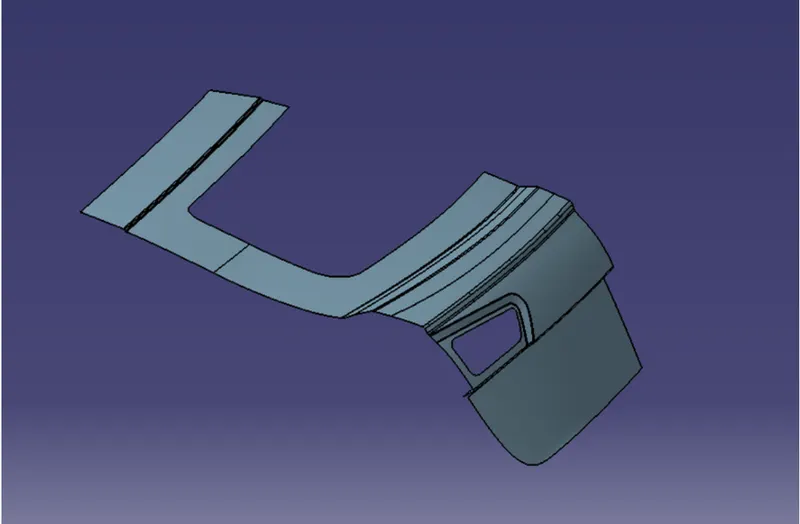
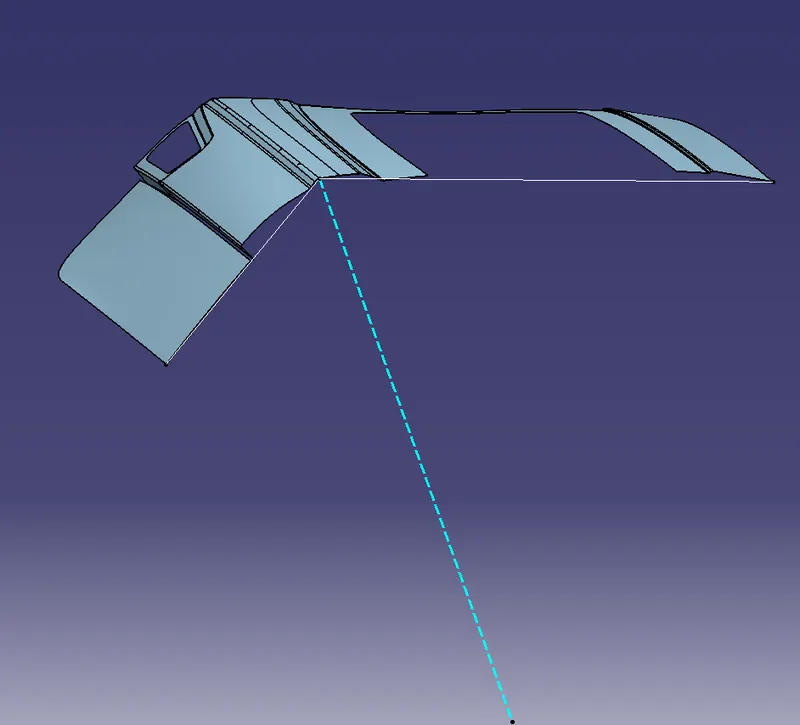
- The above class A styling surface is an input for designing the backdoor panel.
- The styling surface for the upper panel needs to be checked to have the proper connectivity with no gaps between them. As seen here the surfaces are not connected.
- To create the upper panel we use the trim, extrapolate and, blend tools to join the styling surfaces.
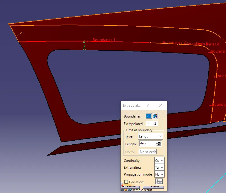
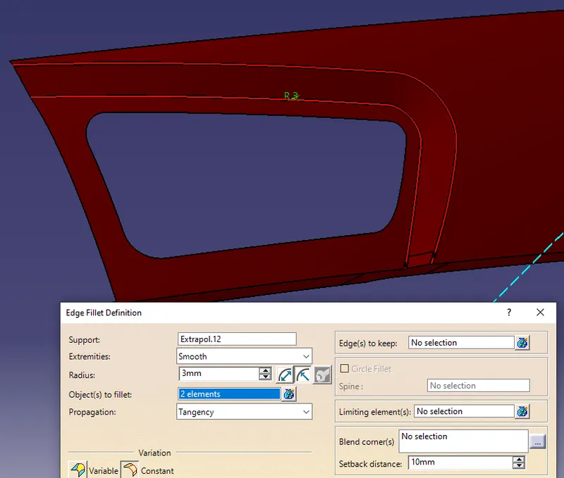
- Especially the tail lamp area is the surfaces were first extrapolated, trimmed, and then given the fillets.
Pic -Outer panel without hemming
Hemming :
Hemming in automotive manufacturing is a cold process of joining an inner and outer panel by folding the flanges of the outer panel onto the inner panel, permanently clamping the inner panel in place. This process is used in the manufacture of doors, hoods, and decklids and can be accomplished using a traditional press or with a robotically controlled roller.
The accuracy of the hemming operation is very important since it affects the appearance of the surface and surface quality. Material deformations, which occur during the hemming process, can lead to dimensional variations and other defects in parts. Typical hemming defects are splits or wrinkles in the flange, material overlaps in the corner areas, or material roll-in. This is why it is important to use simulation tools at the bottom, on the one hand, better understand the hemming process and, on the other hand, significantly reduce the number of “trial and error” loops during tryout and production.
Process :
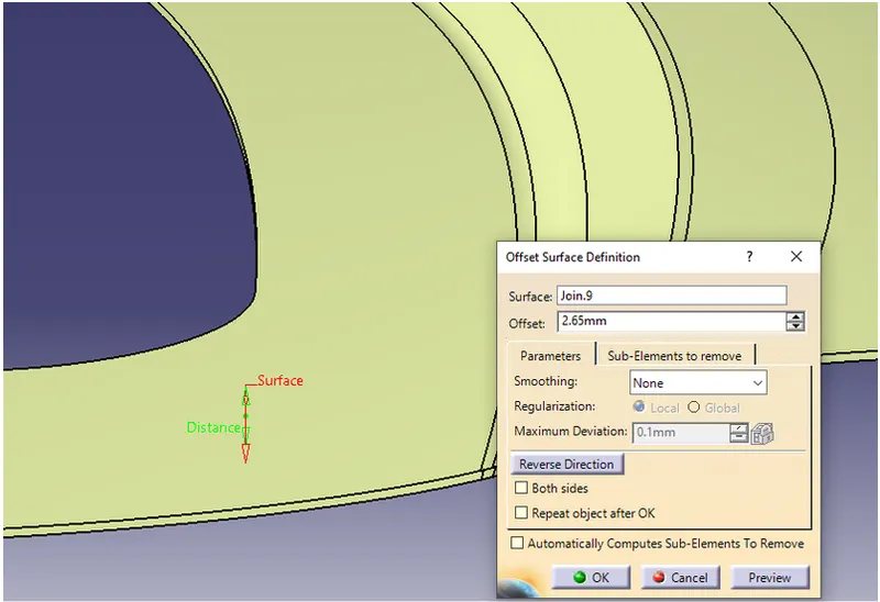
- To create the hemming first, extract and offset the outer panel by 2.65 mm (Outer panel Thickness- 0.75mm, Inner panel thickness 0.75 gap between Outer and Inner panel – 0.2mm, Hemming area bent region- 0.75mm, the gap between hem and Inner panel- 0.2mm)
- Now, use the parallel curve to split the surface to obtain the lower flange of the hemming.
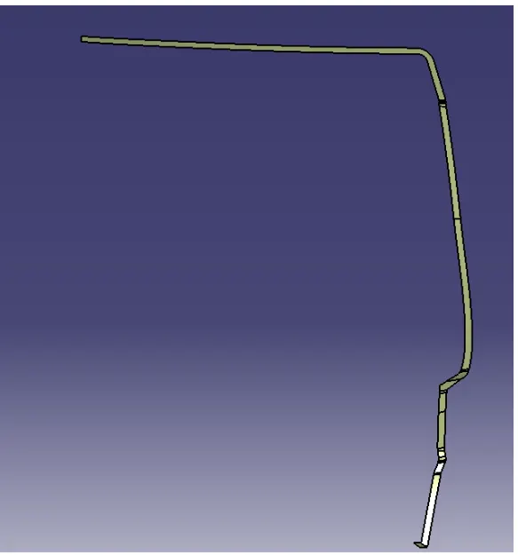
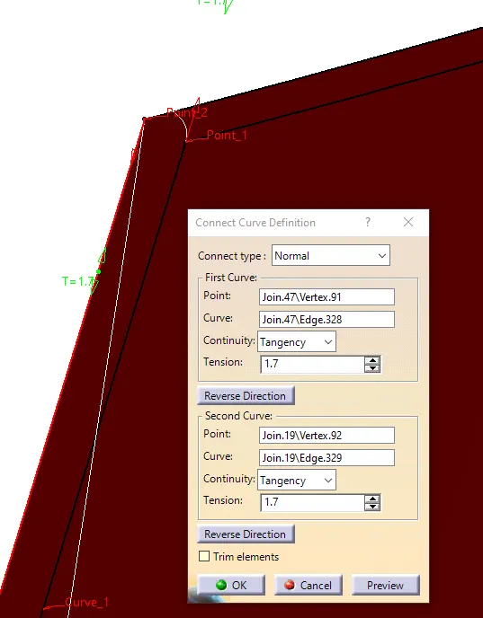
- Then use the connect curve to draw the curve for the hemming.
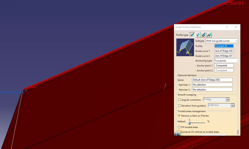
- Use the sweep using 2 guide curve to create the hem region for the outer panel.
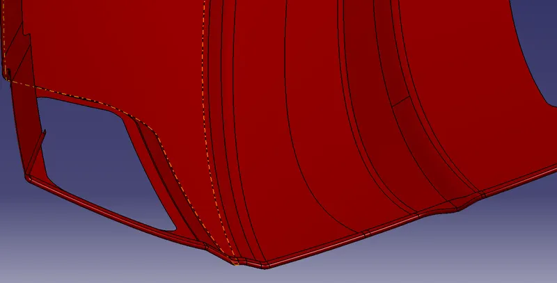
- Most of the regions are swept surface but in addition to that, some hemming surface was created using the blend and multisection tools.
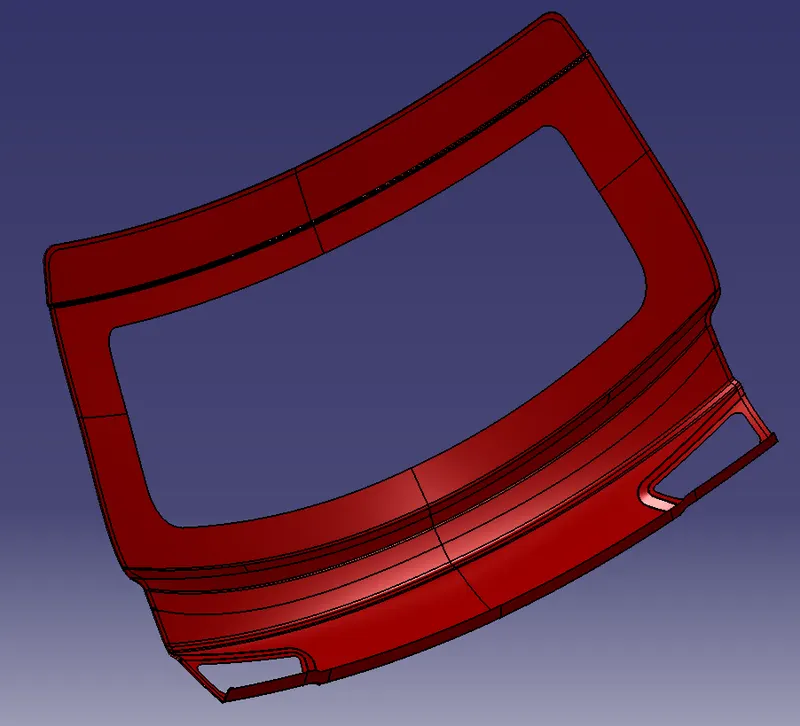
- All the surfaces are then joined avoiding any gaps followed by using symmetry to get the other side of the panel.
Note :
Certain improvement was made in the styling surface while creating the hemming since abrupt changes of the hem surfaces were causing problems in the thickening
Creating the tooling axis :
The tooling axis is created first, to make sure the part is producible in drawing operation and the other is to use this axis for the sweeping operation of the inner panel sidewalls.
- Click on the line option and select the Bisecting option.
- Draw 1 Line by selecting the point from the Vertex of the Upperside of the corner to the position where the declination starts. Click ok and the line is created.
- Now create the second line and follow the same procedure but from the lower surface. Click Ok and the line is created.
- Then draw a line using bisecting select line 1 and line 2 to get the final line.
- The line created is the main tooling Axis.
Lower outer panel :
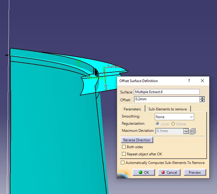
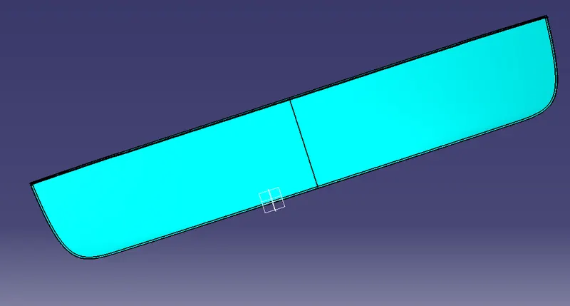
- Lower outer panel class a surface is offset to 0.2mm since the upper and lower will be joined by spot welding. So both the surfaces were offset to 0.2mm and extrapolated followed by trimming.
- A fillet of 3.5 mm is provided.
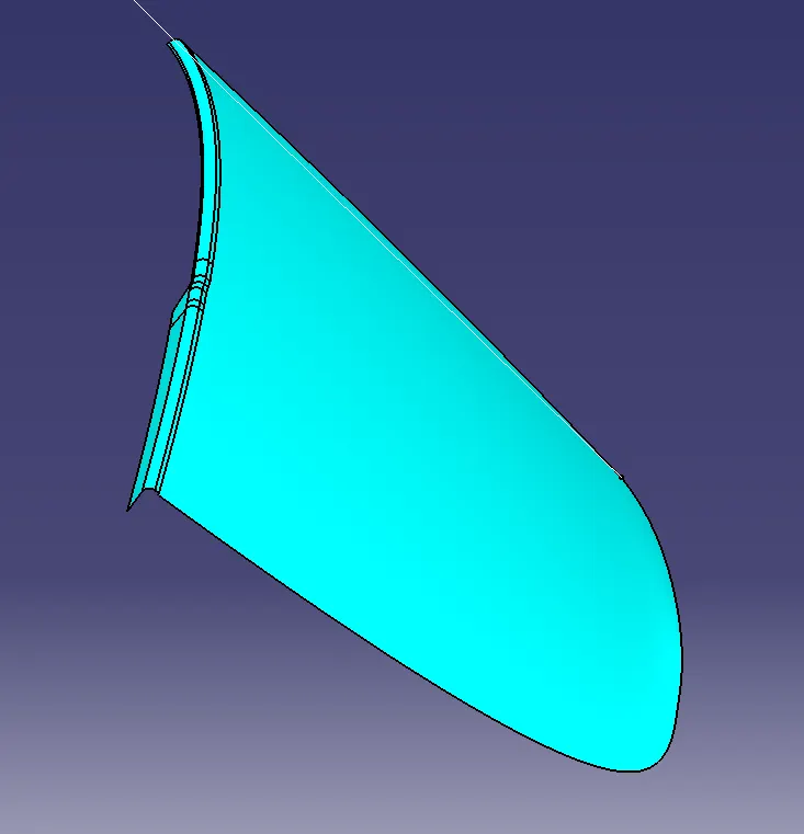
- For the hemming, the procedure followed for the upper panel is the same here. The surface is offset to 2.65mm( Outer panel Thickness- 0.75mm, Inner panel thickness 0.75 gap between Outer and Inner panel – 0.2mm, Hemming area bent region- 0.75mm, the gap between hem and Inner panel- 0.2mm)
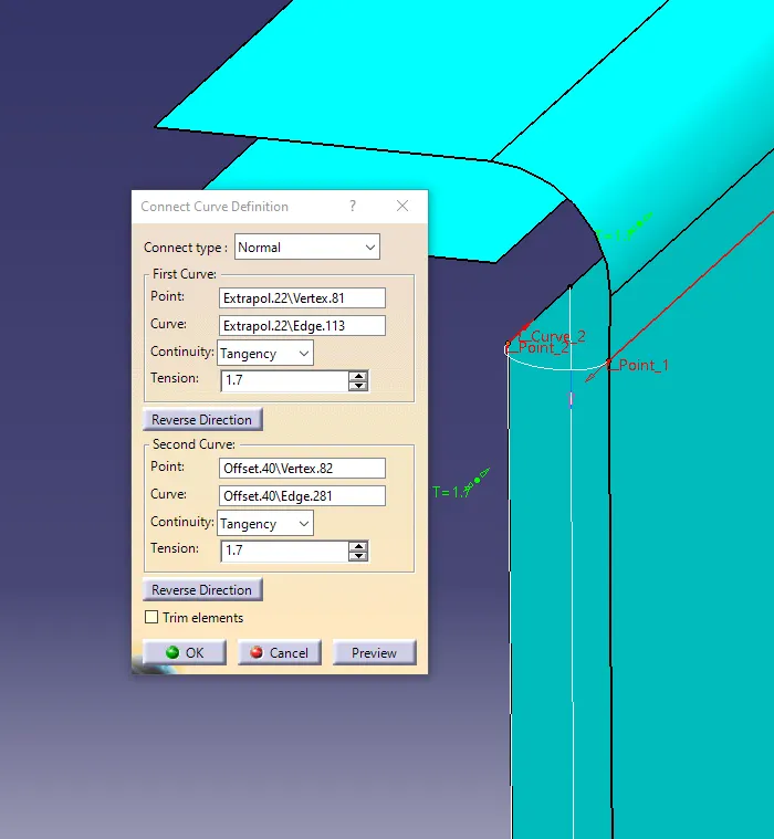
- Later, the hemmed surface curve is created using the connect curve with tangency value 1.7mm (this value is just the arbitrary value), and later on, the surface is created using the sweep using two guide curves.
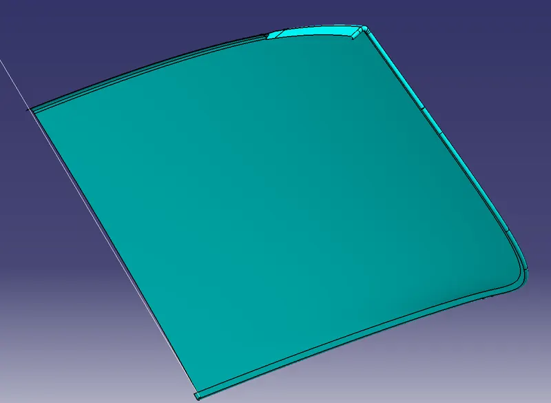
- Finally, the outer half is reflected to and joined to get the lower outer panel.
Inner panel :
- The inner panel is a single body, unlike the outer panel that has two parts as upper and lower.
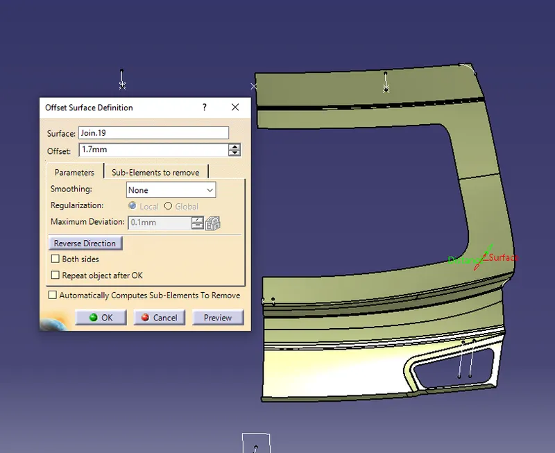
- For the inner panel, the outer panels are offset to the inner side by 1.7mm ( thickened outer panel 0.75mm, thickened inner panel 0.75mm, and 0.2mm gap.)Later on, the surface is again offset to 25mm downwards for the bottom flange of the panel.
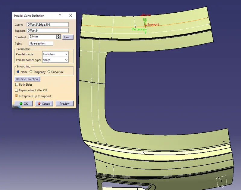
- Bottom flange width is taken here as 30mm. So for that parallel curve followed by split is used obtain the strip.
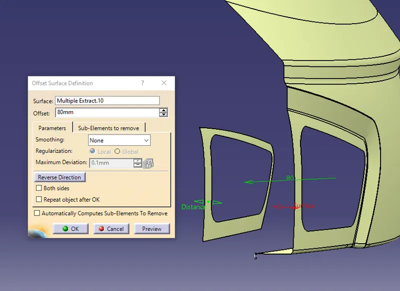
- The tail lamp part is offset to 80mm and untrimmed followed by splitting to have a continuous smooth aesthetic surface.
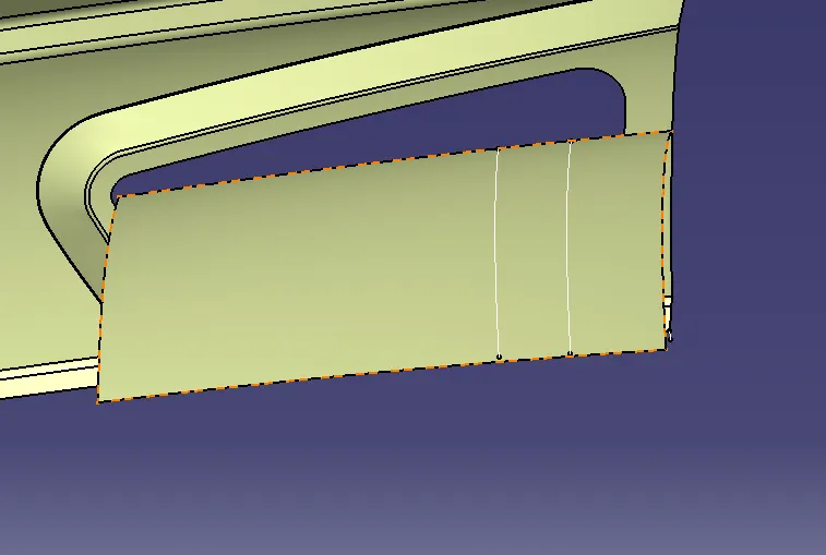
- After splitting, the small strips are connected by drawing the proper curve as the guide for the multisection surface.
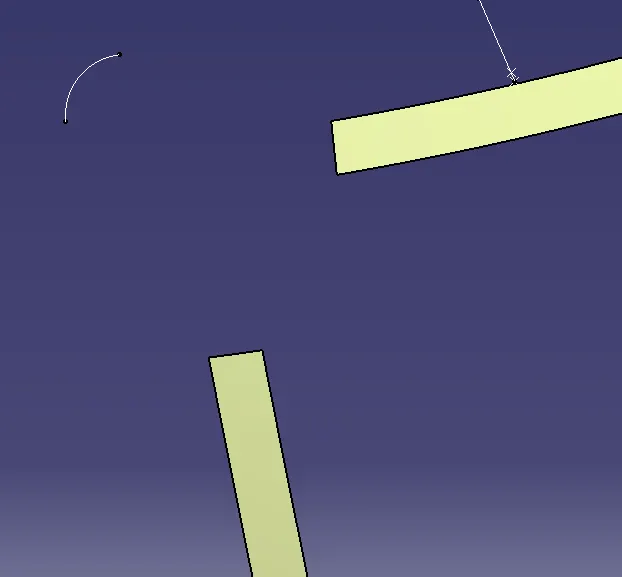
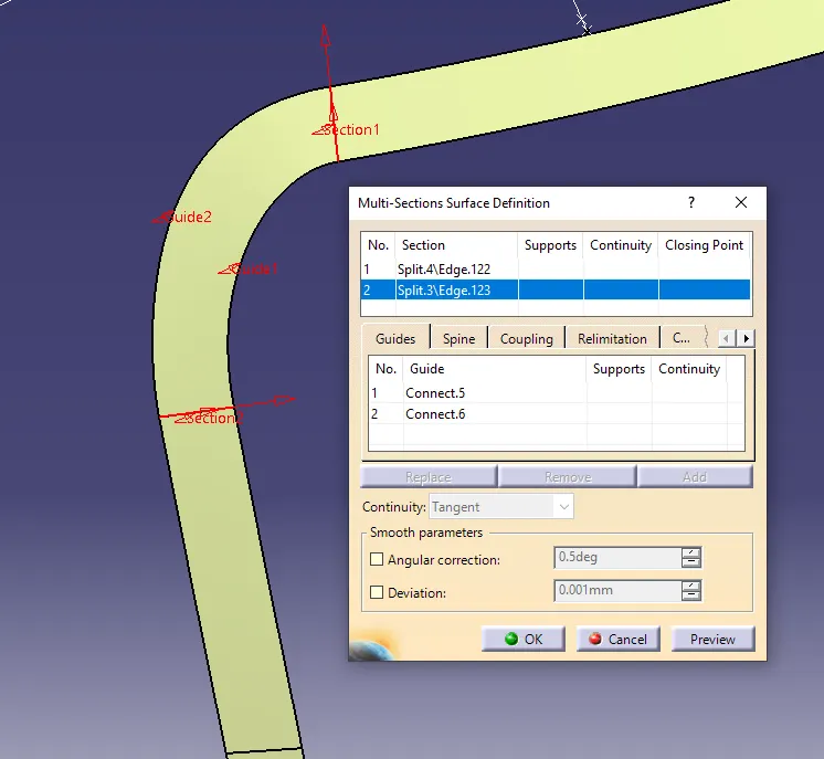
- All the small surfaces are joined to form the lower flange of the inner panel
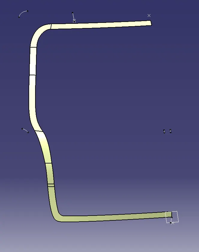
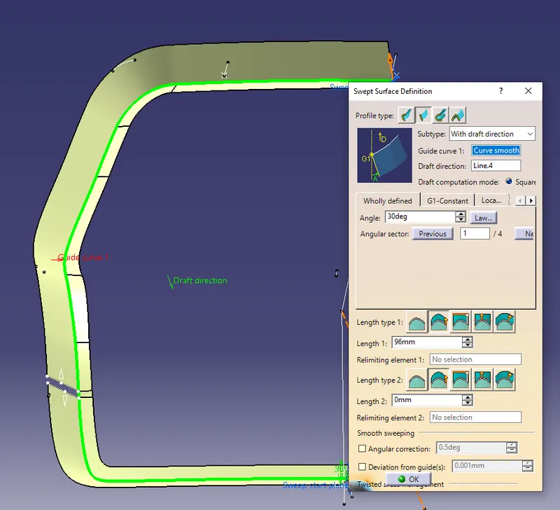
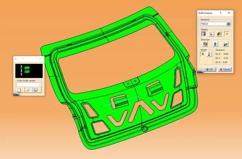
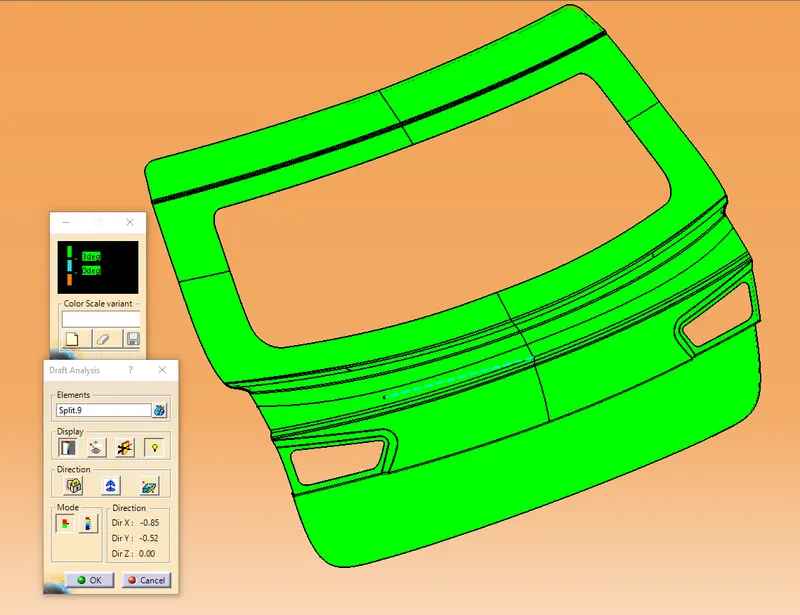
- Later on, both the side edges are swept along the tooling direction with the draft angle of 30 degrees (all the parts designed have to be producible).
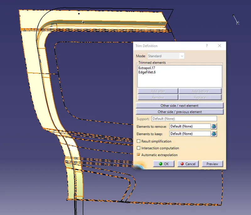
- Then, the swept surface is trimmed with the surface offset by 1.7mm from the parent surface.
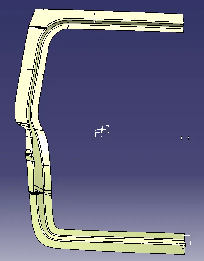
- The lower region surface of the inner panel is created using the multisection and then extrapolating and trimming. The corners were provided with the appropriate fillets.
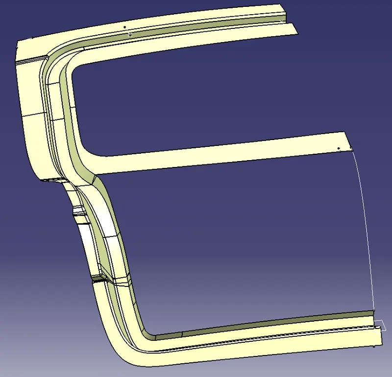
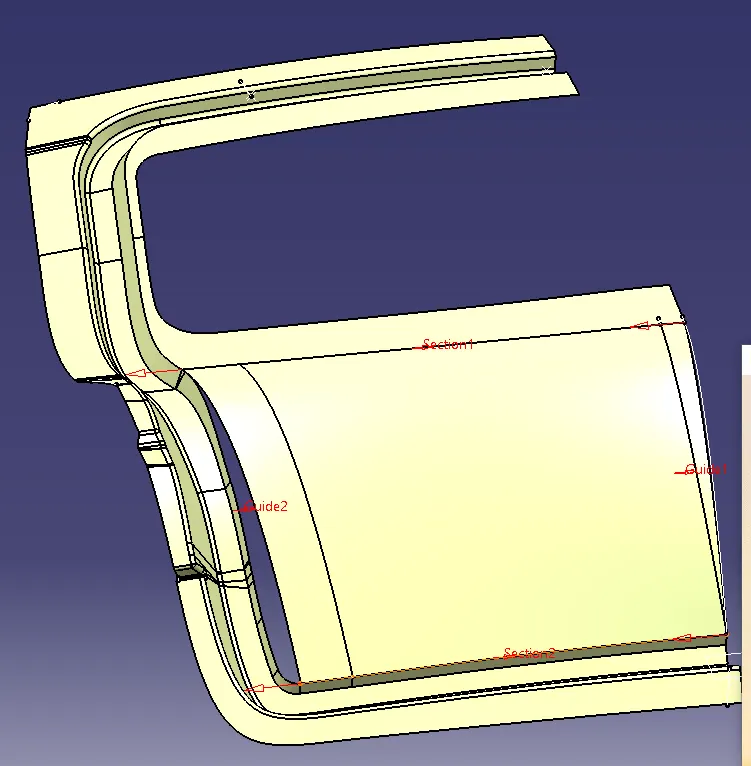
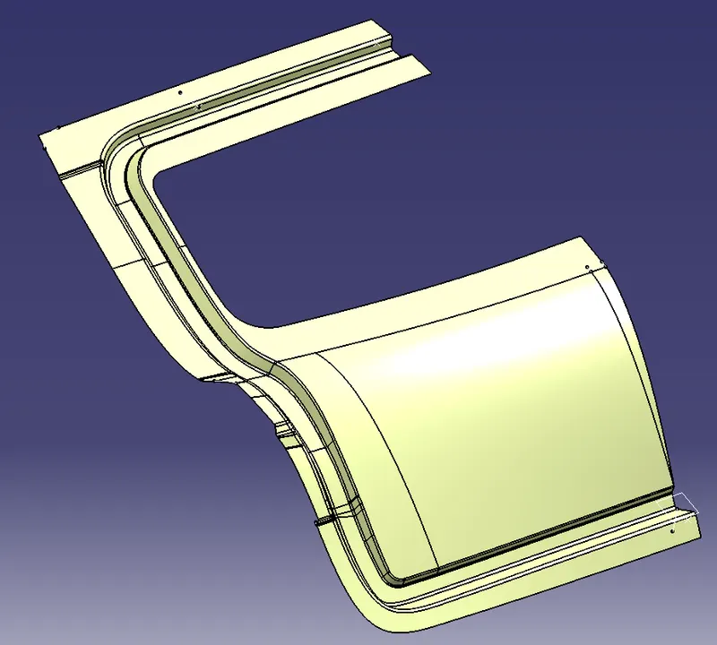
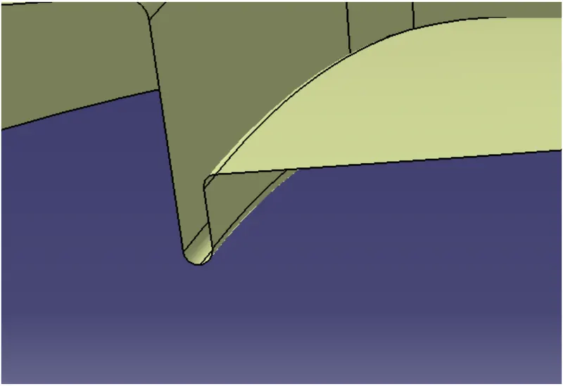
- At the trimming region of the upper and lower panel, the gap is filled using the blend and connect curve
Mastic :
Since we are reducing the overall weight of the door, this mastic providing the strength also serves the purpose of joining the inner and outer panels using the mastic sealants.
The mastic sealants help in reducing the NVH(noise, vibration, and harshness )levels of the door.
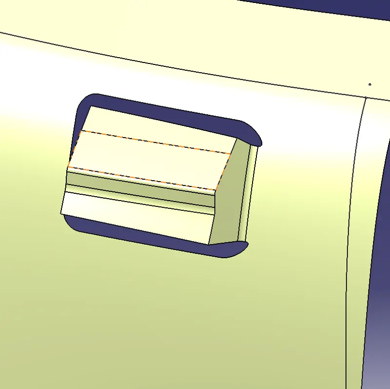
- Create a Sketch of rectangular shape and provide a cut out on the surface. Now, use the sweep option to create the surface perpendicular to the base surface.
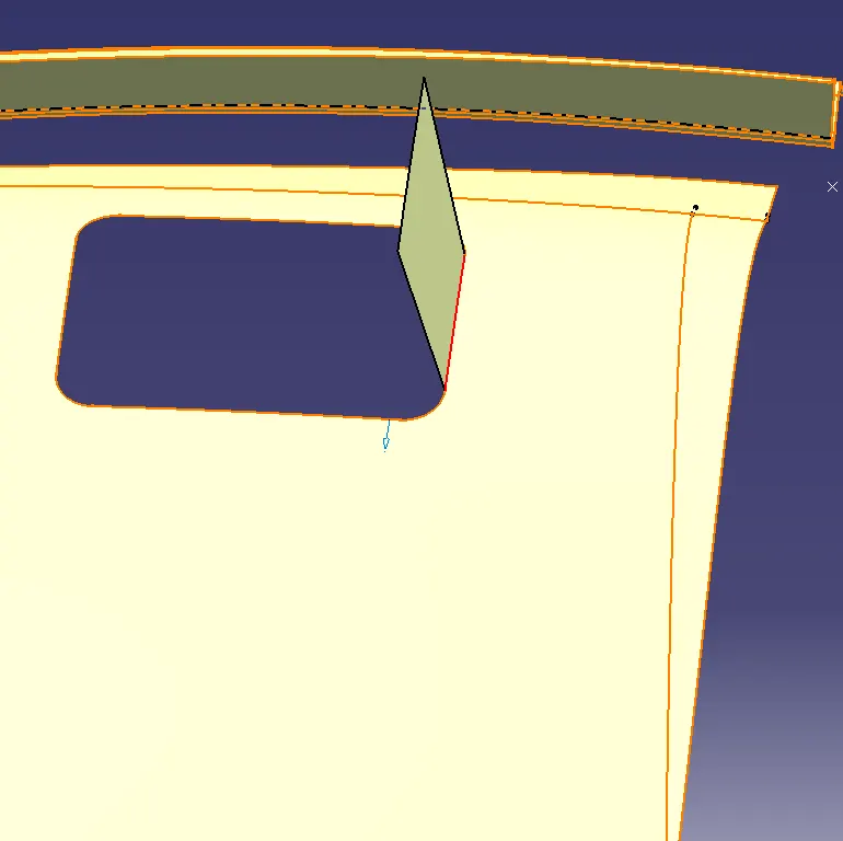
- Offset the main surface to 5mm and trim the surface with the sweep. Cut the unnecessary elements and make sure the trimmed outer surface is less than half of the length of the cut out created at the bottom.
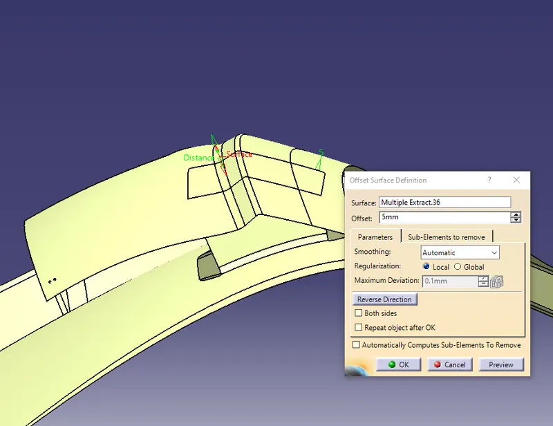
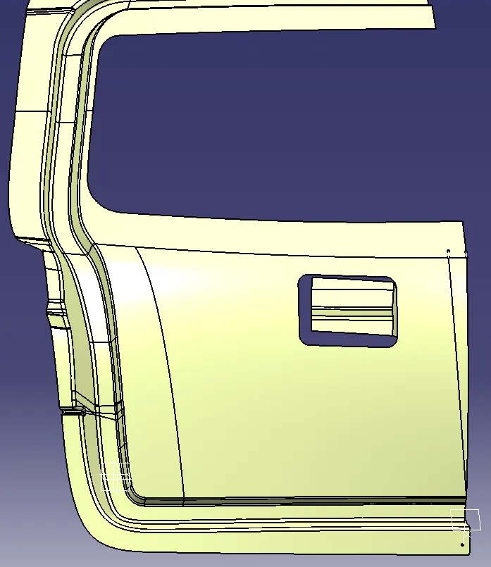
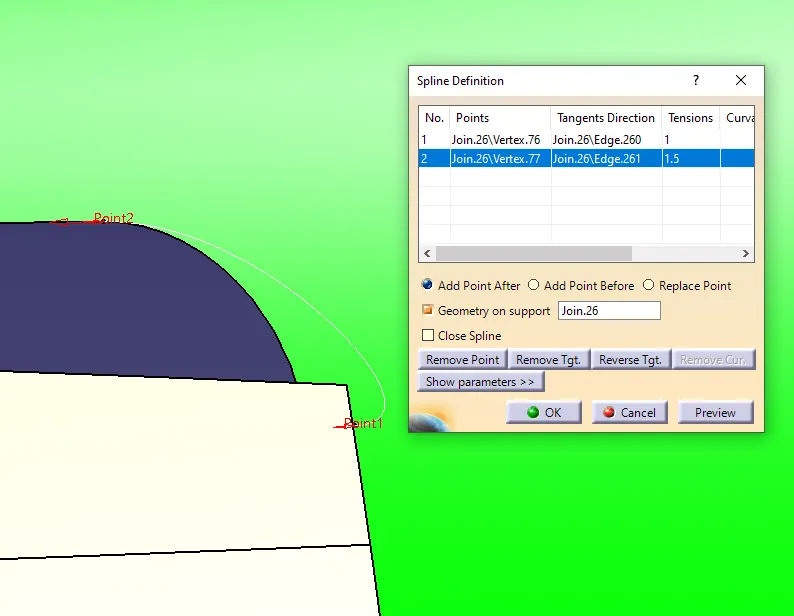
- Now, the free corner of the mastic is provided with relief by drawing the spline and then splitting it with the surface. The edges are provided with the appropriate fillets.
Cutouts and embossments :
Providing the cutouts to the sheet metal backdoor component has two reasons
- To reduce the overall weight
- To provide the path for energy to travel in case of a crash.
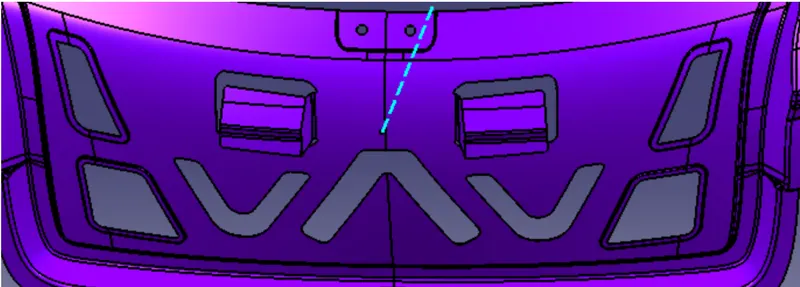
The simulation of the bend, torsion, abuse and endurance test on the back door shows that the force normally travels in the V or Y direction. So the cutouts and embossment are designed in the way that the force is dissipated outward in the V or Y pattern.
- Here, draw a sketch of the required shape such that when the crash happens the load must be distributed to the above providing safety to the people inside the car.
Embossment for hinge, gas stays and latch, and wiper.
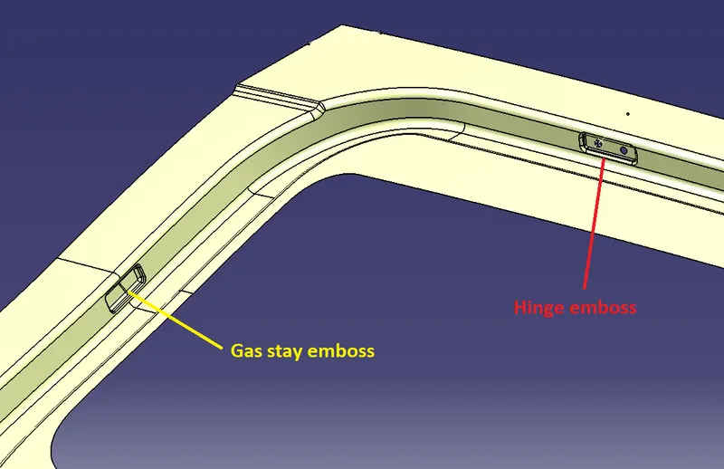
Hinge and gas stay:
Hinge is used to connect the door to the BIW also enables the opening and closing of the hood.
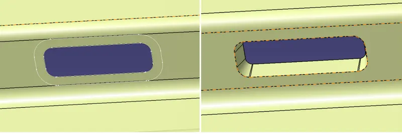
So the embosses are created of the hinge along with reinforcements to provide additional support to the inner panel.
- The Hinges are created at the top of the inner panel using the parallel curves and corner option.
- Use the split option to cut the elements and perform a sweep with an angle of 10 degrees. Offset the surface to 4mm and trim it with the sweep surface. Give the fillets of 4mm to it.
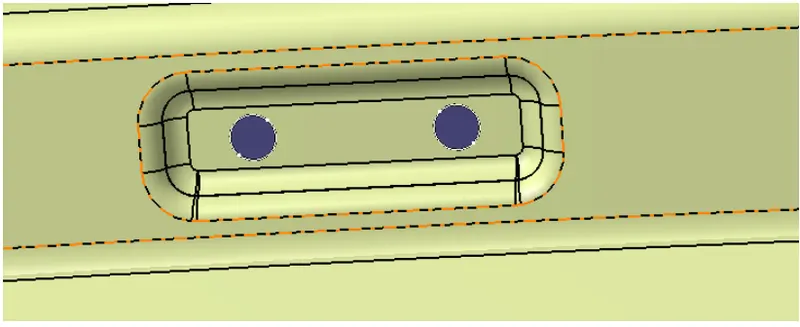
- Similarly, the gas stays embossment is created at the side of the inner panel following the above steps as mentioned for the hinge.
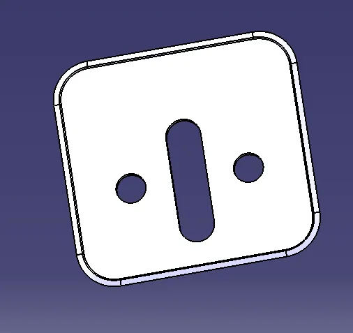
Latch :
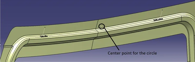
For the latch, it is important to keep the latch embossment according to the trajectory the door opening and closing follows.
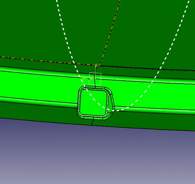
- Take create a center point between the two hinge parts and draw a circle marking the sweep of the lower end of the inner panel. Draw a Tangent to the Circle and create the cut on the tangent area and give the cutouts to it.
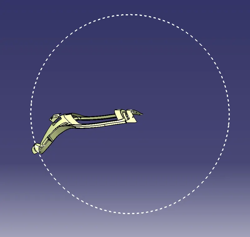
- Now draw the sketch on the plane where the circle intersects the inner panel lower side or where the latch follows the trajectory properly.
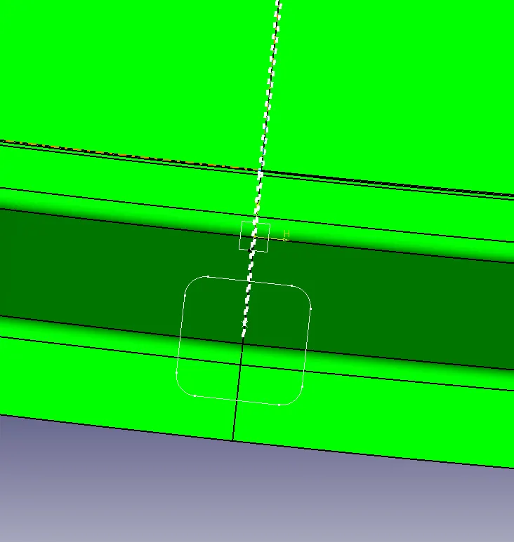
- Sweep the drawn sketch at an angle along the tooling direction.
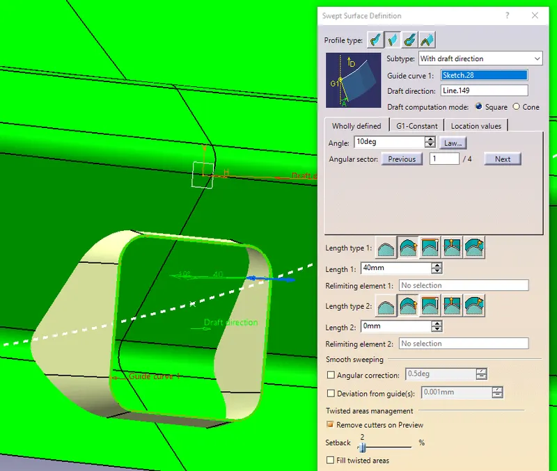
- Now, split the surface with the inner plane and then fill the opened surface followed by stitching all the surface.
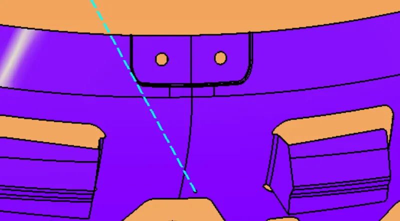
Wiper :
Similarly, the embossment for the wiper motor has been created as shown below.
Reinforcements:
Reinforcements are provided to give strength to parts or regions used for fitting and assemblies. To create the reinforcements steps are as follows:
- Thickened the inner panel and extract the hinge and around surfaces.
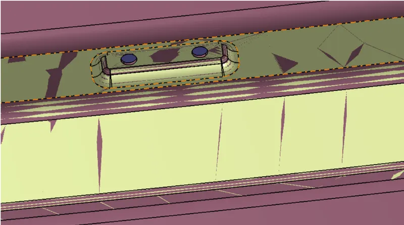
- Now, split the surface to obtain the required reinforcement surface.
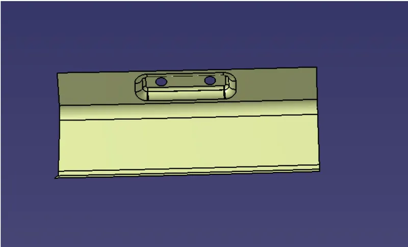
- Thickened the surface to 1-1.2mm since the reinforcement has to be stringer than the panel.
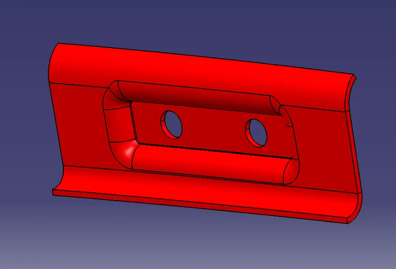
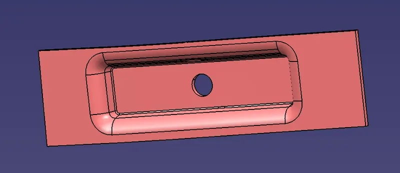
- Similarly, the gas stays, and the latch reinforcement can be formed.
Gas stay:
Latch reinforcement:
Results :
The final backdoor is as shown below :
Inner panel :
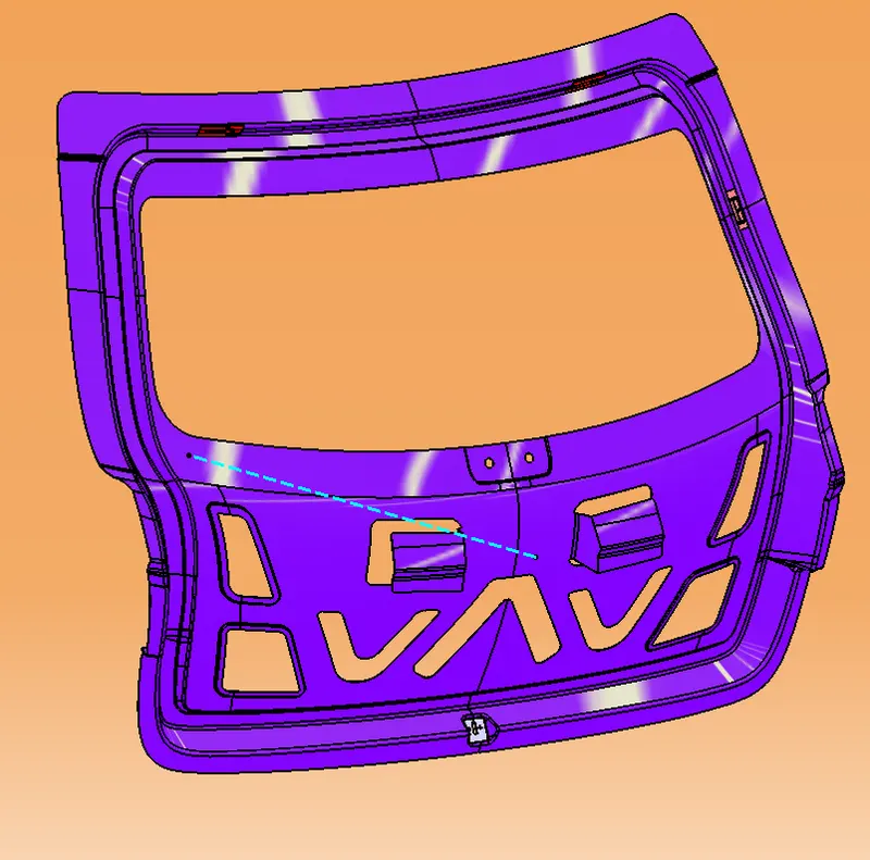
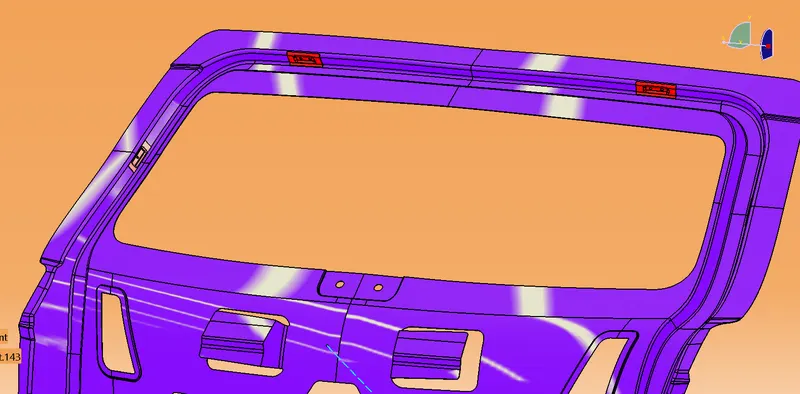
Outer panel :
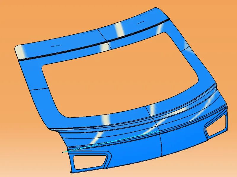
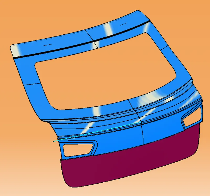
Final assembly :
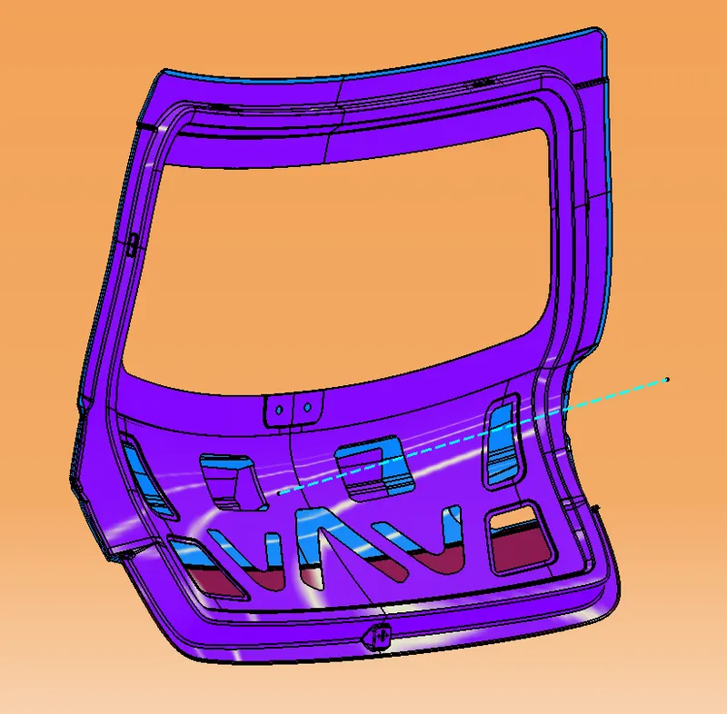
Draft analysis :
Conclusion :
The backdoor sheet metal part body for the Hatchback car was successfully created taking into consideration all the attachments embossments, hemming, and finally with the proper draft angle so that the final component is manufacturable. The approach to design the inner panel was taken in such a way that it dissipates the force outwards in the various crash test.