IP substrate trim panel preprocessing using ANSA
AIM: -
To perform the 2-D meshing on Dashboard using ANSA.
OBJECTIVE: -
Perform the geometrical clean-up on the IP substrate model followed by shell meshing using the stated quality criteria. After meshing the component, the thickness has to be assigned.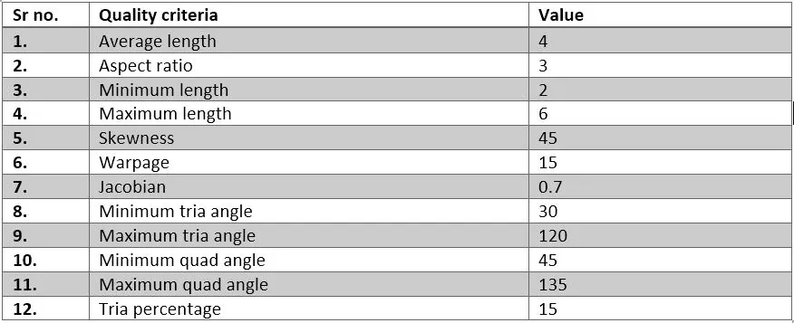
INTRODUCTION: -
A dashboard (also called dash, instrument panel (IP), or fascia) is a control panel usually located directly ahead of a vehicle's driver, displaying instrumentation and controls for the vehicle's operation.
Where the dashboard originally included an array of simple controls (e.g., the steering wheel) and instrumentation to show speed, fuel level, and oil pressure, the modern dashboard may accommodate a broad array of gauges, and controls as well as information, climate control, and entertainment systems.
Your instrument panel contains the following:
The speedometer tells you the speed of your vehicle in MPH and KPH.
The tachometer shows how many rotations your engine is making per minute.
Odometer shows how many miles your car has traveled in its lifetime.
Fuel Gauge shows how much fuel remains in your car's tank.
Gear Display shows which gear your car is currently in.
Turn Signal Indicators flash when your turn signals are on; both will flash if you turn on your hazard lights.
Active System Lights alert you to parts of the vehicle that are activated, such as an open trunk or door.
Other features may include a gauge for alternator voltage, indicators for low fuel, low oil pressure, low tire pressure, and faults in the airbag (SRS) systems, glove compartment, ashtray and a cigarette lighter or power outlet – as well as heating and ventilation systems, lighting controls, safety systems, entertainment equipment, and information systems, e.g., navigation systems.
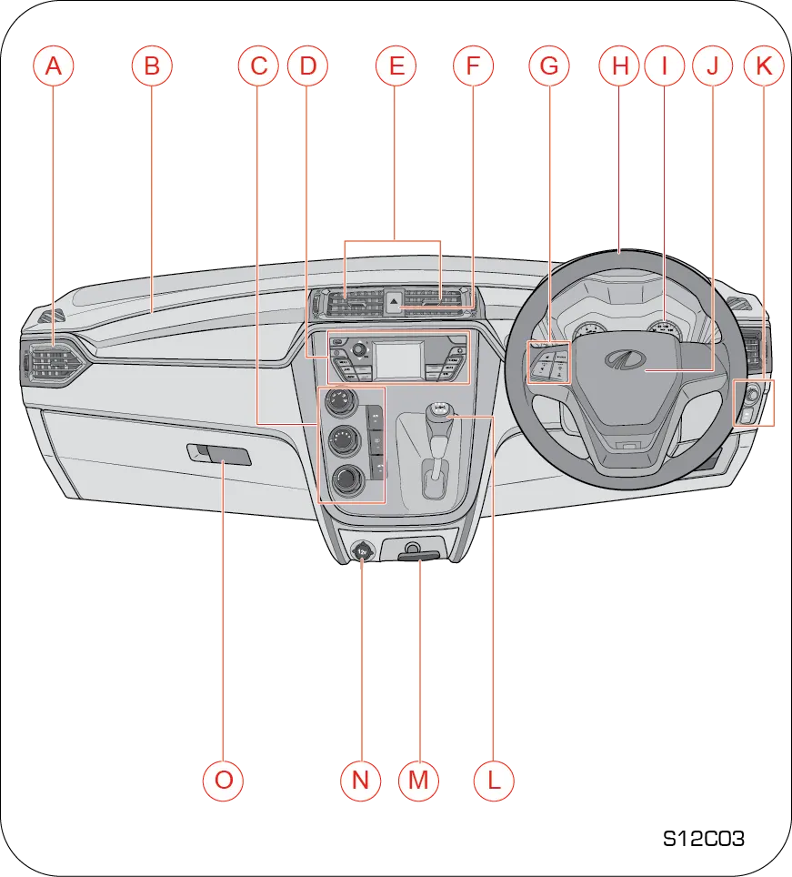
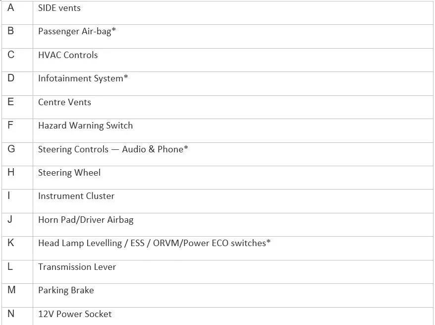
Pic: - instrumental panel of Mahindra KUV 100
METHODOLOGY: -
- Import the model into ANSA GUI
- Checking for the geometrical errors
- Extracting the mid surface
- Topology clean up and assigning the quality criteria
- Assigning the separate PID to every feature
- Perform meshing using quad and tria element
PROCEDURE: -
Step 1-Import the model into ANSA GUI: -
The CAD-based model of the IP substrate is imported into the ANSA interface
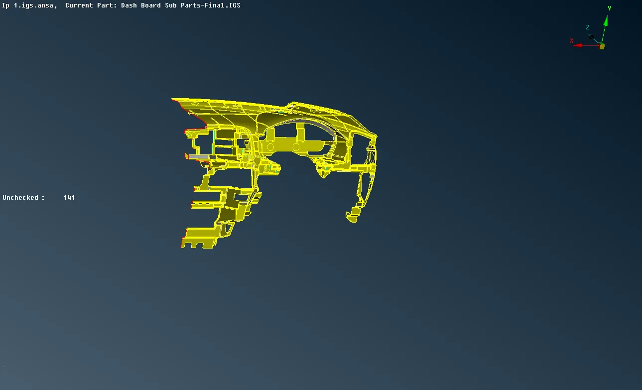
Fig 1- instrumental panel for preprocessing is imported into ANSA
Here we will change the resolution to make the model and its feature finer in order to see their original shapes.
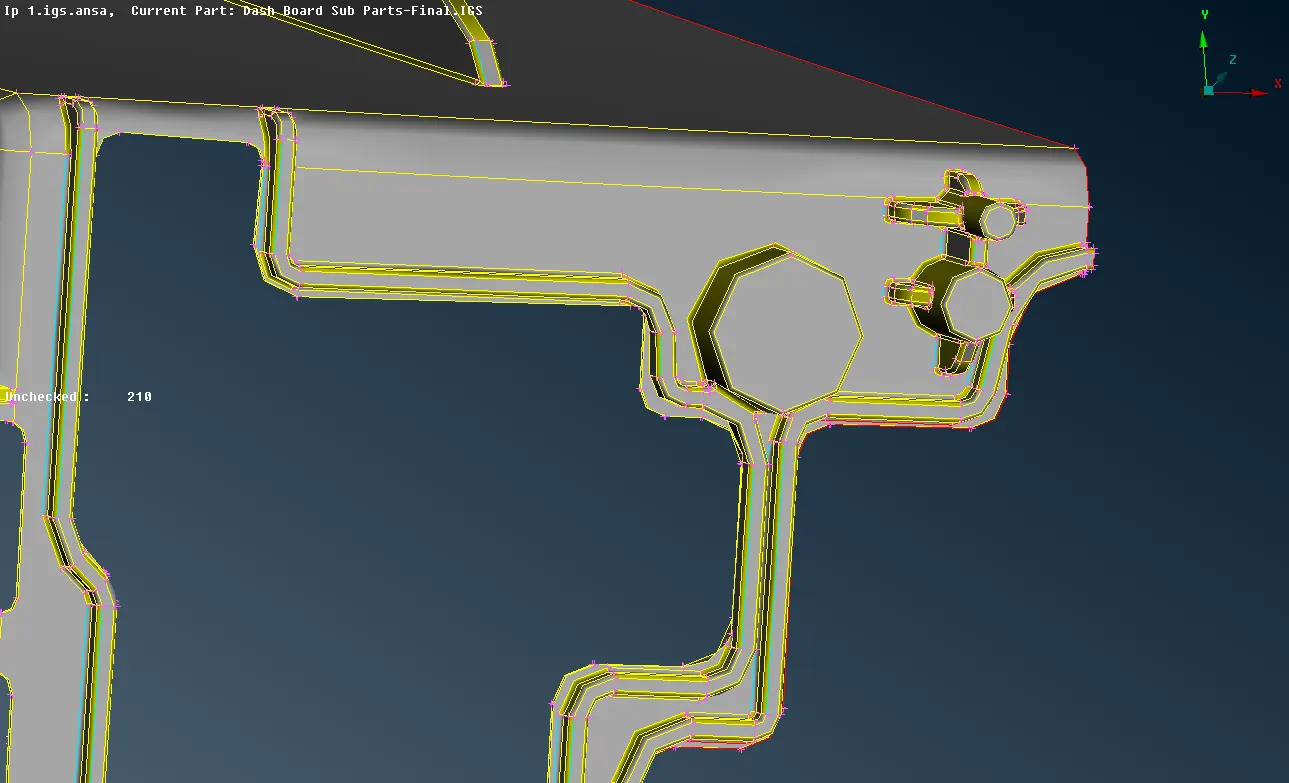
Fig 2- Feature are not good visually due to low resolution
To change the resolution of the model we can use the LENGTH option
Mesh > LENGTH> 4
Since 4 is also the average length for the model.
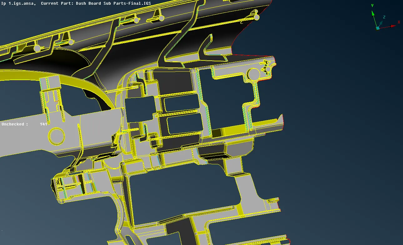
Fig3- Resolution of the model is changed
Step 2 -Checking for the geometrical errors: -
Generally, CAD data is provided in *.igs format. Geometry cleanup cleanup
at least have the basic knowledge of CAD. Before starting the job,
- Free edges
- Scar lines
- Duplicate surfaces
- Small fillets
- Small holes
- Beads
- Intersection section of parts (assembly (assembly of components)
To check for the errors
Checks manager >check> geometry
Turn on the triple cons and single cons as there should not be any overlapped and geometry must be closed.
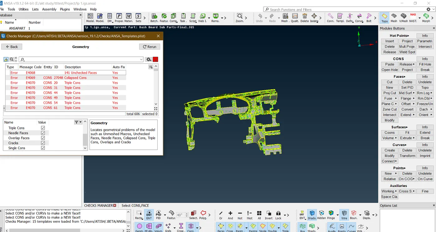
Fig4 – Geometry errors encountered in the dashboard panel
As there are around 140 unchecked faces, solving those individually will consume much time. As to save time we will automatically fix the tool to resolve the errors. Rest that are not resolved will be solved manually.
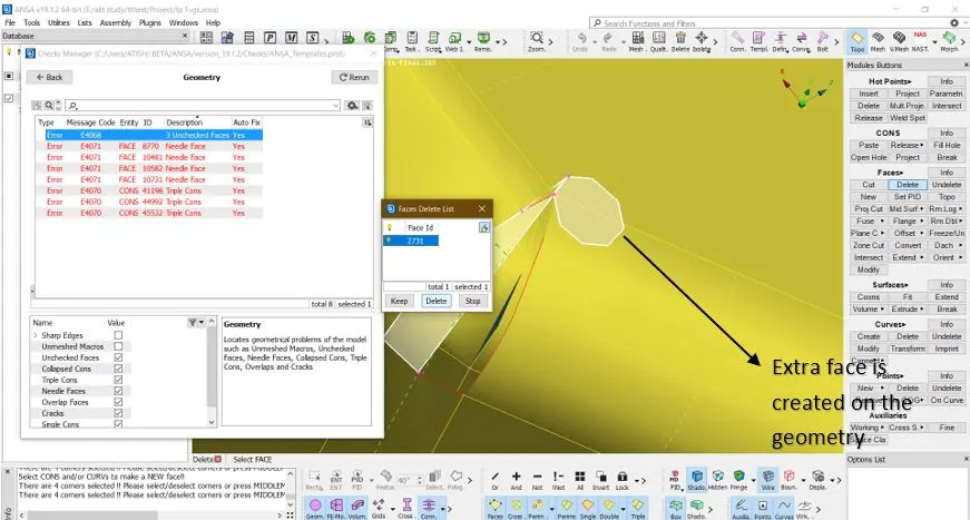
Fig5 – Unchecked faces eliminated by deleting and creating the new surface
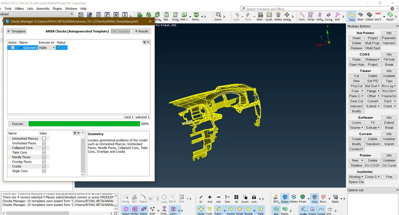
Fig6 – The geometry is cleaned.
Step 3- Extracting the mid surface: -
Measuring the geometry: -
Before extracting the mid surface, the model has to be analyzed and certain measurement is carried out as to decide how to proceed with extracting the mid surface.
UTILITIES > MEASUREMENT
Also, the measured value of each region can be used to assign the thickness to the mid surface.
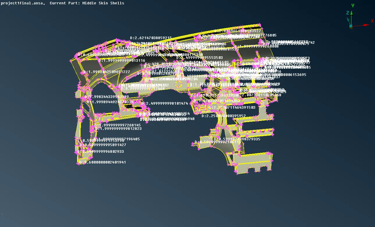
Fig 7- Measuring the geometry
After the analyzing the model mid surface can be extracted by a various method such as
- Offset
- Middle
- The automatic way by using SKIN or CASTING
Offset: -
When the geometry is having a uniform thickness offset method can be used to extract the mid surface. Here the model has a thickness of 0.6mm so the offset value has to be 0.3mm. Notice the direction of the arrow indicates the mid that will be created from the parent surface. The arrow here points downward, so no negative sign is used.
Faces > offset > faces
Also using the FEATURE ANGLE option, the outer body of the panel is only selected and all the ribs are eliminated for offset.
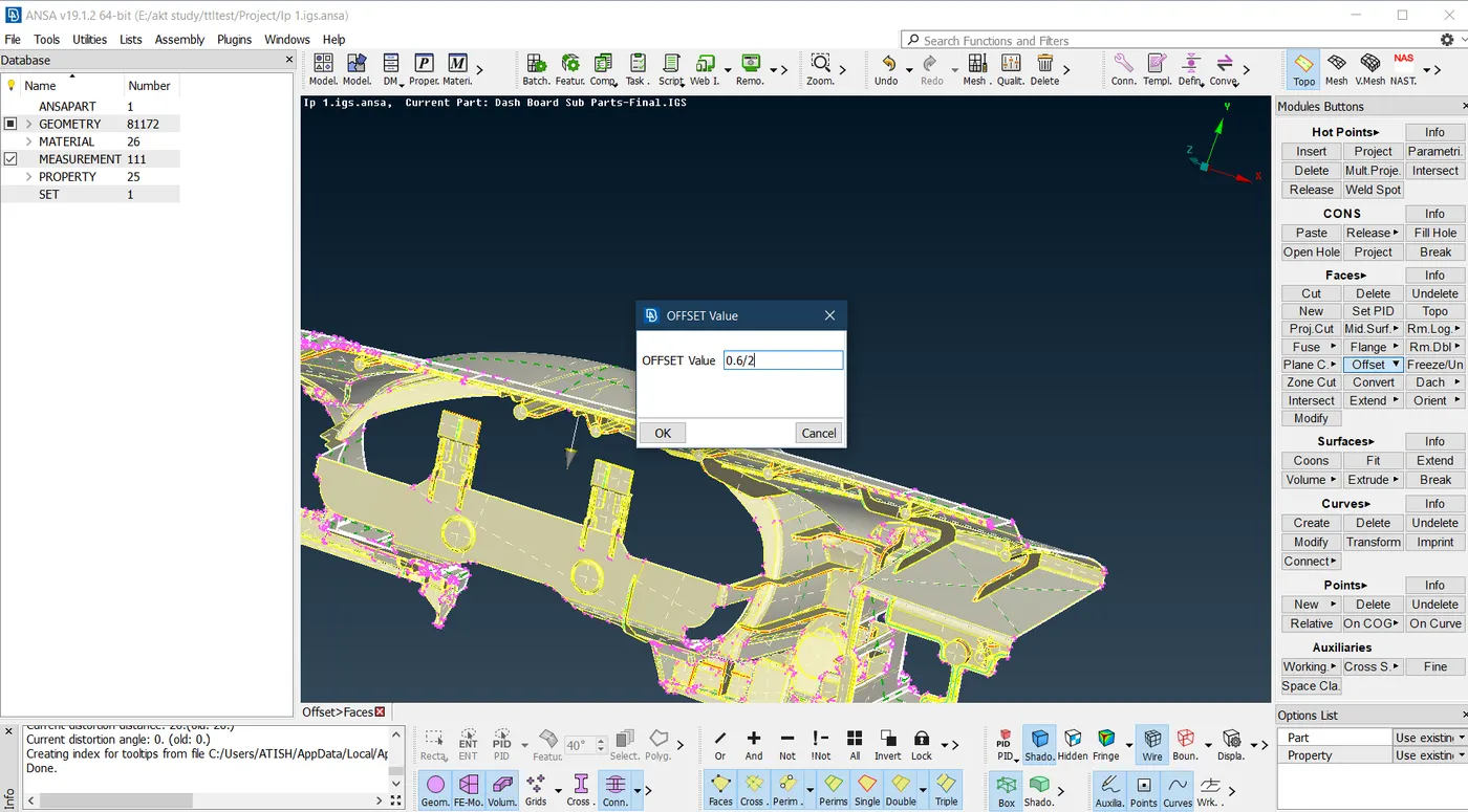
Fig 8- offsetting the outer surface of the panel
Middle: -
Generally, the ribs don’t have uniform geometry and thickness so it’s not possible to use the offset method. The MIDDLE option is preferred to extract the mid of the ribs.
Faces >MIDDLE>SINGE
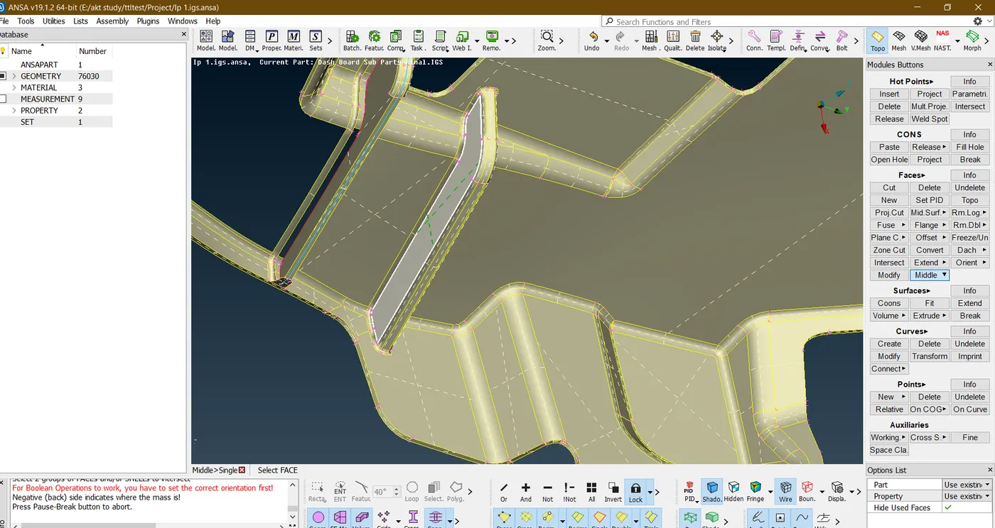
Fig 9- using MIDDLE to extract the rib mid surface
Extend: -
The one drawback here is that the rib true height is not captured because its filleted area is not used for the middle. In order to capture the true height of the ribs, the EXTEND TOOL is used.
Faces > EXTEND
EXTEND tool is also used for joining the ribs to the base of the surface.
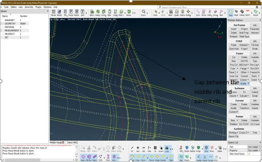
Fig 10- The rib true height is not captured by the middle tool
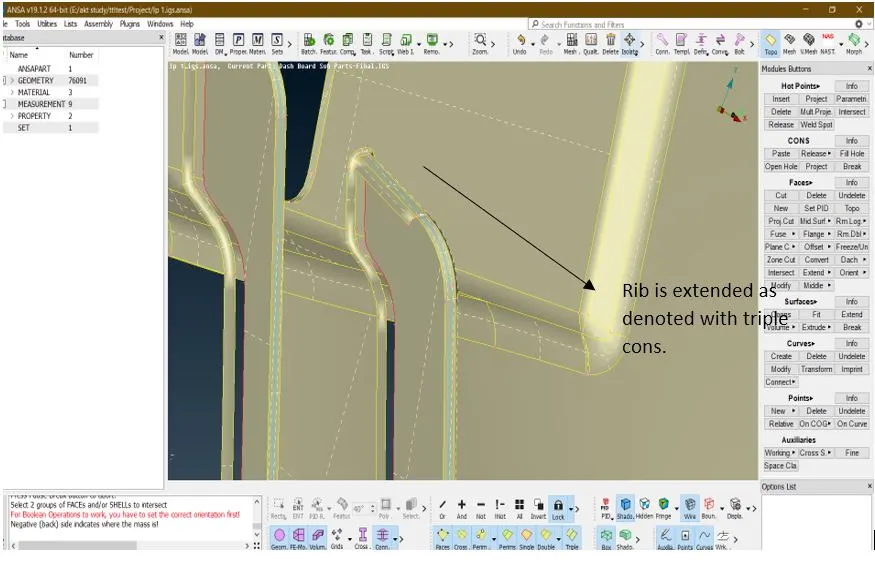
Fig11- Rib true height is attained using extend the tool.
Intersect: -
When the two intersected, there have to con (triple cons) between them. If it does not happen the INTERSECT tool is used to make the intersection between the two.
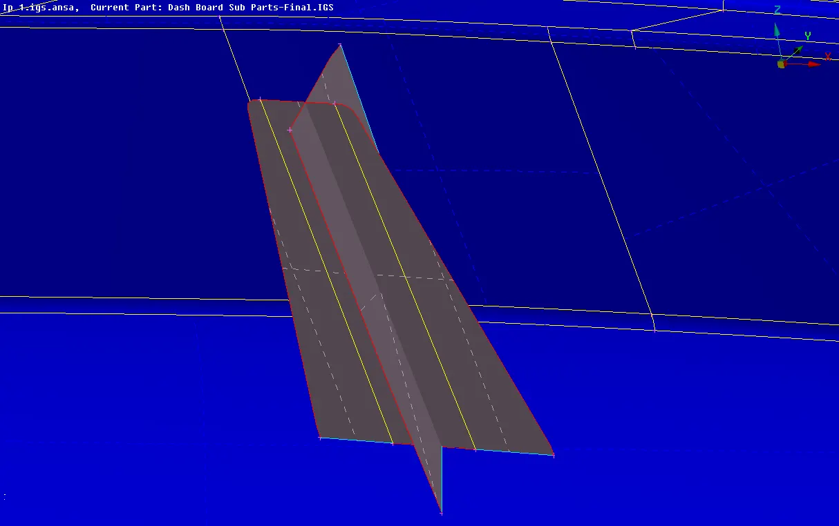
Fig 12- No intersection between two surfaces
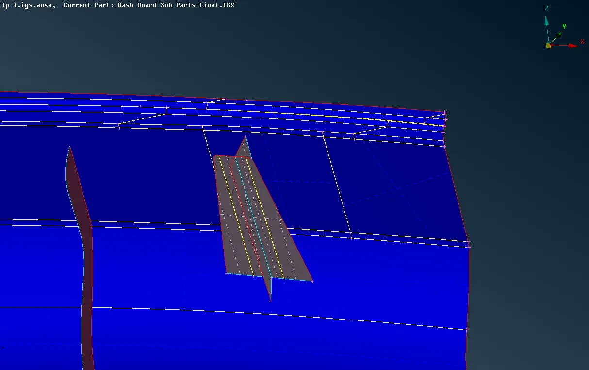
Fig 13 – two surfaces are intersected using INTERSECT tool
Note: -
The dock(cylindrical) that are present with the ribs cannot be mid surfaced because it is hollow from inside. Also, if they are meshed using volume, and connecting the rib to the mid surface requires connection which is not the objective of this project. Here they are not designed with mid but by a cross pattern of the ribs.
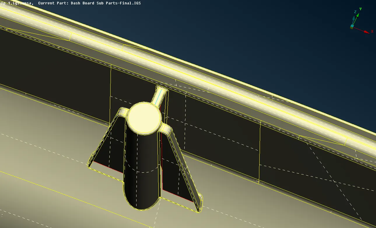
Fig 13- The dock (cylindrical) part cannot be mid surfaced.
Using all of the above tools, the mid surface of the IP substrate panel is extracted.
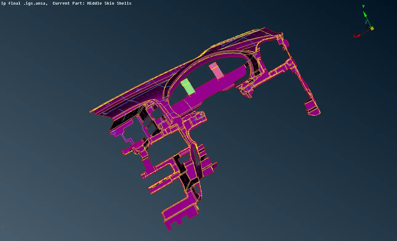
Fig 14- Final mid surface for the dashboard panel
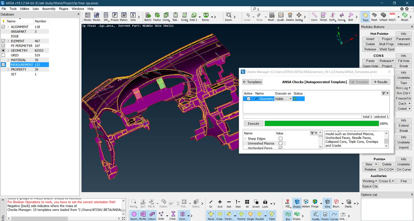
Fig15- Created mid surface has no error.
Step 4-Topology clean up and assigning the quality criteria:
The topology cleans up means removing any extra cuts and hot points over the surface of the component. Topology clean-up includes the measurement at the certain area where the area falls below the minimum criteria of the element length followed by its defeaturing.
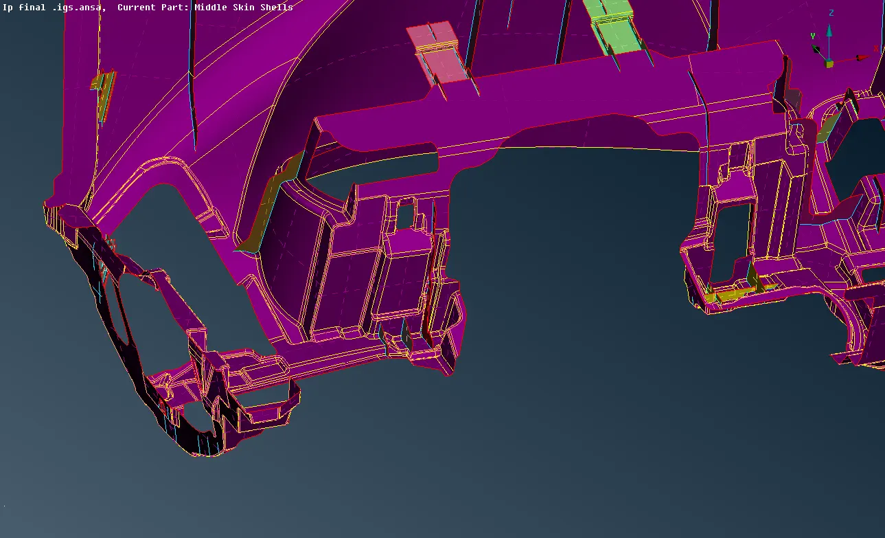
Fig16 - Original model had many lines near to each other.
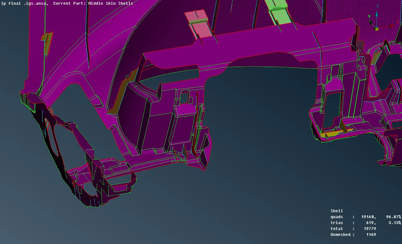
Fig17- Cleaned up model
Assigning the stated quality criteria, parameters, and performing surface mesh: -
The quality criteria are followed before performing the mesh according to the requirement.
- Minimum and maximum length
Minimum as 3
Maximum as 7
This to define the distance between nodes over the surfaces. Any two nodes having a distance less than 3 and greater than 7 will fail in element size
- Average length as 5
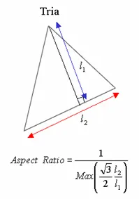
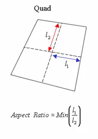
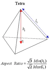
- Aspect Ratio:
The aspect ratio of the 2D element is defined as the ratio of its shortest edge length to its longest edge length. A square has an aspect ratio of 1 since its sides have the same length. As it gets away from the square shape, the aspect ratio becomes smaller than 1.
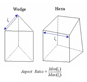
- Skew Angle
An angle is formed by the two lines which pass through the midpoints of the sides of the quadrilateral. The skew angle represents the absolute value of the difference between the angle and 90 degrees. A rectangle has a skew angle of 0 since the formed angle between lines is 90 degrees. For the triangle and quadrilateral elements, the skew angle is found as shown in the figure. For solid elements (Tetra, Hexa, Wedge), it calculates the skew angle for each element's faces and assigns with the minimum value.
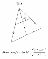
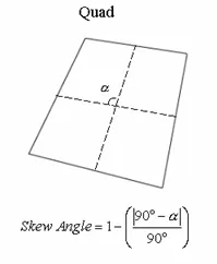
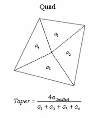
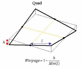
- Warpage
The warpage of the quadrilateral elements is defined as the deviation from a best-fit plane that contains the element. It is not always a case to define a plane with 4 nodes. Therefore, a node of the quadrilateral element may be formed outside of a plane. The warpage is a measurement of how this node has deviated, and as it gets closer to 0, the element becomes more planar. For the quadrilateral elements, the warpage is found as shown in the figure. For solid elements (Hexa, Wedge), it calculates the warpage for each element faces and assigns with the maximum value.
- Jacobian Ratio
The Jacobian calculation is done at the integration points of elements commonly known as Gauss Point. At each integration point, Jacobian Determinant is calculated, and the Jacobian ratio is found by the ratio of the maximum and minimum determinant value. The Jacobian Determinant of 2D elements is calculated after it has been projected onto a plane, and the determinant of 3D elements is found by direct calculation.
If the quadrilateral element is not convex, the negative Jacobian ratio will be obtained, and elements with the negative Jacobian Ratio cannot be solved with the correct result.
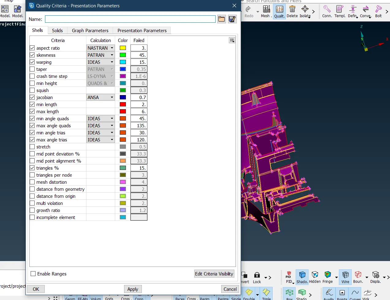
Fig 18- quality criteria
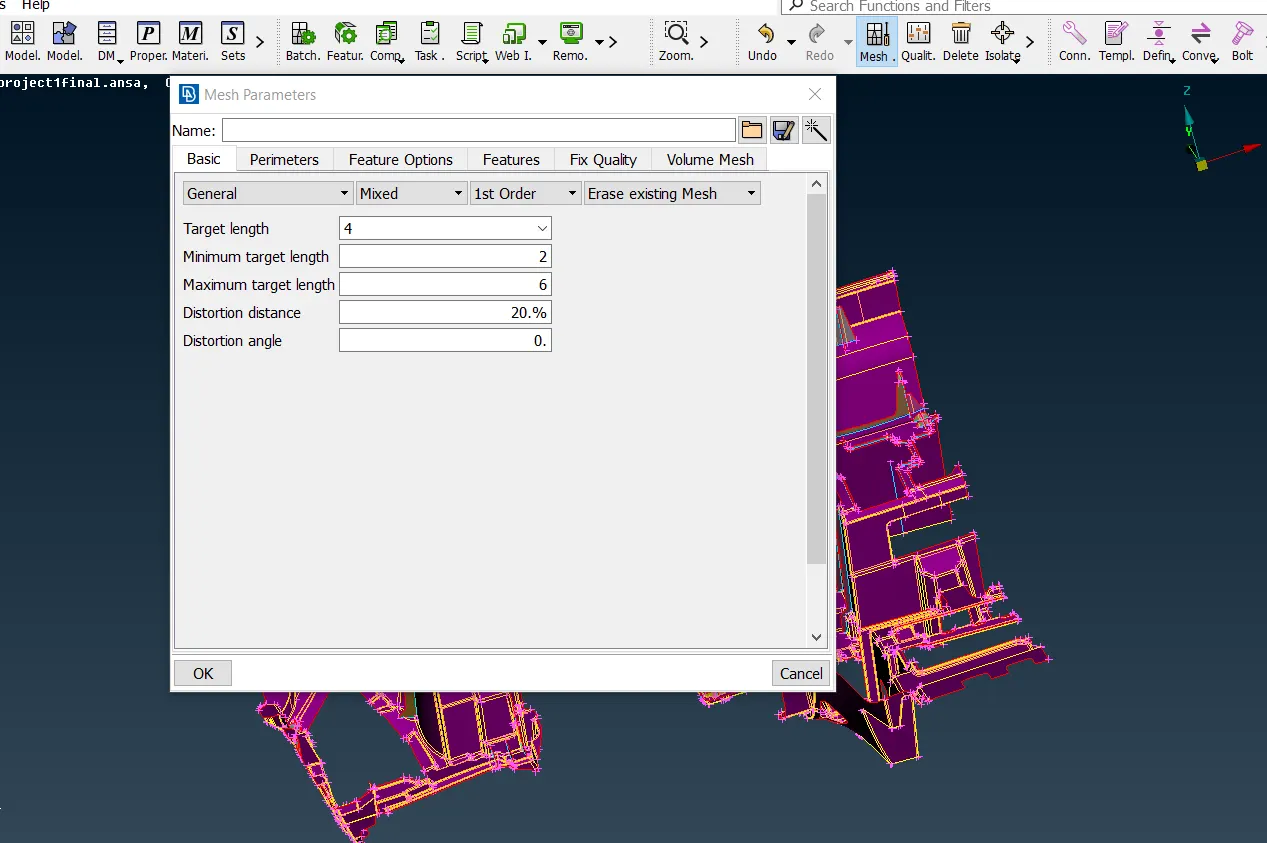
Fig 19- Mesh parameters
Step 5 – Assigning the separate PID to every feature: -
PID means property identity. PID caries thickness, density, mass, position ratio, etc. If the component is having constant thickness throughout, it is alright to have a single property card for the mid surface. But when the component is having varying thicknesses over its surface, it is necessary to assign a separate property card to each and every region.
Here while assigning the property each region will have its own thickness value as we calculated from parent geometry also, we will give each region separate color for better understanding visually.
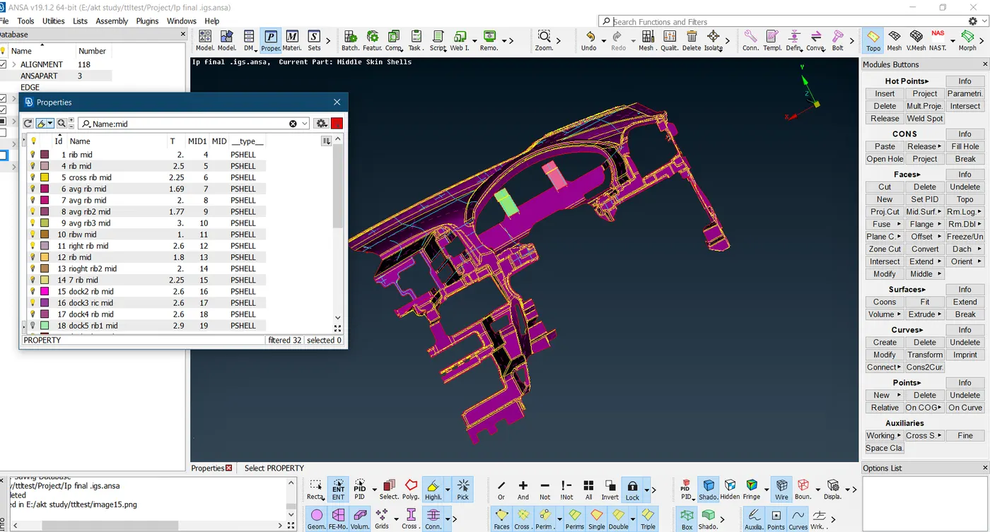
Fig 19- Assigning the thickness to each feature
Step 6- Perform meshing using quad and tria element: -
Perform the meshing keeping in mind that no rotating quads and no opposite tria element present near each other also with proper mesh flow:-
Before performing the mesh flow make sure to define the length of the perimeter and macros as 4. This is to ensure that adjacent nodes have a distance of 4 between them.
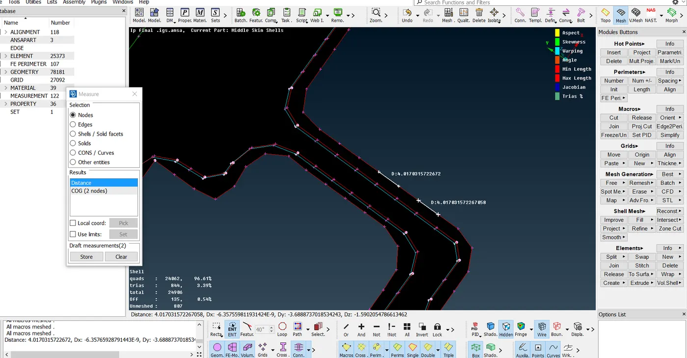
Fig 20 – average length as 4 (distance between two nodes)
Switch to HIDDEN MODE then starting with the mesh generation. here we are using two mostly method of mesh generation as
- Best
- Spot mesh
Rectifying the errors of mesh :
Warpage errors: these errors are shown in sky blue color here occurs in quad elements . to rectify this kind of error use the split option and try to split the quad into tria
Min and max length error: these error arrises when an element does set into defined value .to rectify these use split option or add the number of cons.
Rotating quads: to rectify the rotating quads use the split option, split the quad into tria.
Opposite tria: these can be eliminated by using the split option and also using the paste option to join them as one
Mostly use the tool here to remove the errors are :
- Reconstruct
- Smooth
- Split
- Paste
For example:-
EDGE2PERIMETER:-
In certain regions like here, we see that along the edge, there is an element that is failing in skewness. These kinds of errors can be removed by using the EDGE2PERIMETER option.
MACROS>EDGE2PERIMETER
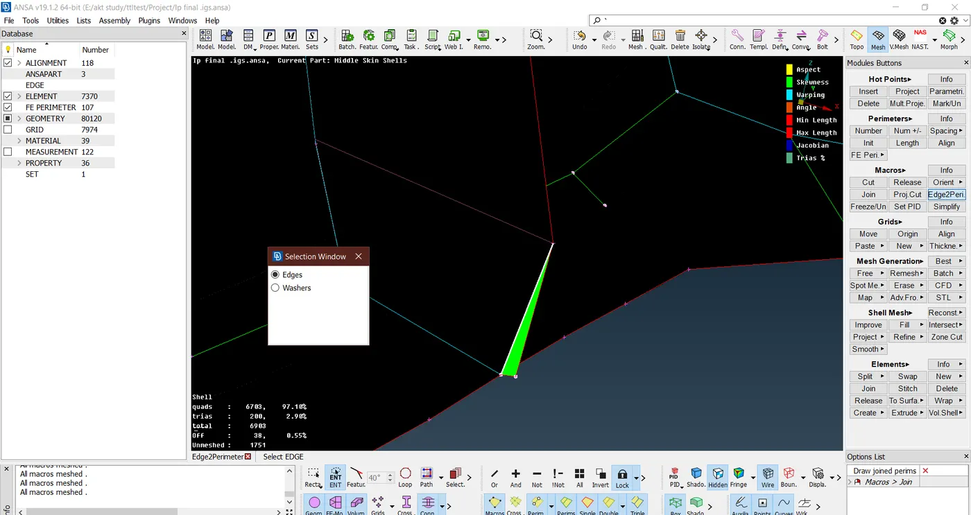
Fig 21 – using edge2perimter tools resolve skewness
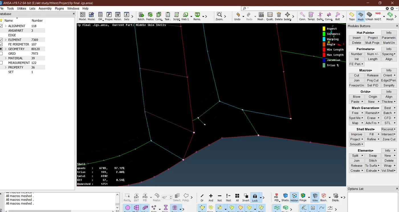
Fig 22- Small area failing for skewness near the free edge can be eliminated.
Paste tools: -
The paste is used to remove the opposite tria near to each other.
Grids > Paste > Paste Node Pairs > COG
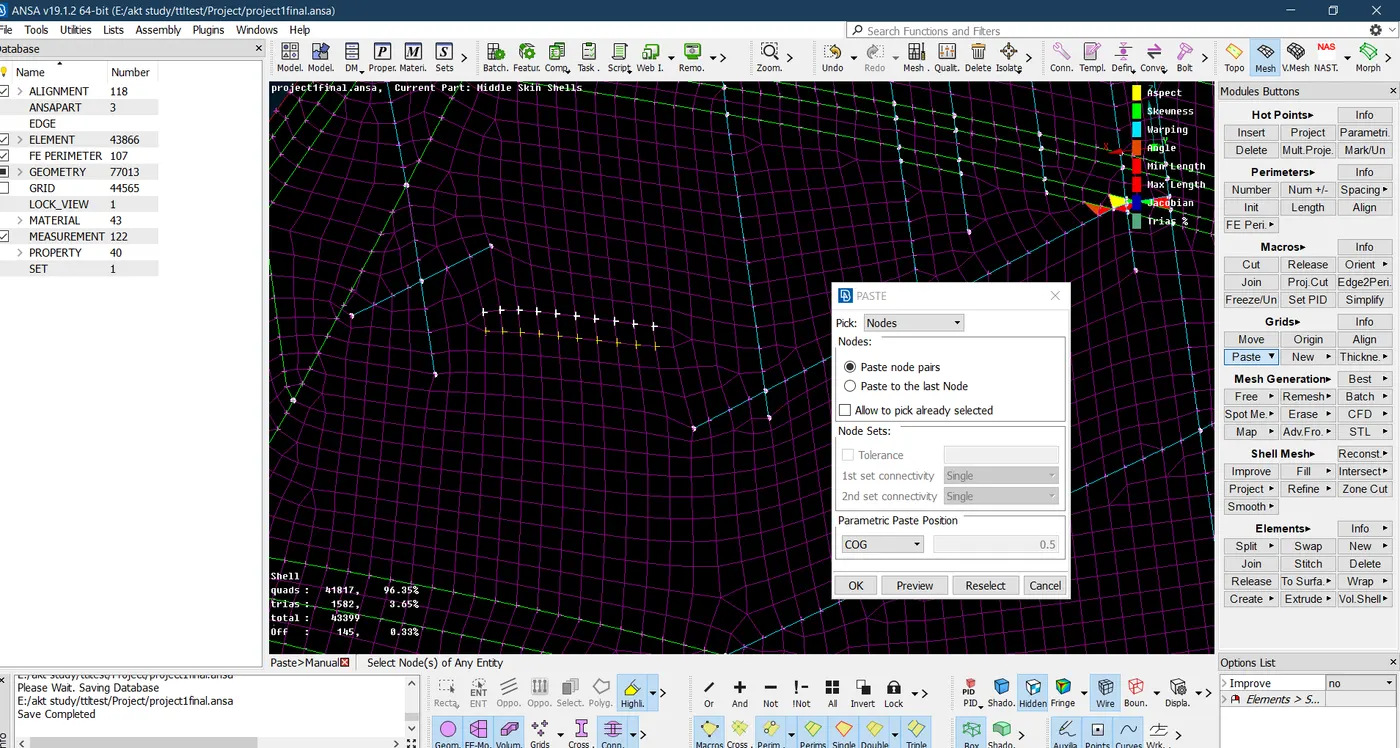
Fig 23- Paste tool used to remove opposite tria
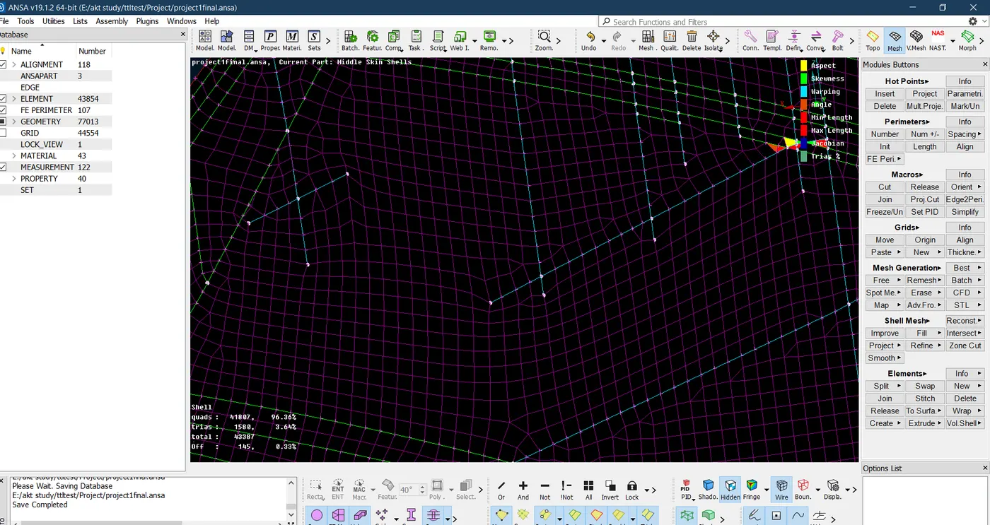
Fig 24- Opposite tria is eliminated using paste tool
But here in a certain region, there are errors that cannot be removed. Like in the below figure we can see that region is failing in minimum, jacobian, angle errors.
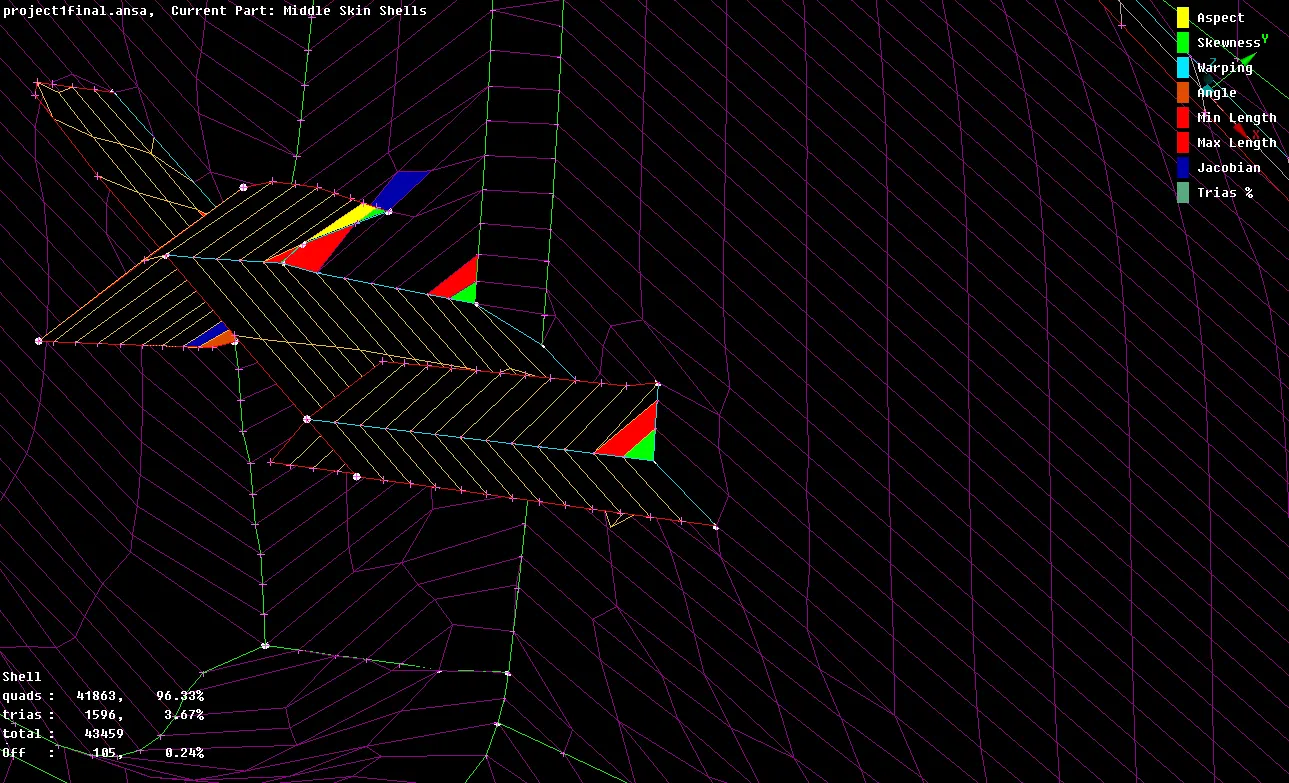
Fig 25- errors at the connection between two faces
If switch to wireframe mode we can see that there are triple cons in that region. So, we cannot remove that triple cons even if we try so. Here we cannot solve that error.
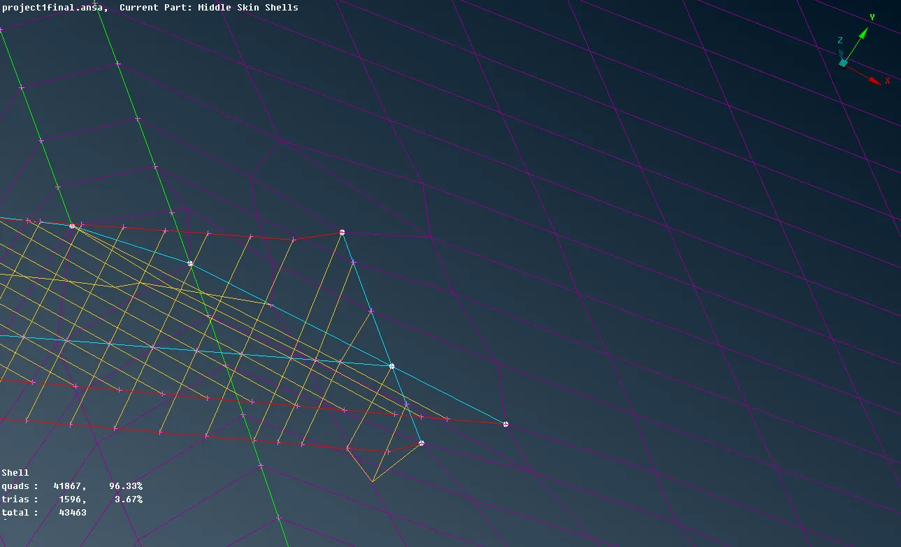
Fig 26- wireframe mode show triple cons (errors cannot be resolved).
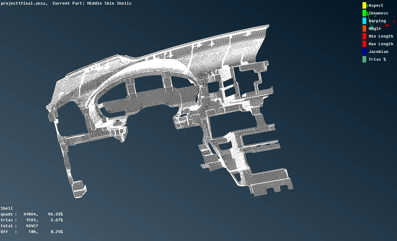
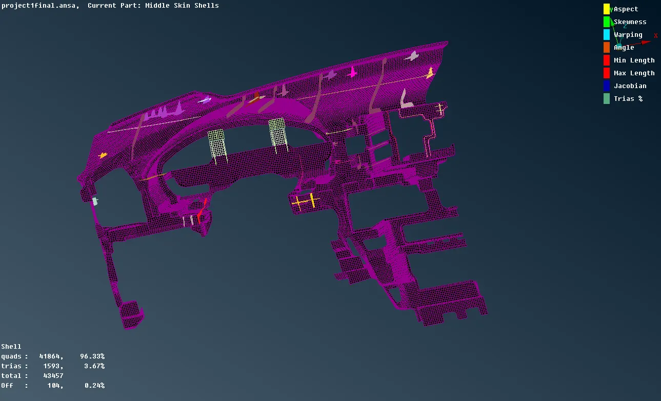
Fig 27 – Final mesh of the dashboard panel
Apply thickness to the final mesh:-
As we gave thickness to the mid surface in the PID manager, we can now see the thickness of the mesh using DRAW SHELL AS SOLID in quality criteria.
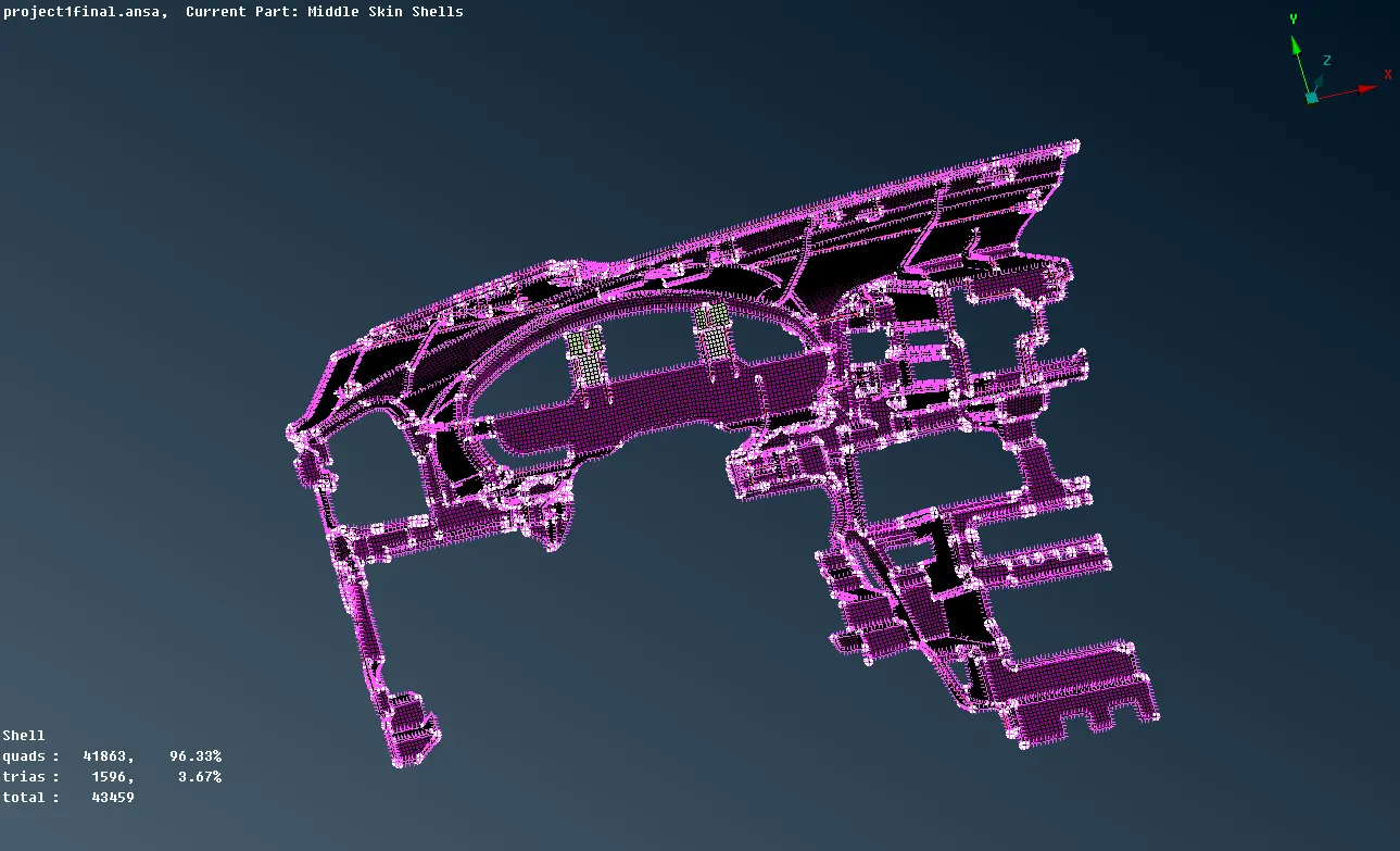
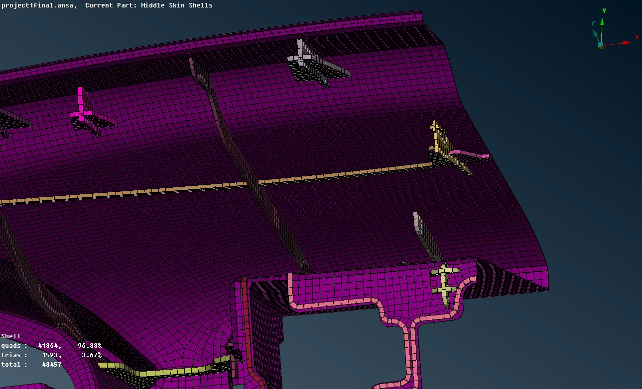
Fig 28- Model after applying thickness
To see if that the surface is extracted properly, we can check by comparing these mesh surfaces with the parent surface. If the glitching happens between two then the mid surface is extracted properly.
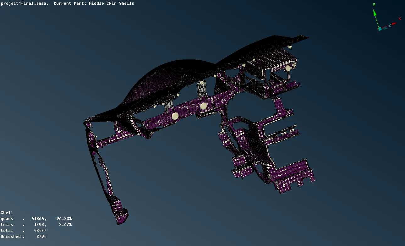
Fig 29- Comparing the mid surface to the parent geometry.
RESULTS: -
|
No. of quad elements |
No. of tria element |
No. of errors |
Total no. of elements |
|
41684(96.33%) |
1593(3.67%) |
104(0.24%) |
43457 |
LEARNING OUTCOMES:
- Learned to extract the mid surface by using the different tools as offset, casting, and middle.
- Learned to perform the topology cleanup before performing mesh.
- Learned to perform the shell mesh.
- Learned to solve the failed elements using the paste, split, and edge2perimeter tools along with the reconstruction and smooth tools.
- Learned to assigned the average thickness to the faces having varying thicknesses.
CONCLUSION:
The mid surface followed by the shell mesh for the dashboard/IP Substrate panel is carried out successfully. Some areas were neglected especially hollow cylindrical as they have to design using volume mesh which was not objective here. There are some errors in the model that cannot be resolved due to the intersection of two faces forming triple cons also at the region of the ribs that considerably near to the free edge causing minimum length errors.
Link for the model: https://drive.google.com/drive/folders/1GczaUfGynfMoUp-70o67uYiEYPlohQ54?usp=sharing