Design of backdoor
AIM:
To Design the outer upper and lower panel, inner panel with the necessary reinforcements by following the Master section with the design parameter for the given class A surface with software CATIA V5.
INTRODUCTION:
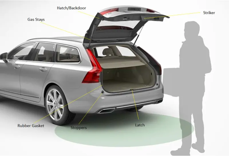
A door is a hinged part which is used for entry and exit of the vehicles. Back doors are one of the type doors of the vehicle which are located next to the passenger seat which provides access to the luggage compartment. In most of the cars, these back doors are operated with the help of gas stay which in turn reduces the effort required to lift open the door. Some luxury cars have powered backdoor which in turn is driven by an electric motor. This kind of system is also called a powered trunk lid system. Hatchback or station wagons are sold as 3 door or 5 door models. In this case, the rear hatch is classified as door this is because it enters the passenger compartment. The naming is mainly used in Europe countries. In case of safety, the back door designed should meet the safety requirement for the rear collision.
Types of the back door
Top-Mounted :
This type of back doors is used in a station wagon, pickup truck and some of the sport utility vehicles. Today’s modern cars use top-mounted tailgating systems which are both powered and also gas stay supported. These top mounted tailgates provide greater rear visibility compared to side-mounted or bar doors which have canter pillars in it.

Side Mounted Doors :
As the name signifies side-mounted doors are the one which is used in the van type MPVs, SUVs, pickup truck vehicles. These side-mounted doors or barn doors are a lot easier compared to top-mounted doors. These doors are generally smaller in size and can be easily accessed.

Types of mechanisms for Rear Door:
Gas stays:
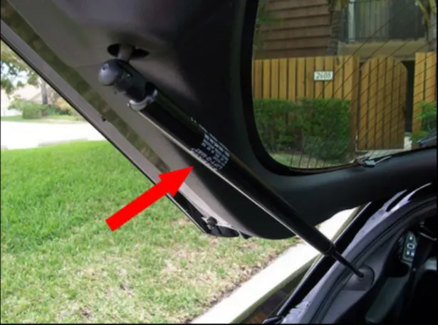
Gas stay types backdoor/liftgate/tailgate is an ideal and most commonly used tailgate mechanism from lower segment car to luxury car segment. The ideal components of tailgate consist of a hinge, door, gas stay and some rubber beadings for sealing of door.
Powered lift system:
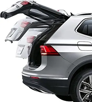
Power trunk lid system is another sophisticated way of trunk/liftgate opening mechanism which is to automatically open and close of the trunk/liftgate and release of the latch by the touch of a button.
Components to create:
- Outer Upper Panel.
- Outer Lower Panel.
- Inner Panel.
- Gas Stay Reinforcement L And R.
- Hinge Reinforcement L and R.
- Striker Reinforcement.
- Wiper Reinforcement.
PROCEDURE:
1. Checking the Geometry:
- Once the model is opened, we get a Class A Surface of the back door.
- there are so many open boundries in that we need to rectify those thing and need to recreate it
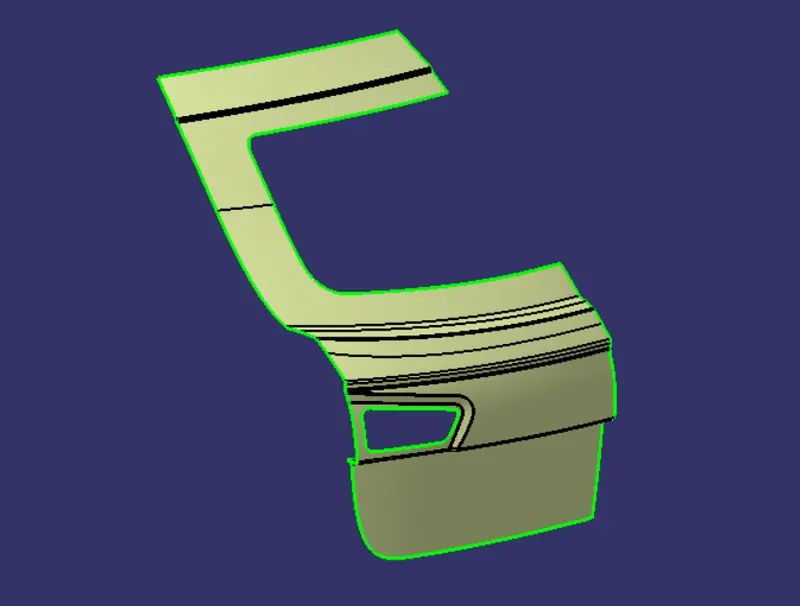
- Try joining the Upper surface of the car, if the surface sews together, we get the outer surface and if the surface didn’t join then we need to create the surface by using studio surface tool
- Create the fillet areas, Tail Lamp areas as those areas will be vulnerable and are unable to join together.
also we need to extract newly modified class a surface
Tooling Direction
Tooling direction is the direction the mould takes to make the part. It is basically the direction that the mould pulls apart. The mould is built in two separate pieces, a cavity side and the core side. The core pulls apart from the cavity and that is the Tooling Direction.
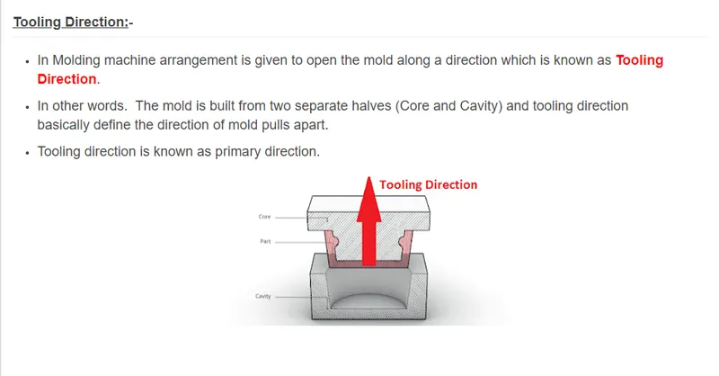
Core is the male part which forms the internal shape of the moulding. Cavity is the female part that forms the external shape of moulding.
Parting line is the line of separation on the plastic part where the two halves of the plastic injection mould meet, i.e. where the core and cavity meet.
-
2. Tooling axis creation:
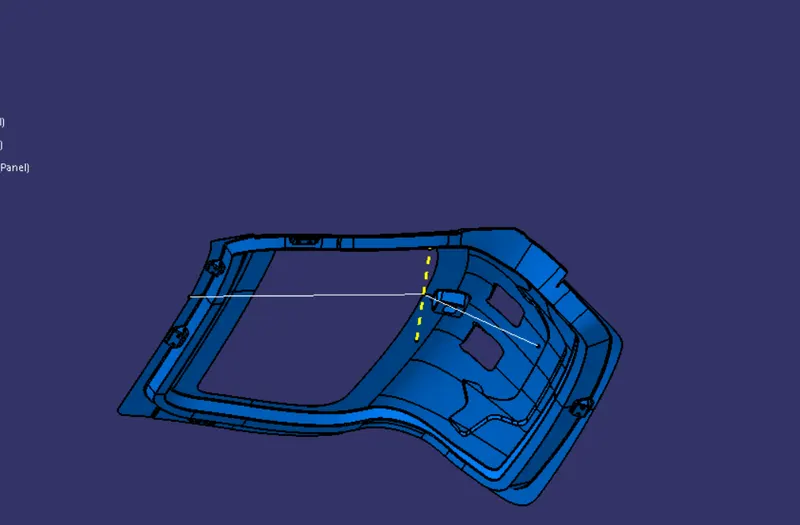
- Draw a line from left and right extremities almost parallel to the path of the surface along the unsymmetrical axis.
- Using the Derived lines tool, create a bsecting line as shown below:
- here we have created the tooling axis using bisecting method
-
Tooling axis creation
- The direction in which the mould open and closes is called the tooling axis direction.
- Check the connectivity of the surface and ensure there will be no gap between the surfaces and then define the tooling axis.
- While creating a tooling axis please ensure to give the tooling axis on a flat length surface or the surface which have a hole on it.
- Create a point on the middle of the base surface by using point on the surface command then create a intersection for the surface and extract the reference lines which will be helpful for creating the dummy tooling axis using the intersect method by creating a bisecting line..
- Use the line command and draw the lines which is aligned with the extracted lines and extended it to the required length.
Bisecting method
- Identify on which plane we have to do more operations and create the plane or axis on the component area define it on the dummy tooling axis direction.
- Intersect the class A surface with that plane then we will get a intersection sketch. Look for the profile (inclined line) which will create a problem and extract it then extending it by using line command.
- Then create a bisecting lines with reference to the lines we have extended and this will be our main tooling axis.
- In this case we have created tooling axis along with Y direction with reference to the base surface.
But in Our Project We Created Tooling Axis By Extracting The Surface and Drawing line by POINT - DIRECTION
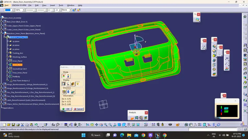
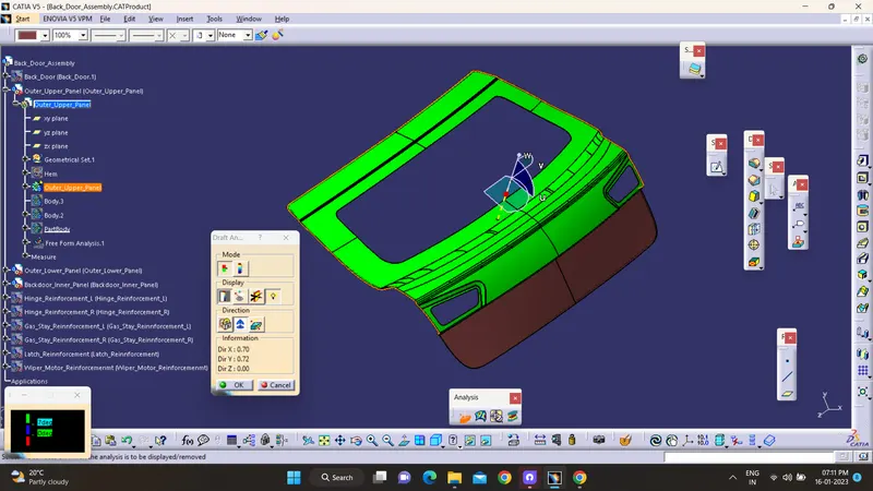
Draft analysis
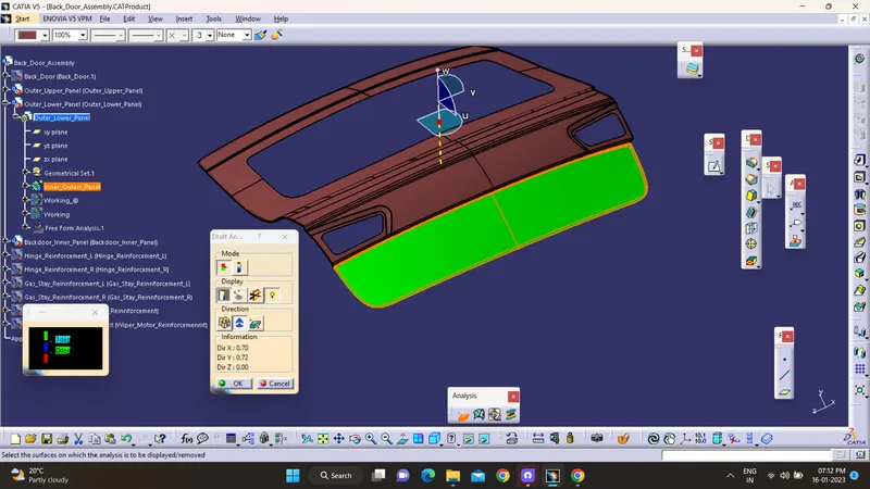
- Draft allows for the component to release from the mould, most parts or applications require a minimum of 0.5 to 1 degree draft angle and 7 dgree draft angle is widely used as per the norm.
- Change the material mode to customize mode before moving to the draft analysis.
- Insert –analysis-feature draft analysis
- Defining the draft direction Select draft analysis from the tool bar and click on the compass symbol and pull the compass from the right side top corner of the workbench and place it on the component where want to do the draft analysis. ‘W’ of the compass and tooling axis should be aligned on the same line.
- Once the compass is aligned with the tooling axis click on the lock symbol and drag on the surface we will get a wrong mark then select that point a table will appear it shows the draft value on the table we can adjust the draft value and analysis it for all the edges and surfaces.
- By clicking the on the surface and using the flipping tool we can assign the Flipping direction, the color of the surface change as per the flipping direction .
- Analysis under running point and move the mouse on the surface and it will show the details of the surface deg direct at each and every point of the surface.
Pre requisites before creating the tooling axis and performing draft analysis-
- Ensure that the Class A surface imported should be a single surface.
- This can be checked using the Boundary tool in the Operation Toolbar.
- If the surfaces are disassembled, join them using Join command which is also found in t
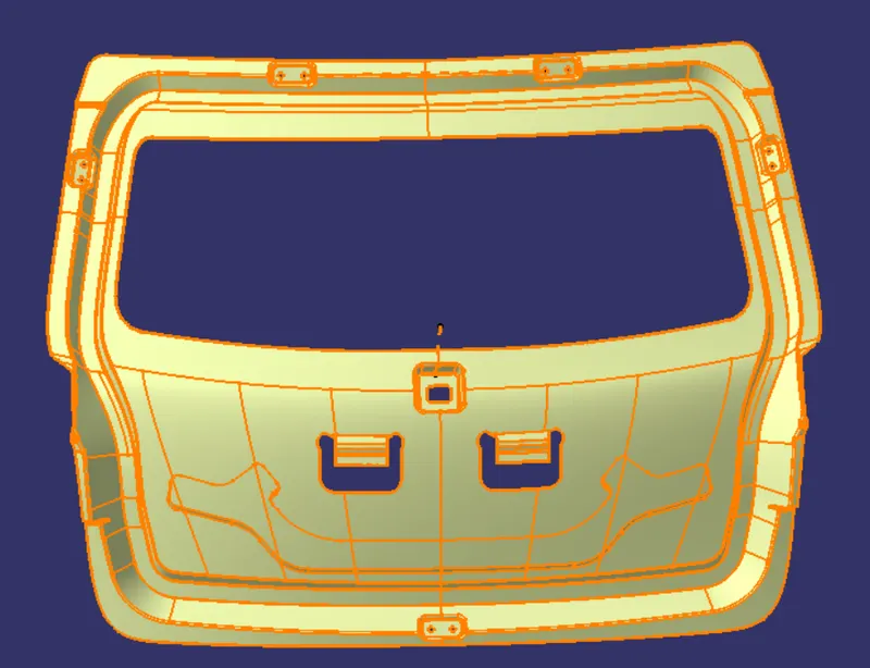
3. Creating Inner panel
- First offset the surface to a distance of 1.7mm, which will give the innerpanel surface position.
- Now the sealing flange for the inner panel has to be created.
- The seaing flange created by cuttng from the surface is shown below:
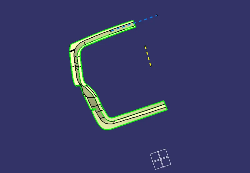
- In between, the tangent tensioning (Shape control) can be adjusted by modifying the surface using the Bridge curve tool.
- This flange has to be in a depth of 30 mm from the surface
- Now connect the flange with the surface using law extension w.r.t the tooling axis and proper draft given.
- Fillets has to be applied at each steps and check whether the surface is getting thickened or not.
- The next step is to create the other side which has to be connected with the sealing flange. ]
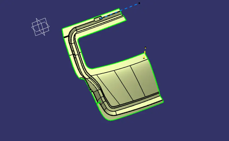
- A mastic sealent is used on the surface to connect the inner and outer panel with a gap of 5mm.
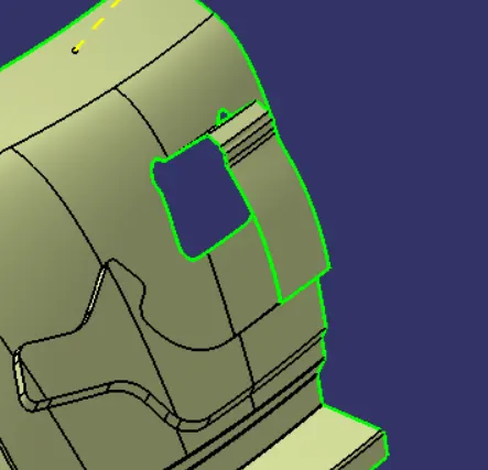
- Similarly connect the lower side of the surface by creating a surface and sew it all together.
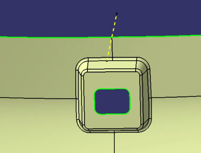
- Now, embosses has to be created for the Hinge, Gas stay, Latch & striker as well as the wiper motor areas.
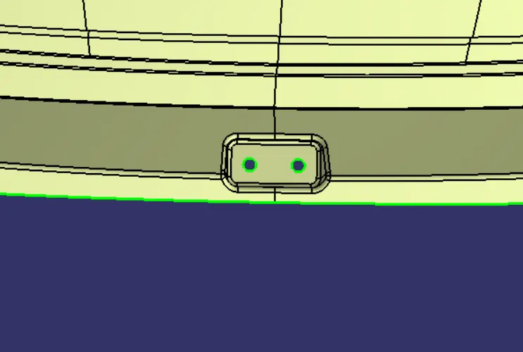
- The above latch emboss can be created with the help of drawing trajectory for opening/closing w.r.t the hinge axis.v
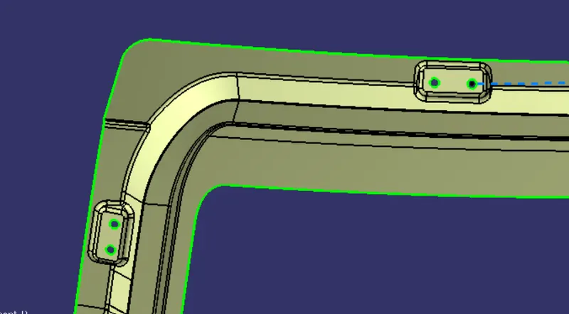
4. CREATING REINFORCEMENTS:
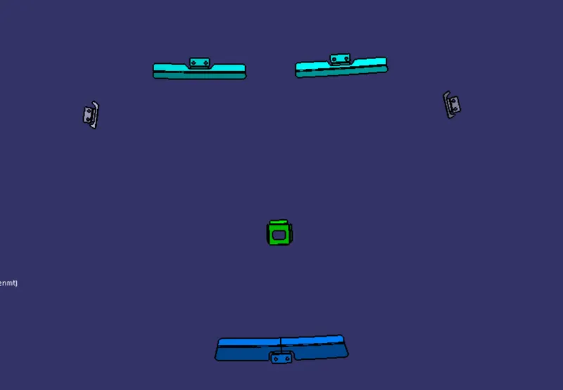
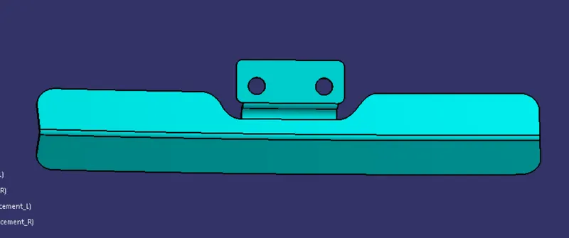
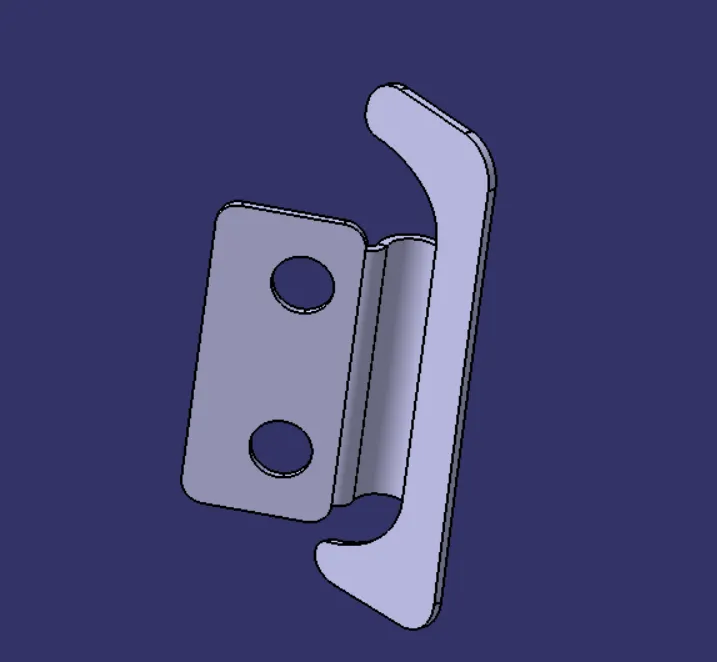
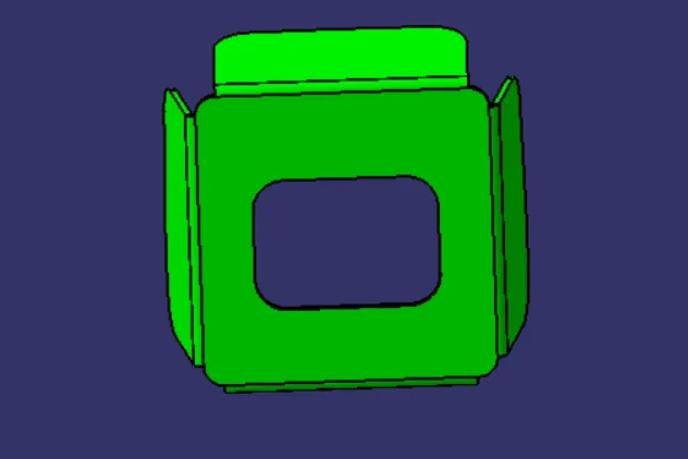
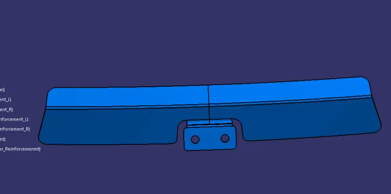
- The reinforcements can be directly offseted from the inner panel surface using the Wave geometry linker and trim it accordingly
- All reinforcements are shown below:
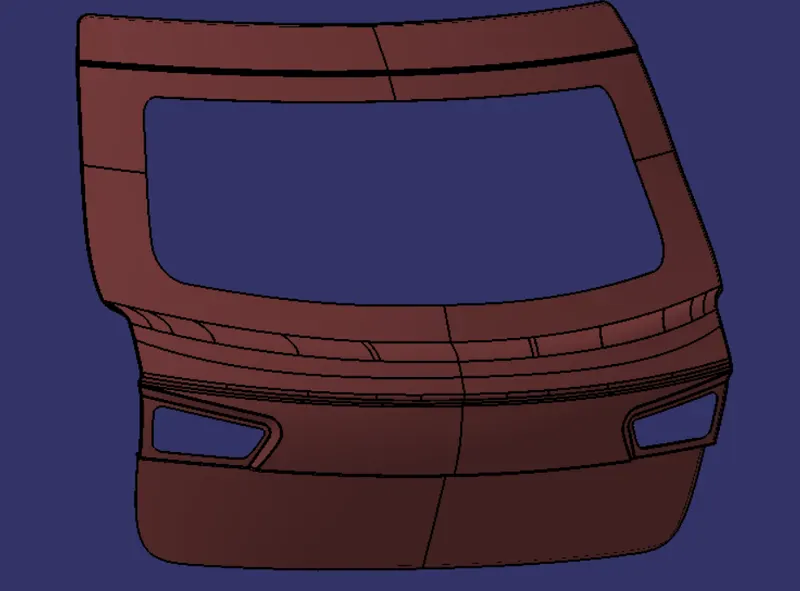
5. OUTER PANEL CREATION-UPPER :
- Offset the surface to a distance of 2.65mm so that 0.2mm of clearance can be given in between the surfaces.
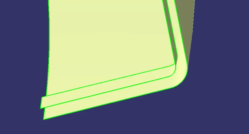
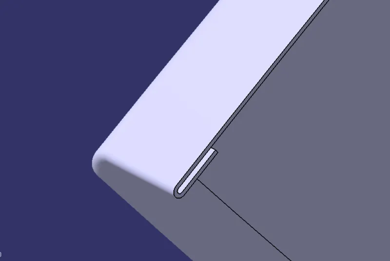
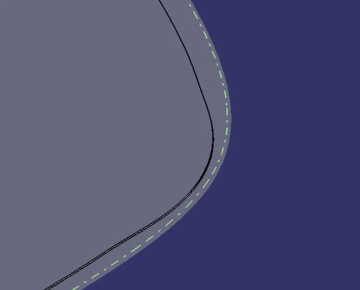
- Create the hem using the through curve mesh or swept tool in the surface panel. lso the surface must have tangent continuity.
- Reliefs has to be given in the corner areas for the easy manufacturability.
relif
Final Component
Draft Analysis
Upper outer panel
Lower outer panel
Inner panel