Design of backdoor
BACK DOOR
Aim
To develop the back door from the given class A surface with reinforcements and embosses by following appropriate design methodologies and by maintaining the draft angle for the tooling.
Introduction
Backdoor of the vehicle door are located next to the passenger seat which provides access to the luggage compartment. In the most of the cars, these backdoor are operated with the help of gas stay or power spindle which in turn reduces the effort required to lift the door.
Outer panels of back doors are divided into two parts, outer panel upper and outer panel lower. One end of the back door outer panel upper is in contact with the roof rail and the weather strip will cover the gap between them and the other side is in contact with body side outer. The outer panel lower is in contact with rear floor and body side outer. Weather strip is in contact with outer panel upper, outer panel lower, rear floor and roof, body side outer and which will close the gap between them. Outer panel upper and outer panel lower are joining together by spot welding method and required a minimum space of 8mm to do the operation.
Some of the engineering features and the points to be considered while designing the back door inner panels are Hinge reinforcement, Striker reinforcement, Gas stay top mounting/bottom mounting, Hinge axis, latch and striker point, trajectory, sealing flange, hinge area top / bottom, latch and strike actuators/ motor, wiper motor area, rear visibility, luggage area, Strength for rear crush.
Outer panels and Inner panels are joined together by means of Hemming, mastics and spot welding techniques.
Back doors are made up of materials such as aluminium or steel. Aluminium is weight less and required minimum radius and draft angle for tooling, casted part and it is costly compare to that of steel. So in recent years almost all the manufacturer’s are using aluminium as the material for BIW fixtures.
Manufacturing process of the back door
Stamping process
Metal stamping is a cold-forming process that makes use of dies and stamping presses to transform sheet metal into different shapes. Pieces of flat sheet metal, typically referred to as blanks, is fed into a sheet metal stamping press that uses a tool and die surface to form the metal into a new shape.
Metal stamping, also referred to as pressing, is a low-cost high-speed manufacturing process that can produce a high volume of identical metal components. Stamping operations are suitable for both short or long production runs, and be conducted with other metal forming operations, and may consist of one or more of a series of more specific processes or techniques, such as:
- Punching
- Blanking
- Embossing
- Coining
- Bending
- Flanging
- Punching and blanking refer to the use of a die to cut the material into specific forms. In punching operations, a scrap piece of material is removed as the punch enters the die, effectively leaving a hole in the work piece. Blanking, on the other hand, removes a work piece from the primary material, making that removed component the desired work piece or blank.
- Embossing is a process for creating either a raised or recessed design in sheet metal, by pressing the raw blank against a die that contains the desired shape, or by passing the material blank through a roller die.
- Coining is a bending technique wherein the work piece is stamped while placed between a die and the punch or press. This action causes the punch tip to penetrate the metal and results in accurate, repeatable bends. The deep penetration also relieves internal stresses in the metal work piece, resulting in no spring back effects.
- Bending refers to the general technique of forming metal into desired shapes such as L, U, or V-shaped profiles. The bending process for metal results in a plastic deformation which stresses above the yield point but below the tensile strength. Bending typically occurs around a single axis.
- Flanging is a process of introducing a flare or flange onto a metal work piece through the use of dies, presses, or specialized flanging machinery.
Metal stamping machines may do more than just stamping; they can cast, punch, cut and shape metal sheets. Machines can be programmed or computer numerically controlled (CNC) to offer high precision and repeatability for each stamped piece. Electrical discharge machining (EDM) and computer-aided design (CAD) programs ensure accuracy. Various tooling machines for the dies used in the stampings are available. Progressive, forming, compound, and carbide tooling perform specific stamping needs. Progressive dies can be used to create multiple pieces on a single piece simultaneously.
Manufacturing effects over spindle type and positioning
Position of hinge –outside/inside backdoor
Gas stay socket -body mounting / back door mounting
Force affecting areas –lower on inner panel areas
Load case analysis on back door
- Bend test- Forces are applied at the center of the constrained doors and check for nominal value to come back to its original position.
- Torsion test- Constrain hinges, latch and striker and apply force on each end in reverse direction and check for the behavior of the door and how it regains the original shape.
- Abuse case-This test is done for check how the material behaves and regain its original shape when there is over-slam or hanging force acting when the door is in open condition.
- Dent test- To check whether the material is come back to its original position once the force is released.
- Assembly load case- This is to determine how much force should be given to the body during the vehicle assemble and how the door is withstanding them.
- Endurance limit- This test is conduct by opening and closing the door for ‘n’ number of cycles and what will be the final condition after the operation.
Input received
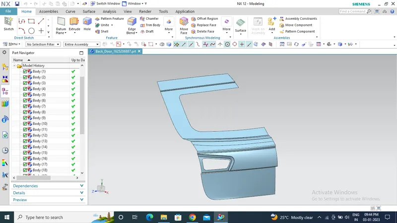
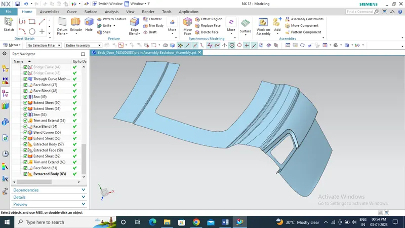
Improved class A surface and adding flanges for spot welding the upper and lower outer panels
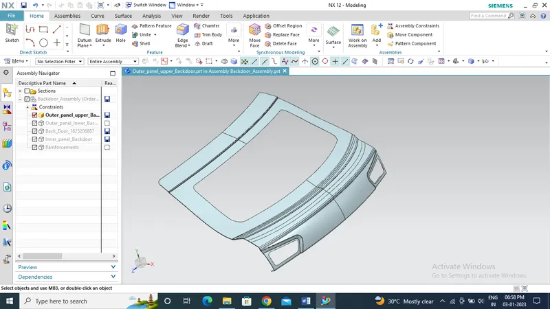
Outer Panel upper
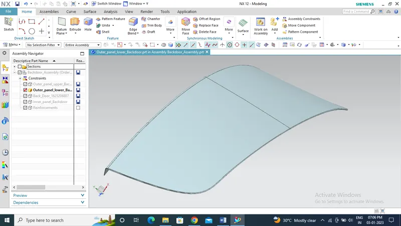
Outer panel Lower
Tooling axis
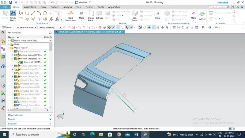
Developing the inner panels and adding engineering features such as reinforcements, embosses, provision cutouts, positioning the hinge, striker and wiper motor axis.
Sealing flange
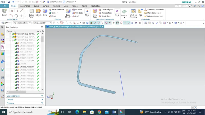
Sealing flange with connecting flange
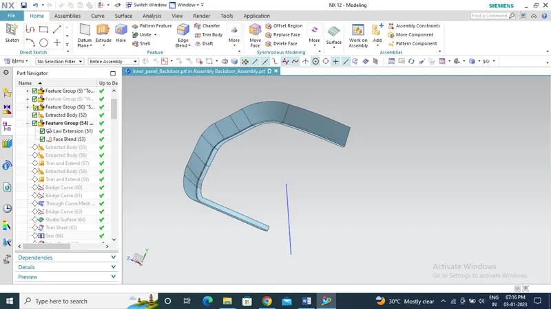
Hinge emboss
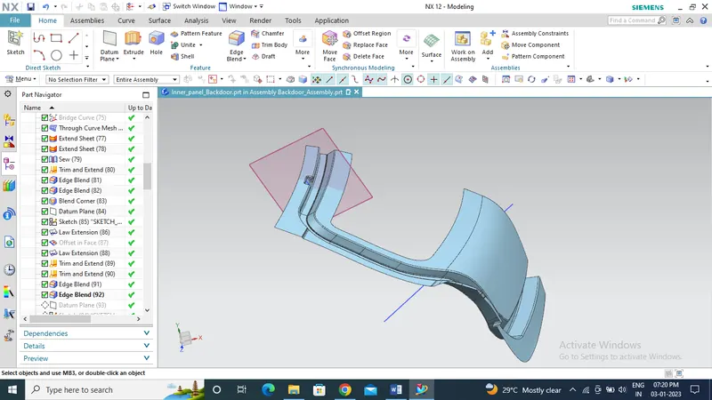
Gas stay emboss
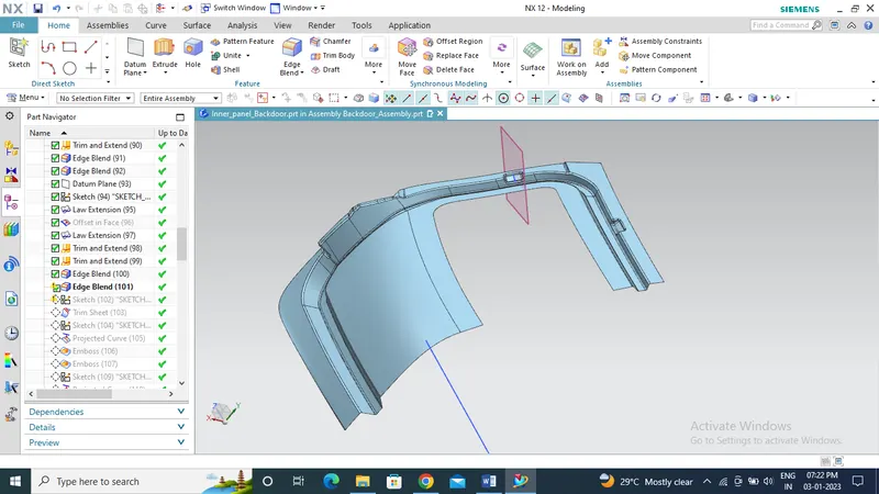
Emboss
Emboss represents the union of several souls that give life to a singular product. Sheet metal embossing is a stamping process for producing raised or sunken designs or relief in sheet metal. This process can be made by means of matched male and female roller dies, or by passing sheet or a strip of metal between rolls of the desired pattern.
Embossed steel is ideal for customers looking to add aesthetic touches or functional improvements to a product. Embossing can help disperse liquid more effectively, reduce friction and static, bolster metal panel stiffness and rigidity, obscure dirt and blemishes for a consistent appearance, increase metal surface area for acoustic or heat transfer and improve traction, embossed panels have greater spanning abilities.
In the hood design emboss are provided to strengthen the hood assembly and divert the impact force acting during a crash to the edges and towards the hinges there by minimizing the effect of crash to the passengers and pedestrians.
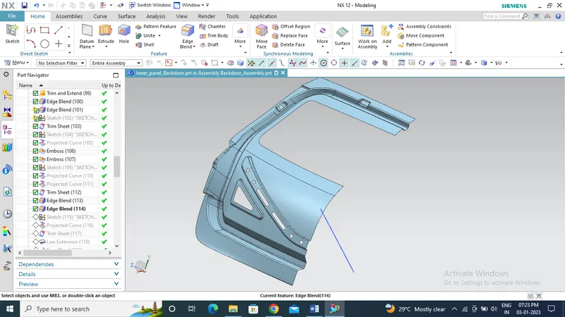
Mastic data
Mastic adhesive was developed specifically to bond exterior automotive panels to the vehicle’s inner panel structure, such as on roofs, doors, and hoods. This one‐component synthetic rubber sealer remains elastic after curing to reduce panel flapping and to prevent panel distortion.
Thinner automobile panels help reduce vehicle weight, but are prone to flutter and excessive in‐cabin noise due to aerodynamic effects at highway speed. Mastic adhesive is suitable for a variety of metals and is an excellent choice for assemblies where aluminum and other alloys are used which fill gaps and channels within the auto body that are vulnerable to wind, thereby blocking the flow of air that can generate unpleasant noise at driving speeds.
A standard mastic adhesive used for hood assembly should expand up to 5mm after applying heat and have a coverage of 80mm from the center thus the positioning of mastic can be determined and give provisions for them on the hood inner panel.
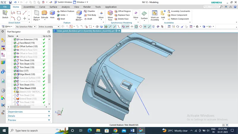
Flanges for the mastic
Latch Trajectory
Latch trajectory is the position where the latch is in exact contact with the striker which is fixed to the inner panel of the back door with respect to the position of hinges. The position can be determined by drawing a circle by taking the center point as the midpoint of hinges axis point which will concentric with each other. Then a tangent line was created with respect to the circle which starts from the inclined line is drawn through the circle which ends on the circumference of the circle at an angle.
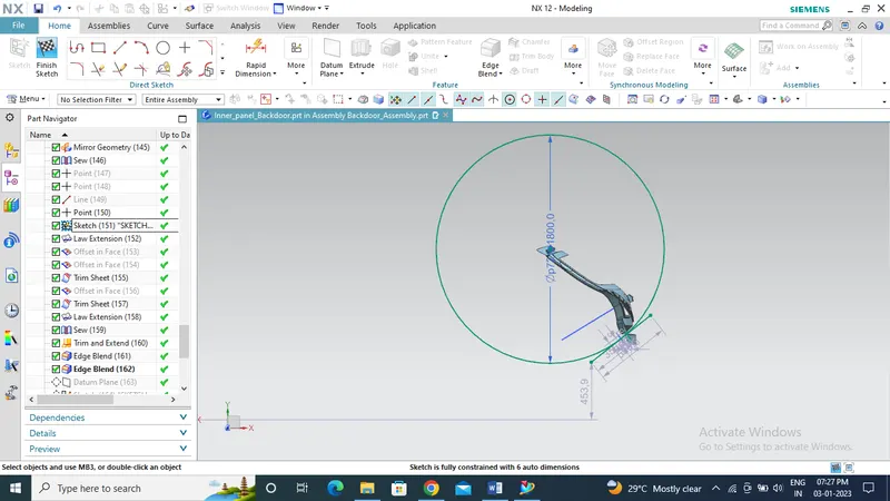
Latch and striker trajectory
Wiper motor mounting area
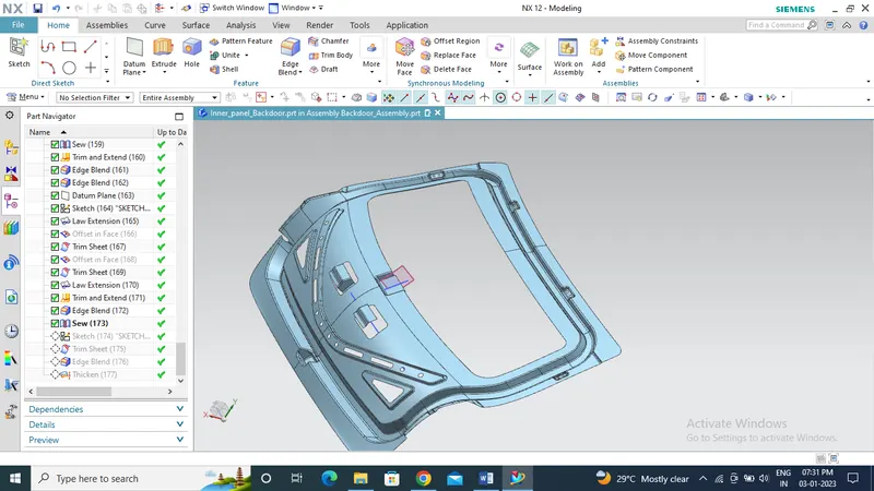
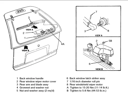
Wiper motor mounting details
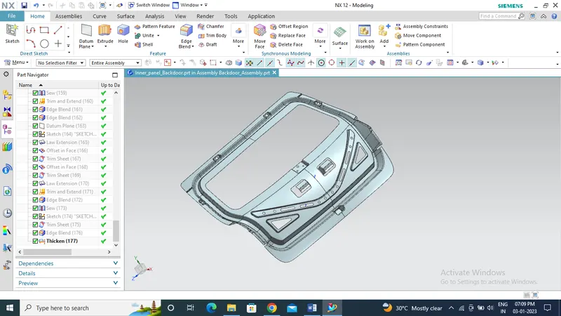
Thickened part of Inner panel
Reinforcement for Hinges, gas stay, latch and striker, wiper motor on inner panel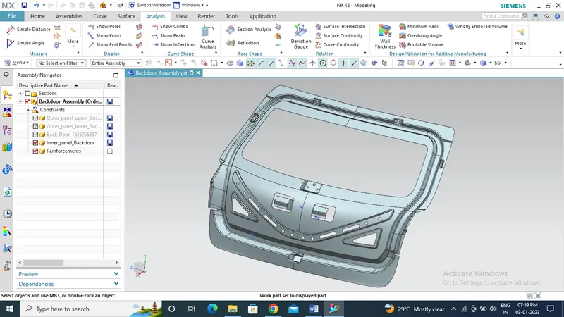
Hemming
Hemming is a forming operation in which the edges of the sheet are folded or folded over another part in order to achieve a tight fit. Normally hemming operations are used to connect parts together, to improve the appearance of a part and to reinforce part edges.
In car part production, hemming is used in assembly as a secondary operation after deep drawing, trimming and flanging operations to join two sheet metal parts (outer and inner) together. Typical parts for this type of assembly are hoods, doors, trunk lids and fenders.
The accuracy of the hemming operation is very important since it affects the appearance of the surface and surface quality. Material deformations, which occur during the hemming process, can lead to dimensional variations and other defects in parts. Typical hemming defects are splits or wrinkles in the flange, material overlaps in the corner areas or material roll-in. This is why it is important to use simulation tools in order to, on the one hand, better understand the hemming process and, on the other hand, significantly reduce the number of “trial and error” loops during tryout und production.
There are various types of hemming operations, Conventional die hemming & Roll hemming
a) In conventional die hemming, the flange is folded over the entire length with a hemming tool.
b) Roll hemming is carried out incrementally with a hemming roller. An industrial robot guides the hemming roller and forms the flange. Roll hemming operation can also be divided into several pre-hemming and final hemming process steps. Roll hemming is very flexible to use and tool costs are significantly lower as compared to those of conventional die hemming. However, the cycle times are much higher since the hemming is realized using a hemming roller which follows a defined path.
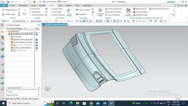
Inner and outer panel after hemming
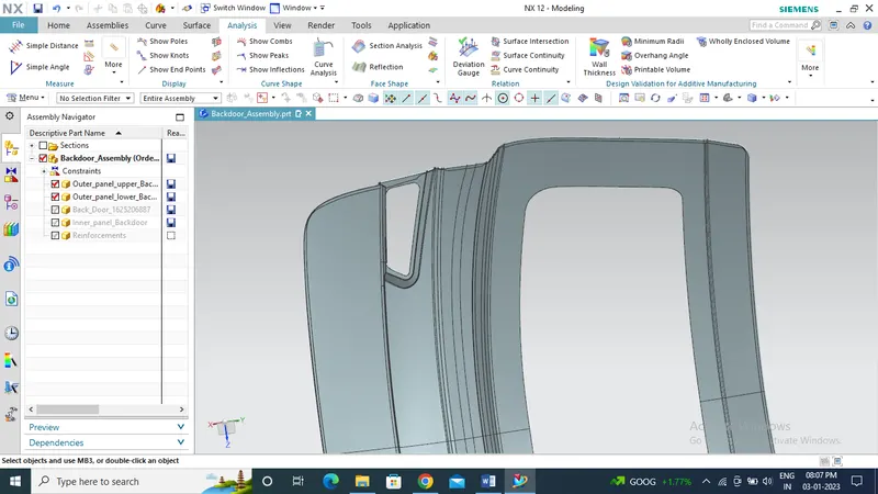
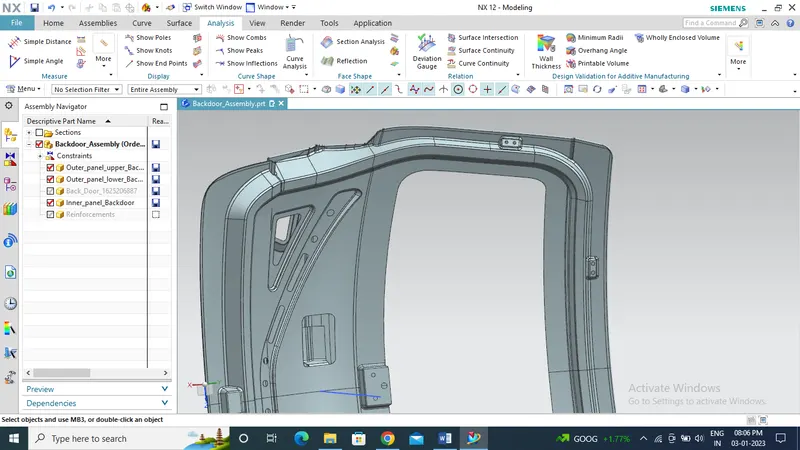
Draft analysis on Hinge emboss and gas stay emboss
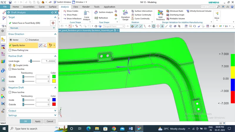
Draft analysis on latch and striker area and wiper motor mounting
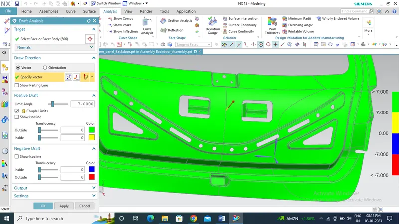
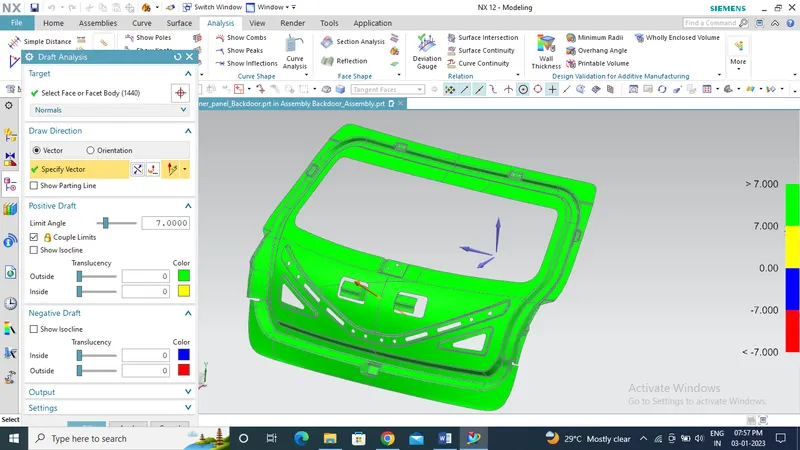
Draft analysis on inner panel
Conclusion
Thus we have design and developed the back door with all engineering features by following the design guidelines and maintained clear draft for tooling and manufacturing standards.