Design of backdoor
| BACK DOOR DESIGN |
AIM:
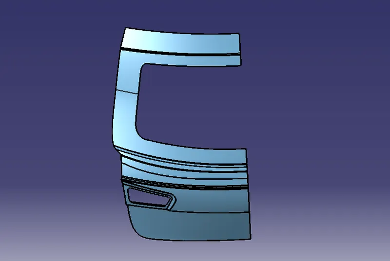
The objective of this project is to design a BIW Back Door of a car with Inner Panel, Outer Panel and the Reinforcements for the Hinges, Gas stay, Wiper Motor and Latch by following the engineering standards. The Inner Panel must be subjected to Draft Analysis for verifying whether it satisfies the Deep Drawing requirements for the tooling direction created.
Input
| THEORY |
HATCH BACK
The hatchback is a vehicle type which has a characteristic separate opening or door that provides access to the cargo area or boot. This door is known as ‘hatch’. And thus, the manufacturers term this category of cars as a ‘hatchback’. Although it is different than a coupe.
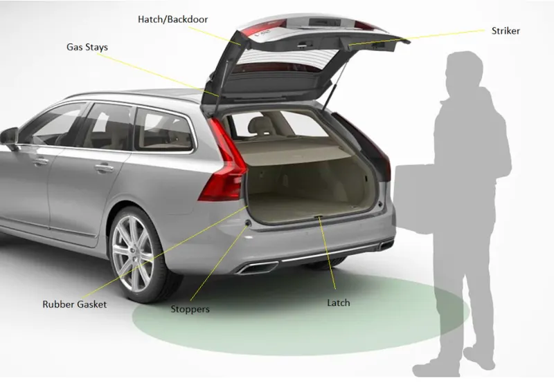 |
The hatch in a Hatchback incorporates the rear glass. This door generally hinges at the top end of the rear body panel. Thus, after opening the entire door flips upward and provides access to the cargo area.
Because of the ease of access, people prefer the hatchbacks when they need to transport a large quantity of material. It is also useful when they need to open/close the door frequently to keep/remove the material from the car. Some hatchback vehicles also provide the facility to fold the rear seats which adds significantly to the storage space.
In general, these cars are either available as three door or five door versions. Three door hatchback consists of two doors for the passenger entry and third for the luggage. Similarly, in five-door version, it is four plus one combination. It has four doors for the passengers and one for keeping/removing the luggage.
ADVANTAGES OF HATCH BACK
These types of cars are very popular in many parts of Europe because of their compact dimensions and large storage space. Maruti 800 is the legendary entry-level hatchback in India which crossed sales figure of 2.5 million units since its launch. Similarly, Tata Indica launched by Tata Motors received a record 115,000 bookings during the first phase of its launch.
The only significant disadvantage of the hatch segment is that one can easily see the material loaded in the storage area as the boot lid incorporates a glass window. Suzuki Swift, Ford Fiesta, and Hyundai i20 are some of the most popular hatchbacks in the world.
BACK DOOR
The back door is a hinged door/tailgate at the rear of the vehicle. It may be used for loading and unloading cargo, or to get passengers in and out, in case there are seats present at the rear. The back door comprises of certain components which form the back door assembly together.
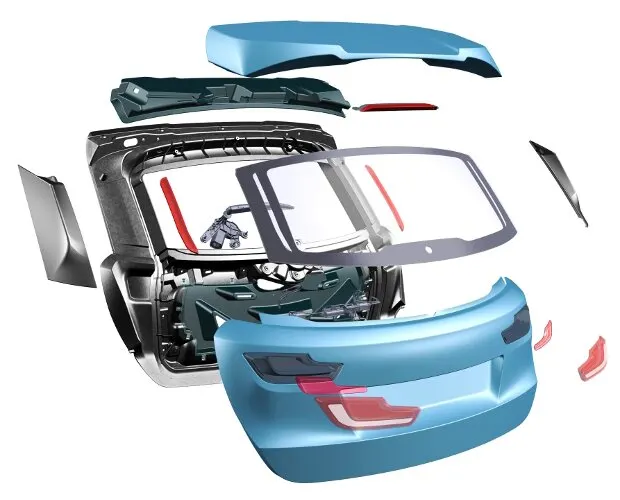 |
The Back Door of a car is the rear most part of the vehicle which gives access to the trunk space of the vehicle. The rear door also supports the reinforcements and added weights of the Wiper Motor, Gas Stay, Tail Lamp and Latch and Striker. The back door is usually made of an inner panel and 2 or 3 separate inner panels joined together by hemming or spot welding wherever necessary. The material used for the door manufacturing depends on the budget and performance of the vehicle. Mostly Aluminium and Steel will be used whereas low budget vehicle use Steel which makes the manufacturing process easy and cost efficient since it follows the Stamping of Moulds. But Aluminium were used for high budget cars since it increases the manufacturing cost since the Aluminium parts will be mostly die casted hence it has variable thickness which reduces the requirement of reinforcements but improves the performance of the car rapidly since Aluminium is not heavy as steel.
Functions of the Backdoor:
- It protects the occupants and luggage from getting damaged.
- It houses assembly of tail lamps, wiper motor and other components.
- It serves as entry and exit point for luggage/passengers.
- It houses windshield glass which helps in rear visibility.
- Parking sensors, rear view camera are mounted on it.
| TYPES |
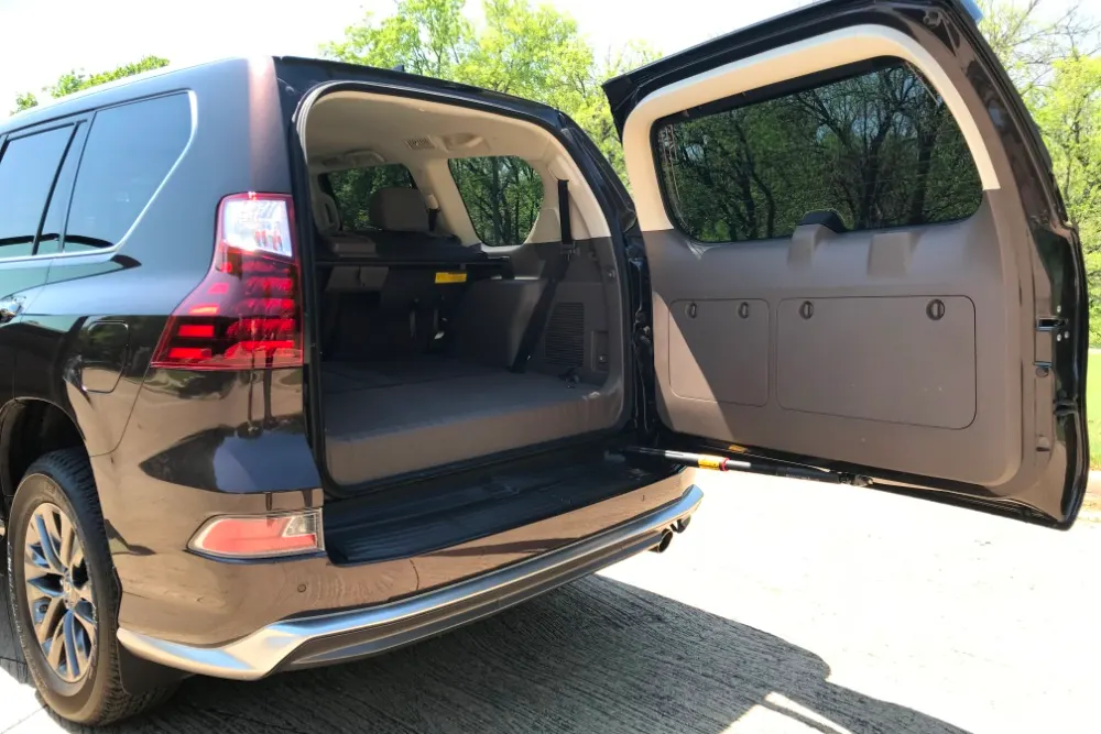
- Top mounted
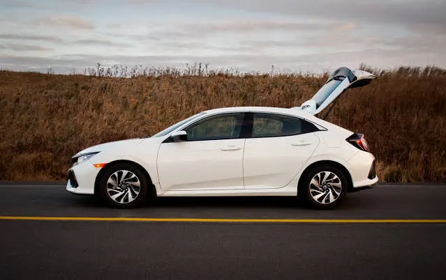
These type of back doors are used in a station wagon, pickup truck and some other sports utility vehicles. Today’s modern cars use top mounted tailgating systems which are both powered and also gas stay supported. These tailgates provide greater rear visibility compared to other types.
 |
- Side mounted
It is generally used in van type MPVs, SUVs, pickup truck vehicles. These side mounted door/barn doors are a lot easier compared to top mounted ones. These doors are generally small in size and can be easily accessed. These doors are more convenient for the goods handlers carrying lengthy objects, long pipes where one door is kept open. It also saves accidental head impacts. It is a lot easier to load /unload things in vehicles having side-mounted doors.
 |
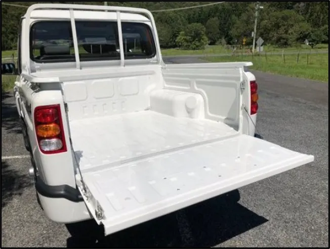
- Bottom mounted
Bottom type or split type backdoor system is used in estate type cars, pickup trucks and some luxury SUVs. These are most convenient type of backdoor in which the bottom split is used as a support or even as a table for the touring people.
 |
| FUNCTIONS |
Kinematics and Stop Systems:
The liftgate hinges are embedded in the rear roof cross member, closer to the side roof end than to the roof center line. They can be single joint hinges with fixed axis, each half hinge being fastened by one or two screws, when the roof has a small curvature. If the liftgate to roof surface border line has a relevant curvature, that kind of hinge cannot be used, because the liftgate rotation could cause interference with the roof. To avoid this inconvenience, an articulated quadrilateral can be used (also known as pantograph hinge), the rotation center of which moves during liftgate motion (Fig. 4.1). These hinges feature a higher obstruction than the simple hinges and therefore are usually located close to the side liftgate end.
Examples of liftgate single joint three screws hinge (A) and pantograph hinge (B)
Regarding the liftgate and trunk lid lift and support at rest, traditional springs can be used as well as torsion bars or gas struts which, despite their cost and thermal sensitivity, are the ones mainly used today. It is important to position the liftgate gas springs rods below, so that the oil in the cylinder can always keep the gaskets wet so as to maintain the internal pressure.
Types of mechanisms for Rear Door:
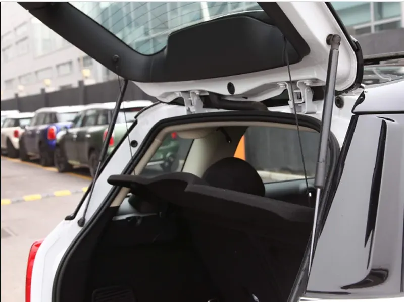
Gas stays:
Gas stay types backdoor/liftgate/tailgate is an ideal and most commonly used tailgate mechanism from lower segment car to luxury car segment. The ideal components of tailgate consist of a hinge, door, gas stay and some rubber beadings for sealing of door.
 |
Powered lift system:
Power trunk lid system is another sophisticated way of trunk/liftgate opening mechanism which is to automatically open and close of the trunk/liftgate and release of the latch by the touch of a button.
 |
| MATERIAL SELECTION |
The selection of material plays a major role in determining the overall weight of the back door. The common materials used are Steel & Aluminum. The density of Steel is higher than Aluminum thus adding more weight to the door. The material used in the manufacturing of the backdoor depends upon the budget of the car, most low cost vehicles use steel as it is cheaper compared to Aluminium. Another aspect to be noted is that, if casted Aluminum parts are used instead of deep drawn steel parts there is no need of reinforcements and the overall weight of the car is reduced by approximately 5-10kg thus increasing the performance of the vehicle. Also the draft angle for casted parts is around 3 degrees while for deep drawn parts is around 7-10 degrees which helps in increasing the luggage/ cabin space.
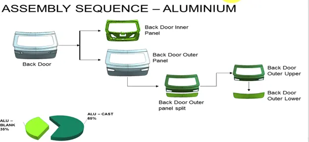 |
Fig. above shows possible no. of parts in aluminium backdoor
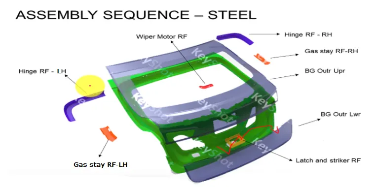 |
Fig. above shows possible no. of parts in Steel backdoor
Aluminium and Steel comparative informations:
| Aluminium | Steel | |
| Parts | Parts are casted | Parts are stamped |
| Reinforcements | Reinforcements can be neglected | Reinforcements are necessary |
| Thickness | Thickness can be varied | Thickness should be uniform |
| Weight | Lighter in weight | heavier in weight |
| Cost | Costly as compared to Steel | Cheap as compared to Aluminium |
| No. Of components | Less No. of components | More No. of components |
| STAMPING OPERATIONS ON SHEETMETAL |
The process of turning sheets of material into a useful part or component is called sheet metal stamping. The metal is fed into a press, Where the stamping tool also known as a die, creates the desired shape. The die is pressed into or through the metal with tremendous force. The force used in the process is meaasured in tonnes. Except for some specialized process sheet metal stamping doesn't use heat. Instead, it is done with a cold forming technique. Even though no heat is used, the part can come out hot because of the friction that's created between the die from the force of the press.
Metal stamping, also referred to as pressing, is a low-cost high-speed manufacturing process that can produce a high volume of identical metal components. Stamping operations are suitable for both short or long production runs, and be conducted with other metal forming operations.
Drawing Operations
It is the process of fabricating thin-walled hollows or vessel-shaped pieces out of sheet metal. It can be classified into two groups:
Shallow drawing – the item to be drawn has a length that is less than its width. Pans, tubes, and cams are instances of drawing.
Deep drawing – the object to be drawn has a depth that is greater than its breadth.
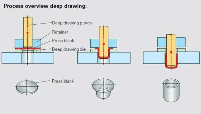
The metal deep drawing process is an effective method of manufacturing of cups, cans and other similar deep drawing products. The deep drawings having two main categories.
- First- stage drawing: The blank shape of metal is placed on the die and contact with the punch. When the metal specimen is flat piece of sheet metal used in forming and finish the product. Initially the punch moves in downward direction. The outer rim of blank is subjected to pure radial drawing (drawing toward in vertical axes) between die and blank metal. The metal become a bend and sliding over die and also stretched between die and punch. The metal in vicinity of punch head and contact with it bend and slide over radii and stretch over punch head.
- Redrawing: The components drawn from first stage again it is redrawn convert into more depth to form a cup shape in the die and punch. The second stage of drawing is called as redrawing.
EMBOSSING:
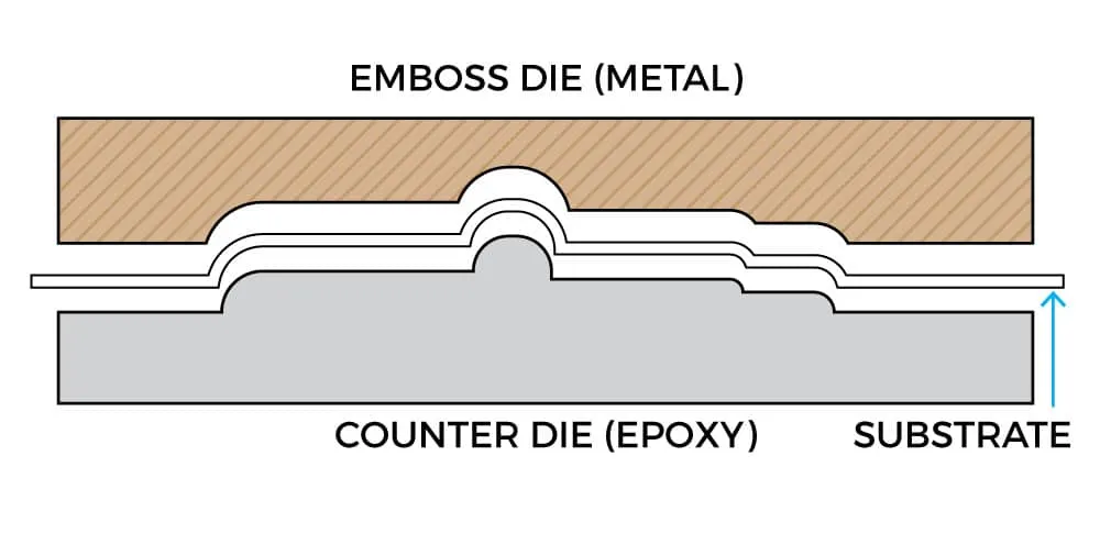
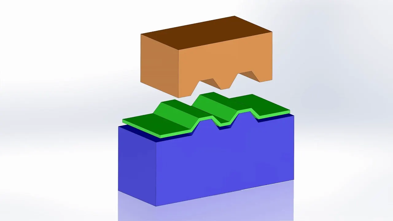
Embossing is a metal forming process for producing raised or sunken designs or relief in sheet materials by means of matched male and female roller dies, theoretically with no change in metal thickness or by-passing sheet or a strip of metal between rolls of the desired pattern. Metal sheet is drawn through the male and female roller dies producing a pattern or design on the metal sheet. Depending on the roller dies used, different patterns can be produced on the metal sheet.
Materials commonly used in the metal embossing process include:
- Aluminum alloys
- Steel alloys
- Zinc
- Copper
- Galvanized steel
- Brass
- Cold rolled steel
Blanking:
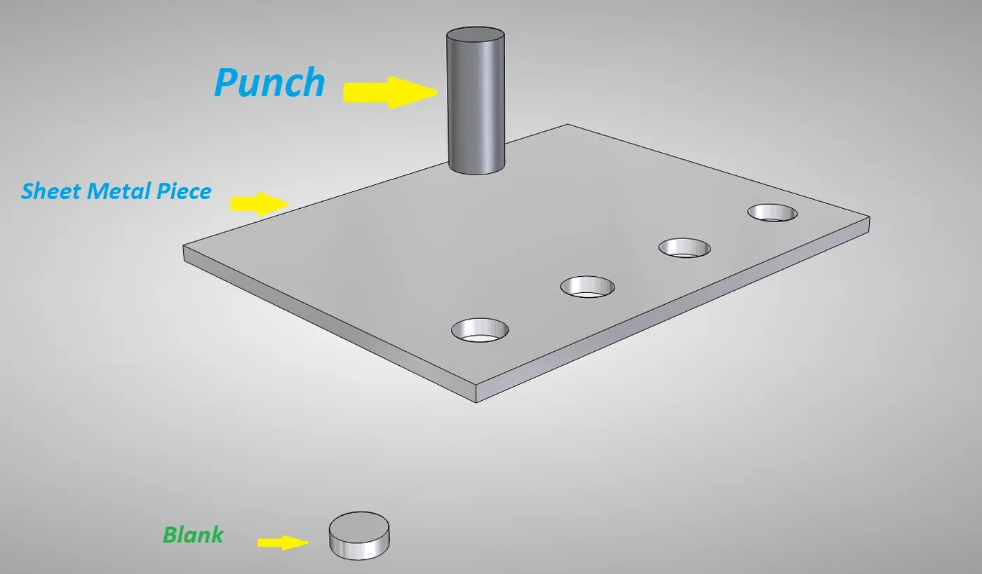
Blanking is the process of producing flat pieces from sheet metal. Only a small amount of sheet metal will be processed as a finished product or part over the larger sheet area in the blanking process. In this process, enough residue will remain. This process is done with the help of punch and die.
Punching:
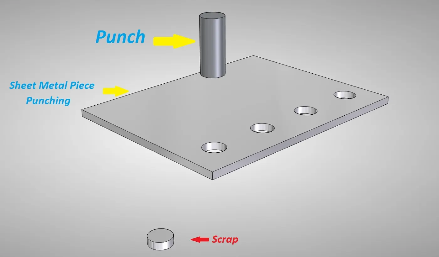
The punching operation is vice versa to blanking. In this operation, extra (scrape) material removes from the raw sheet. This operation also performed with the help of die and punch. But here the punch removes scrap.
Piercing:
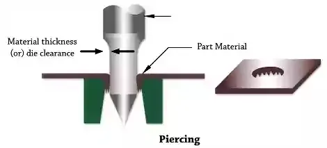
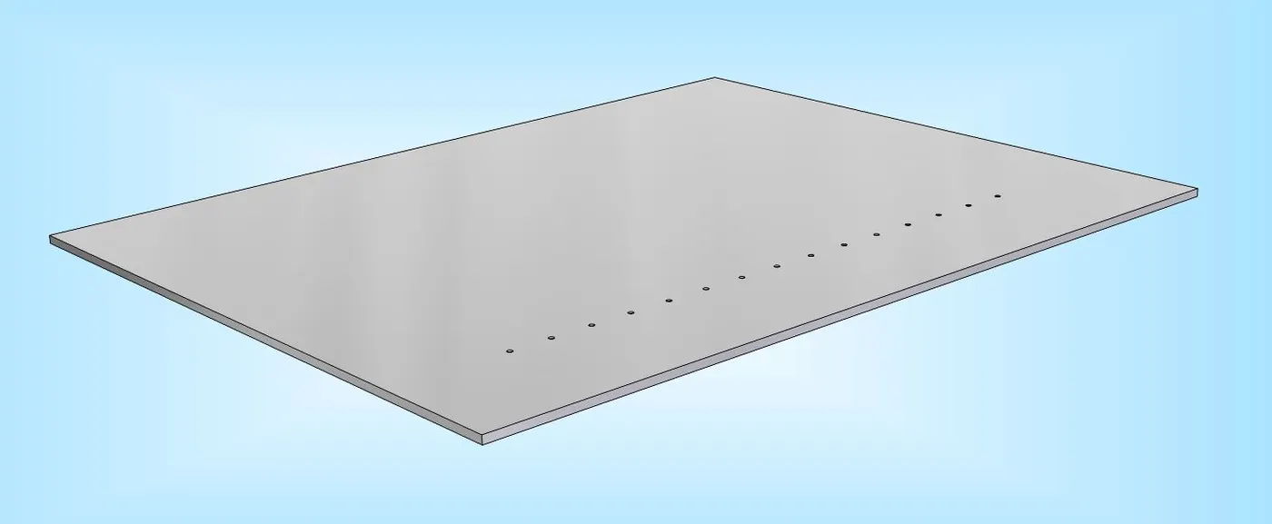
The word piercing means pinning any tool in the workpiece or sheet for creating circular or other shaped holes. Almost no scrape will be created in this operation. Creating a hole in paper using a pen or any sharp tool is also known as piercing. The piercing operation for sheet metal is also similar. For this operation, a blanking punch is used.
HEMMING
Hemming is a forming operation in which the edges of the sheet are folded or folded over another part in order to achieve a tight fit. Normally hemming operations are used to connect parts together, to improve the appearance of a part and to reinforce part edges.
In car part production, hemming is used in assembly as a secondary operation after deep drawing, trimming and flanging operations to join two sheet metal parts (outer and inner) together. Typical parts for this type of assembly are hoods, doors, trunk lids and fenders.
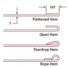
There are various types of hemming operations:
- Conventional die hemming: In conventional die hemming, the flange is folded over the entire length with a hemming tool.
- Roll hemming: In roll hemming, the hemming roller is guided by an industrial robot to form the flange.

Open Hem: A Hem has a full round feature and a return flange. In open hem bend angle is equal to 180 degrees.
Tear drop Hem: In tear drop hem the bend angle is greater than 180 degrees.
Closed Hem: Hems without any inside radius are called as closed hem. Closed hems are not recommended if the hem geometry is to be painted or if the material used is SST or Aluminium.
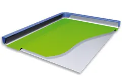
RELIEF ON CORNERS:
Notching operation is to cut out a portion of the sheet from its sides. And in semi notching operation metal cutting out from inside of the sheet. Sometimes, notches applied for stress relieving during the bending. So, notches created before the bending operations.
| JOINING MECHANISM |
SPOT WELDING
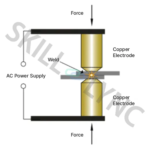
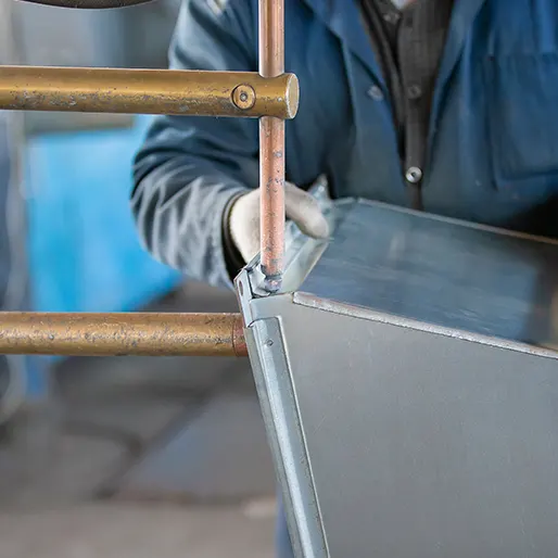
Also called Resistance Spot Welding, spot welding continues to be the main choice of joining processes in the body shop ( it constitutes close to 40% of all joining processes).
- It is a solid-state welding method and is used for joining overlapping sheet metals in projects where strength and durability are not pressing.
- Workpieces are held together under the force exerted by electrodes.
- Typically, the sheets are of the order the 0.3 to 6 mm thickness.
- The process uses two shaped copper alloy electrodes to concentrate welding current into a small "spot" and to simultaneously clamp the sheets. This forces the large current through the spot, which will melt the metal and form the weld.
- Spot welding has fewer applications and tends to harden and warp workpiece materials.
- Low-carbon steel is the most suitable material for spot welding.
ADVANTAGES
- Time-saving compared to TIG or MIG welding.
- Very suitable for high volume & automated production.
- It does not require grinding after welding (to remove slag formation).
- Minimal material distortion.
- Non-consumable electrode, unlike MIG Welding.
- No slag formation after welding.
ARC WELDING
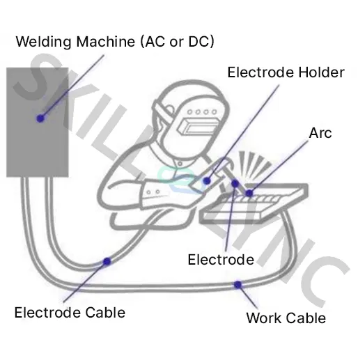
Arc welding is one of the most prominent types of welding. Arc processes involve using the concentrated heat of an electric arc to join metal materials (Fusion welding)
- The arc can be either manually or mechanically guided along the line of the join, while the electrode either simply carries the current or conducts the current and melts into the weld pool at the same time to supply filler metal to the
- Since the metals react chemically to oxygen and nitrogen in the air when heated to high temperatures by the arc, protective shielding gas or slag is used to minimize the contact of the molten metal with the air. Once cooled, the molten metals solidify to form a metallurgical bond.
METAL INERT GAS WELDING
MIG Welding is the most widely used arc welding technique in BIW joining. Aluminium parts have been largely joined by means of MIG (Metal Inert Gas) welding in lightweight car manufacturing.
This technique is principally used to make joints between castings, extruded sections, and sheet-metal parts.
MIG welders use a tool called a spool gun, which feeds a spooled wire electrode at a selected speed. The gun also emits a shielding gas as it lays the weld. This gas protects the weld area from atmospheric gases such as nitrogen and oxygen, which can cause problems if they come in contact with the electrode, the arc, or the welding metal.
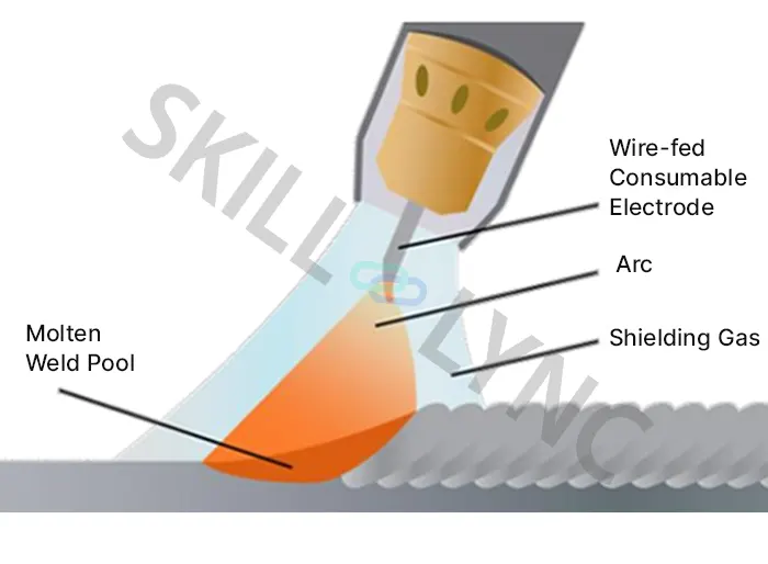
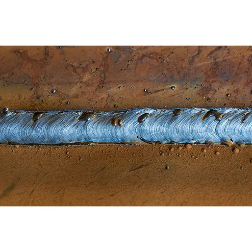
The final result of an optimal MIG Welding process
ADVANTAGES
- High-strength weld with a great appearance
- Little need for sanding or cleaning
- Relatively quicker process due to operability at a continuous rate due to the use of shielding.
- MIG welding can be used on any metal surface and can weld materials as thin as 26 gauge.
LASER BRAZING
- Welding vs Brazing
A brazed joint is made in a completely different manner from a welded joint. Brazing does not melt the base metals since the temperature is invariably lower than the melting points of the base metals. Brazing temperatures are significantly lower than welding temperatures for the same base metals, using less energy.
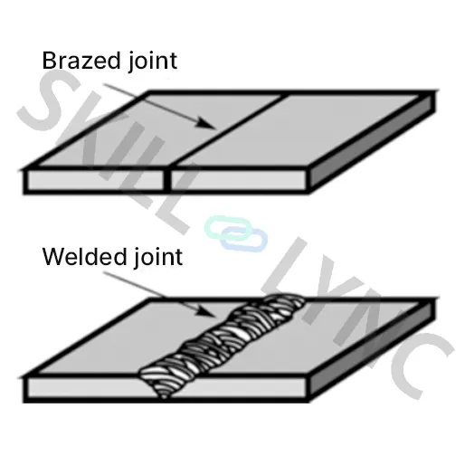
A brazed joint has a smooth, favourable appearance compared to a welded joint and reduced cost since there is no need to perform any finishing operations after Brazing is performed.
- Laser Brazing or Laser Soldering is a metal-joining process in which two or more metal items are joined together by melting and flowing a filler metal into the joint, the filler metal having a lower melting point than the adjoining metal.
- The filler material, typically a wire with a diameter of 1.0 mm, is fed to the process. The laser beam melts the wire, and the melt penetrates the gaps in the joint and wets the joint surfaces. The filler solidifies and forms a smooth joint. The filler wire can be preheated to increase the processing speed.
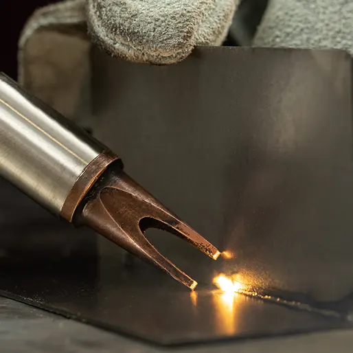
- Compared to laser welding or spot welding, laser brazing has improved geometrical tolerances and improves the joint's aesthetics.
- The consumer gets a lighter, quieter, stiffer, and safer car as the final that doesn’t have extra plastic parts.
CLINCHING
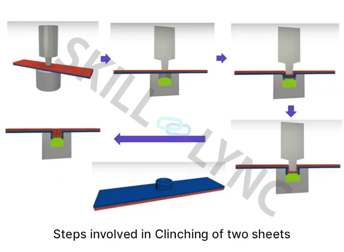
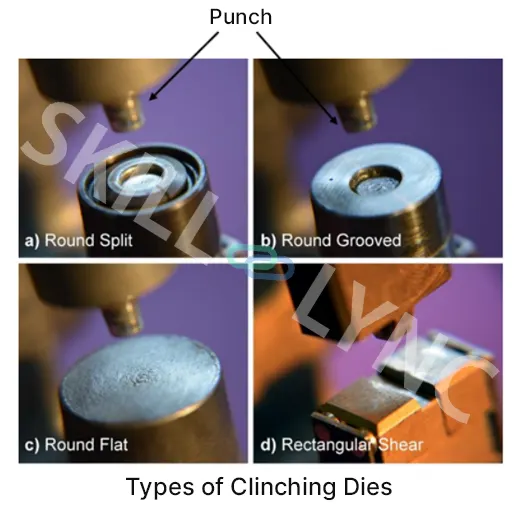
- Clinching(press-joining) is a bulk-sheet metal-forming process for joining thin metal sheets without additional components, using special tools to plastically form an interlock between two or more sheets.
- The process is generally performed at room temperature, but in some special cases, the sheets can be pre-heated to improve the material ductility and thereby avoid the formation of cracks during the process.
Advantages
- Riveting without rivets
- Fast, clean, and easy joining process
- High static and dynamic strength
- Energy savings since it does not require electricity
- No contamination of workpieces
- Used widely in the automotive industry, where it often replaces spot welding.
| DESIGN CONSIDERATIONS |
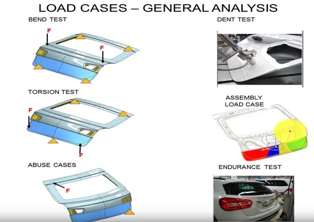
- visibility criteria through the rear glass while designing the sealing flange.
- Hinge positions.
- gas stay positions
- viper motor mounting and reinforcements
- Enough space ssjoulf be provided for harness routing and ease of accessibility
- latch and striker and its position based on trajectory
- position and orientation of latch-striker should be perpendicular to the hinge axis.
- shape of sealing flange
- the shape of the inner panel and its thickness affects in boot space.
- reinforcements to be provided at the hinge, gas stay region.
- Embosses creation and direction towards hinges.
- Drain holes to be provided (as the commodity undergoes electrolytic dipping and paint process).
- The minimum radius of bending to avoid material failure during stamping operation.
- Hemming Relaxation at bends.
 |
|
DESIGN METHODOLOGY |
|
|
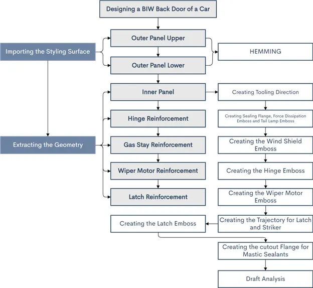 |
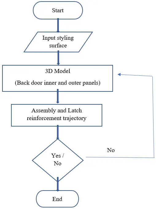
| DESIGN PROCEDURES |
THICKNESS REQUIREMENTS:
- Outer Panel - 0.75 mm
- Inner Panel - 0.75 mm
- Reinforcements - 1.5 mm
CLASS A correction:
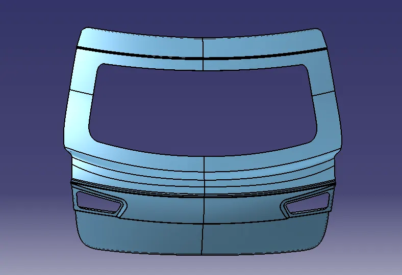
To begin with the given surface should be checked to figure out issues like sharp edges, discontinuity and roughness. backdoor outer upper and lower class a surface has to be repaired according to the smoothness. After repairing the surfaces, the door is divided into two parts as Door Outer Upper and Doo Lower Panel.
| OUTER PANEL |
It is an asthetic surface of backdoor and style surfaces are created based on concept. All other parts or components are created according this surface by considering design criteria. The outer styling skin surface of the back door provided with multistage coatings which has property of scratch resistance, rust prevention etc. It is wrapped around the inner panel through hemming process.
Glass for rear visibility is mounted on the outter panel upper.rear light are also mounted on the outter panel upper.Number plate is mounted on the outter panel lower.Spot welds and other manufacturing process should done only on the inner panel because the outter panel is styling surface which should not have any scratches or welds.Because it affects the style of the car which leads to bad impression on the customer.
 |
TOOLING DIRECTION
- Before starting to design the inner panel of the back door the tooling direction for Deep Drawing purpose should be created.
- Then the styling surface needs to be checked and analyzed since it might have irregularities, hence it must be fixed first.
- Then the back door was designed using the top down approach.
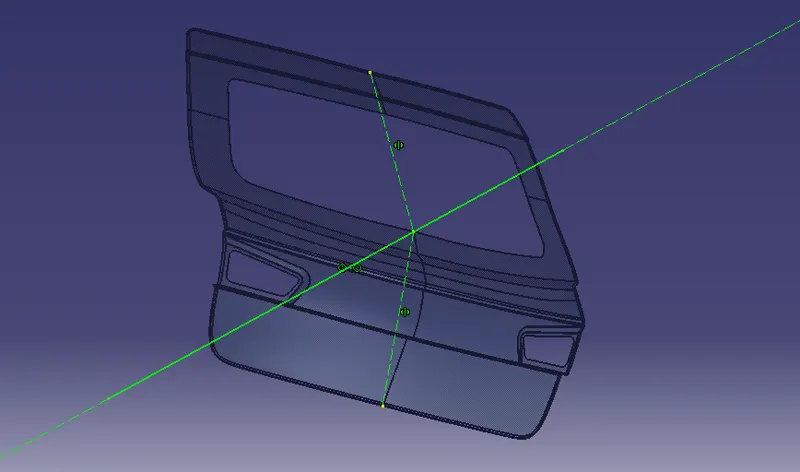 |
Mostly aluminum part is casted, steel inner panel are manufactured by deep drawing process. If deep drawn, there must be a tooling direction through which that panel must be deep drawn.
| INNER PANEL |
The inner panel is one of the most important components of backdoor assembly. It provides strength and helps in dissipation of forces outside the part with the help of embosses made on it. It helps in mounting of accessories like hinges, wiper motor, gas stay, latch & striker etc.
The inner panel is produced by either casting or through Deep drawing process.
Car backdoor inner panel is made of either steel or aluminium.Most of the luxuary car's inner panel are made of aluminium because of its properties.But the cost of aluminium is high.Cost of aluminium is more as compared to steel.To easily understand,the cost of aluminium for inner panel is higher than the cost of all parts of backdoor together.
SEALING FLANGE,
This Sealing flange is that section of the inner panel which enables the backdoor to sit over the rear body side of the car. It is the most important part of the inner panel as it decides how a backdoor is mounted on the rear body side of the car and also restricts any external matter to enter inside the vehicle.
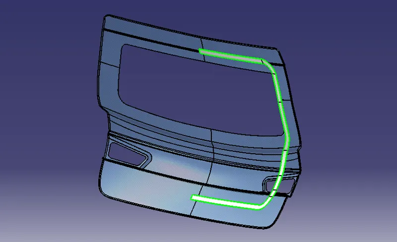 |
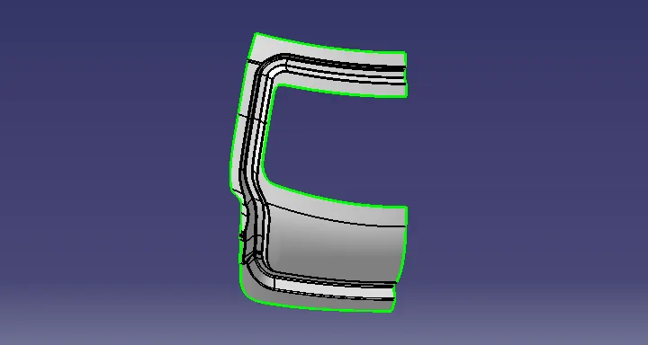
Then we will be creating the Back door inner panel flange by offsetting the outer surface at a distance considering the sheet thickness and thickening direction.
Then created the connecting flange to join the inner panel and sealing flange.
Then for the windshield panel mounting, windshield panel is created and joined with sealing flange.
 |
 |
EMBOSS
It is provided to give extra strength to sheet metal panel locally and to help dissipate forces/energy towards a specific direction. Here embosses (Y/V emboss) are designed in such a way so as to direct them towards the outer end of the backdoor as shown in the image. .Another purpose of giving emboss is to distribute impact forces towards hinges
Requirements:
1. Seat Surface: The starting surface of the emboss.
2. Base Surface: The surface on which embossing should be done.
Manufacturing considerations for the emboss creation
- The distance between the outer edges of the emboss should be a minimum of 5mm.
- Draft angle should be provided to the emboss with 7 deg - 9 deg for the easy removal of the part from the die.
- No sharp corners to be provided in the emboss which would lead to inefficient manufacturing.
- The height of the emboss should not be more than 5mm.
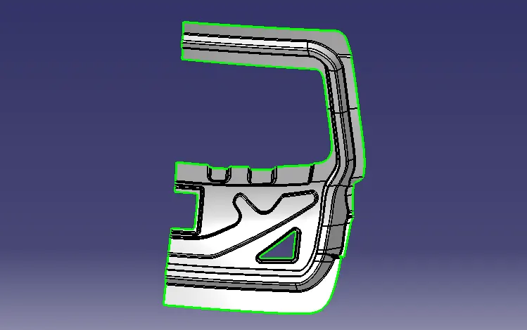 |
Embosses and material are removed on less curve section made on the inner panel for better stiffness and strength. Here there is a huge removal of material which reduces the weight of backdoor. Force directions are specified how the force will be diverted towards the sides of the backdoor hence by safeguards the rear occupants and luggage
Hinge mountings
 |
Gas stay mounting
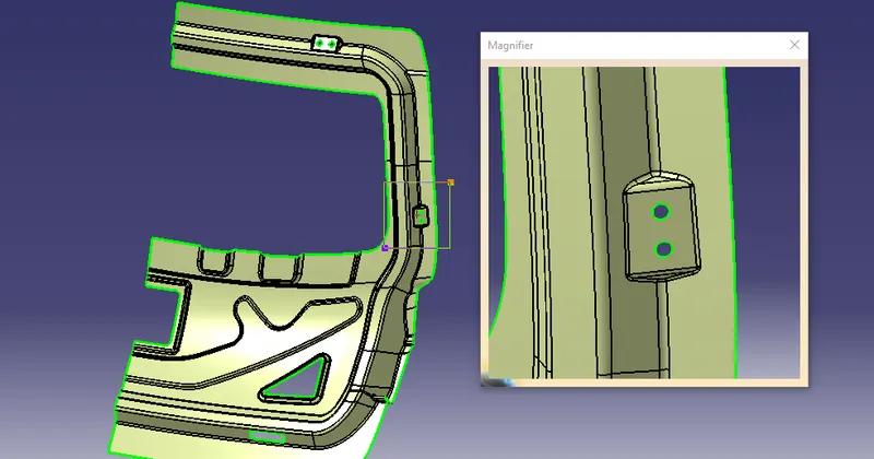 |
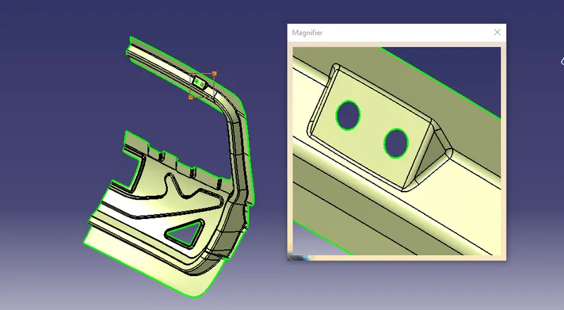
At hinge emboss, hinges will be affixed to this section so as backdoor can swing up and down about the hinge axis.
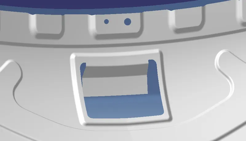
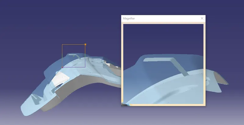
MASTIC SEALANTS
Sealants are used to close the gap between two or more substrates. It also acts as a leakproof between the components. It forms a barrier through the physical properties of the sealant itself and by adhesion to the substrate.
Mastic Sealants are used to join one surface to another or protect the area to which it is applied. It has heat-resistant properties and the ability to form a strong bond which is applied using a mastic sealant gun.
Mastic Sealants have an influence area of 80mm diameter.
 |
 |
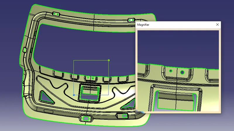
Wiper motor mounting
 |
LATCH AND STRIKER
TRAJECTORY,
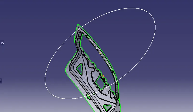 |
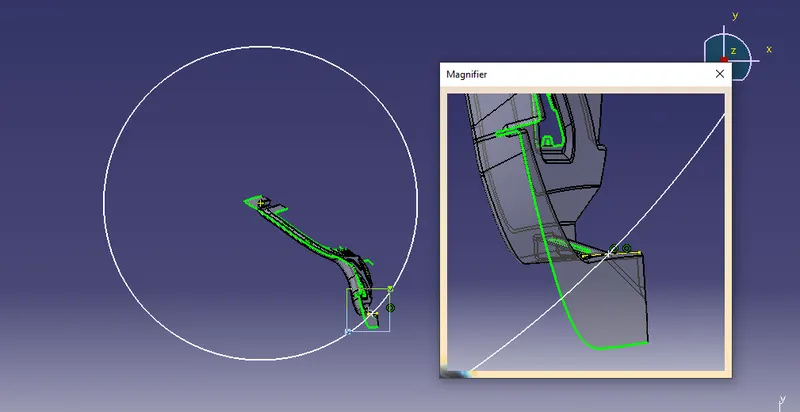
Backdoor is a swinging part so it rotates about hinge axis so the position and orientation of latch-striker are perpendicular to the hinge axis as shown below.
 |
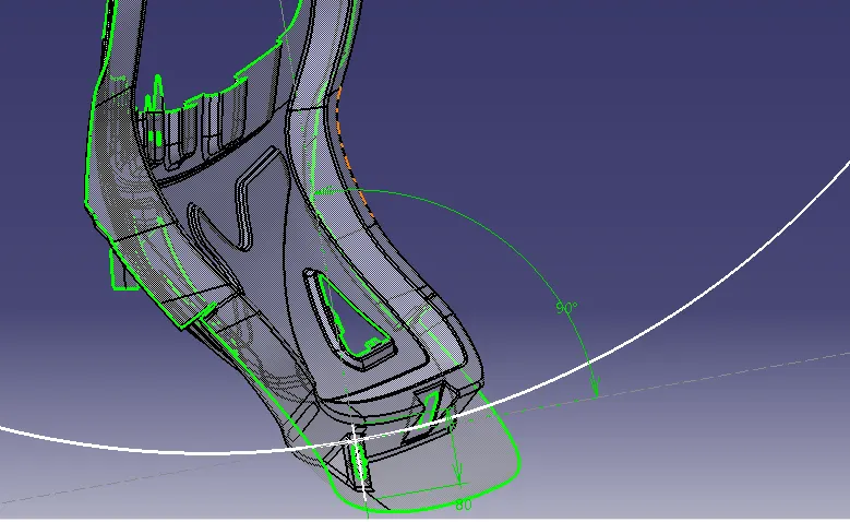 |
As per the desiign consideration the latch and striker mount must be perpendicular to the trajectory. The perdicularity achived by drawing a line tangent to circle (trajectory) with this we can get perpendicular line.
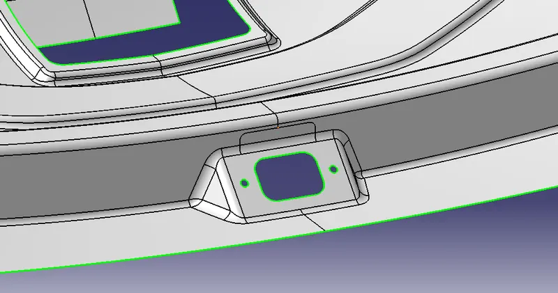 |
All necessary mountings are created as per the design consideration for assembly all the mating surface should be flat to avoid improper fitment. NVH value should be minimized.
INNER PANEL SOLID:
The inner panel is produced by either casting or through deep drawn method.mostly aluminium panel is only casted,steel inner panel is made by deep drawn process only .If it is deep drawn,then there must be a tooling direction through which that direction the panel is Deep Drawn.
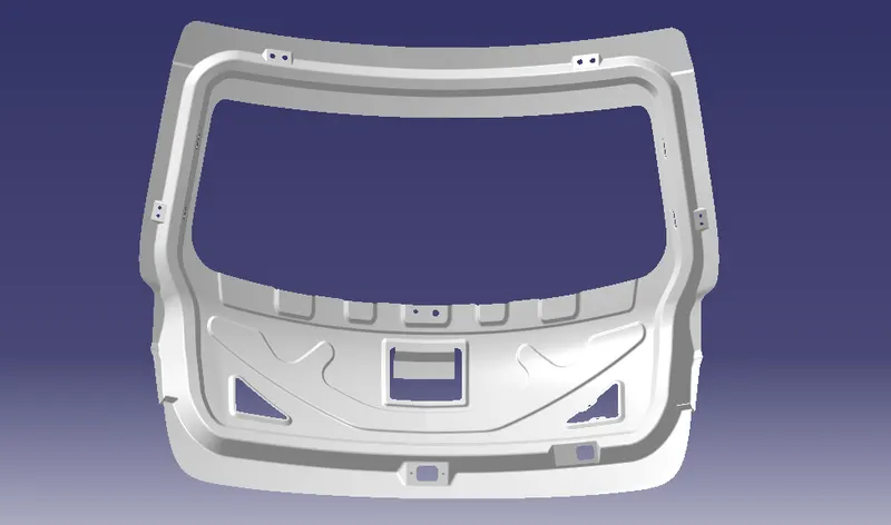 |
- In the above inner panel design, it is made sure that the commodity has good strength and stiffness that's why embosses and material removal is more at flat regions as these regions strength is less. So by embossing and removing material gives better stiffness to the body locally and this also reduces the weight of the commodity.
- The inner emboss structure is also designed in such a way that force should get diverted outside the car body.
- Necessary drain holes are also provided at some sections to give a passage for the liquid to drain out.
- The position of Latch-striker is perpendicular to the hinge axis for perfect locking to rear body side.
- The inner panel thickness is 0.75mm.
- 3 mm is the minimum radius at each bend.
- A vertical rectangular hole is provided on latch-striker location to mount latch-striker.
| REINFORCEMENTS |
Required thickness = 1.5mm
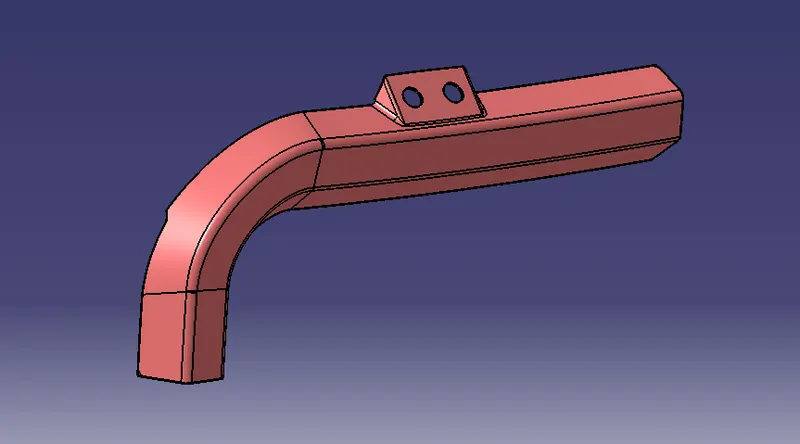
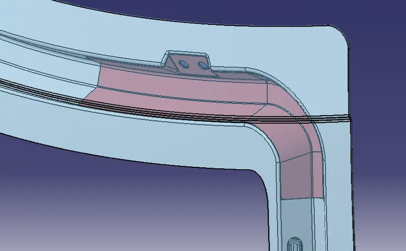
HINGE REINFORCEMENTS:
Hinges support the weight of the whole backdoor.Hence,the reinforcement must be provided there too.The emboss is designed in such a way that the hinge should operate freely.The hinge is connected to the rear roof of the car.
 |
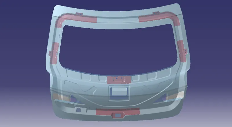
 |
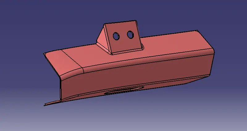
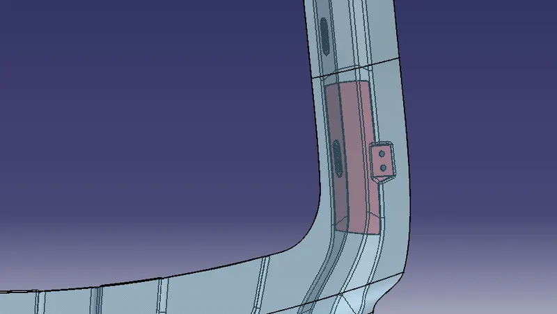
GAS STAY REINFORCEMENT:
Gas stay reinforcement is used to lift the backdoor automatically.There are two types of gas stay one is semi-automated type the back door needs little force to lift after that it lift the backdoor automatically.In fully automated,it has power spindle which lift the bck door automatically.
 |
 |
WIPER MOTOR REINFORCEMENT:
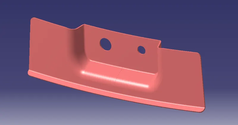
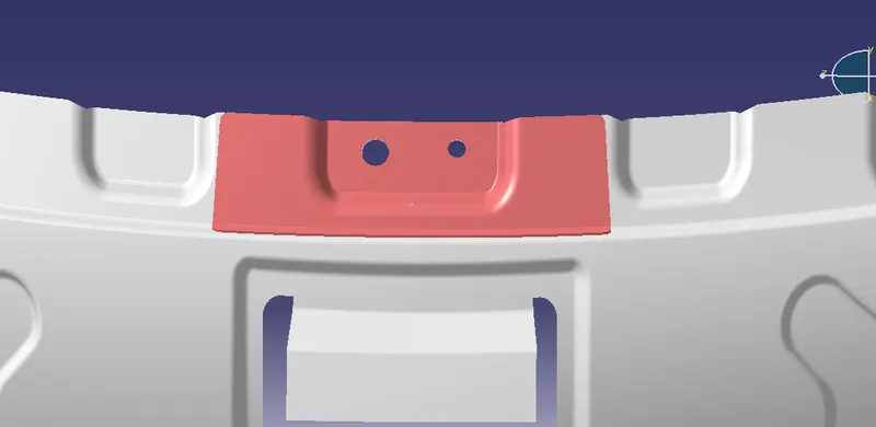
Wiper is ued to to wipeout the rain water falls on the backdoor window.Its actuated by the motor which is mounted on the inner panel.Due to the vibration and heat created by the motor.The inner panel where the motor is mounted gets deform and parts attached to the motor starts to vibrate which leads to poor NVH.So we have to provide the reinforcement where the wiper motor is placed.
 |
 |
LATCH REINFORCEMENT:
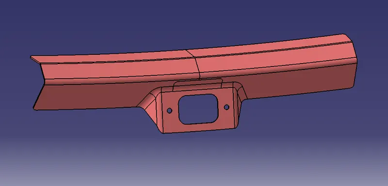
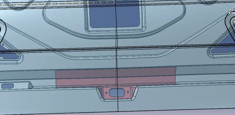
At bottom of the panel,reinforcement and emboss are given to accomodate the latch and striker assembly.Generally key operated or automatic remotly controllable mechanism is used to keep the door open or closed.The actuators,recivers and other electronics devices are mounted on the inner panel only.
 |
 |
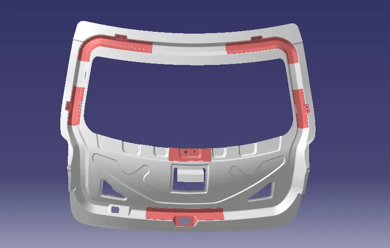
REINFORCEMENTS POSITIONS:
 |
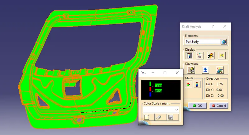
DRAFT ANALYSIS:
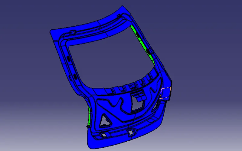
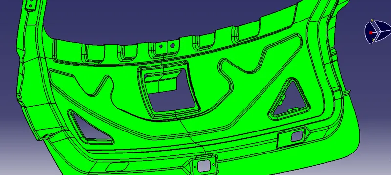
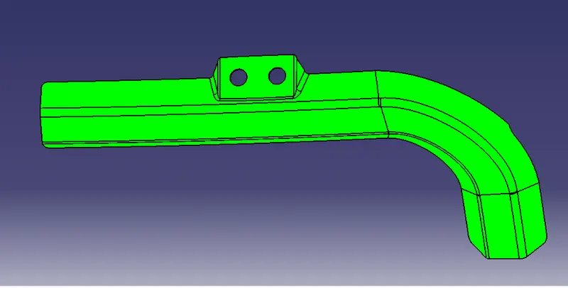
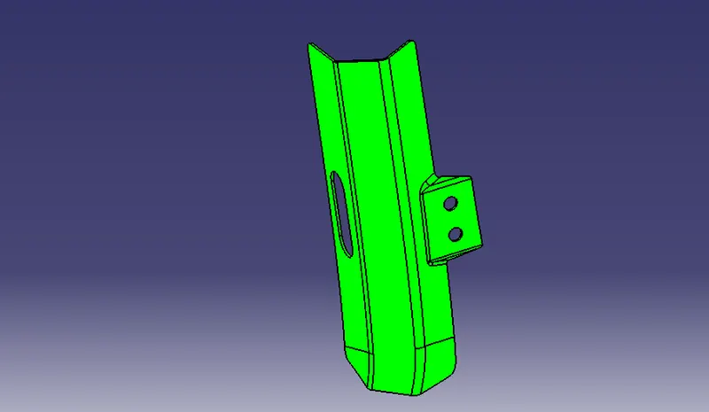
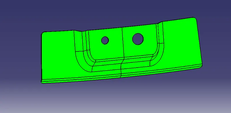
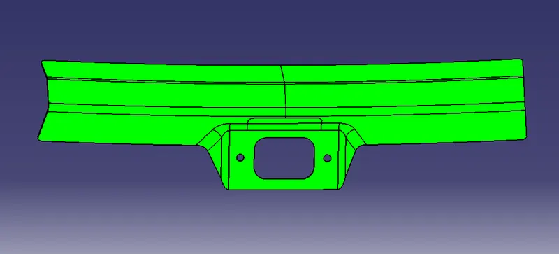
Every part which is manufactured from press tool or other forming tools require some positive draft on the faces which are parallel to the tooling direction. If we don’t give draft (Zero Draft) or give negative drafts on these faces it will stick to the mould surface and when the mould is in motion it will destroy surface thus reducing its surface finish. Thus Draft Analysis command enables us to detect if the part we have drafted can be easily ejected or not. It also give insights about the critical zones, so that appropriate changes in the design can be made if needed.
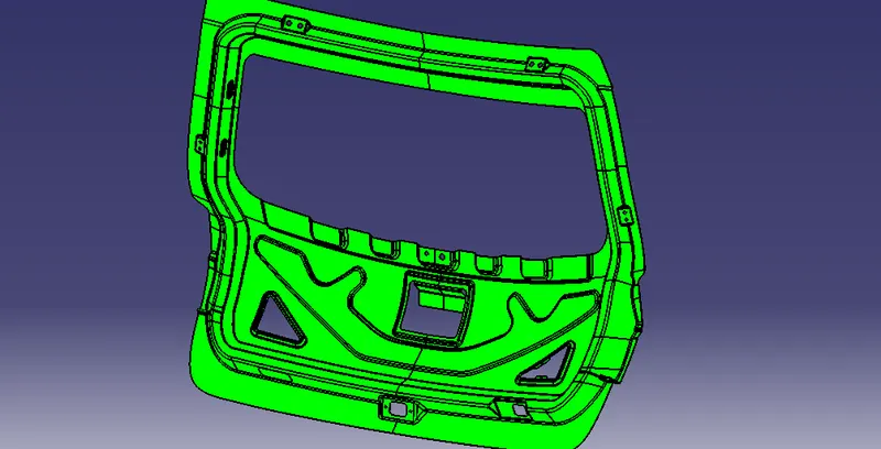
Draft analysis of inner panel is carried out through the tooling direction only. Only the green areas are accepteble and in worst case yellow region are accepteble but the blue and red region are never accepted.
The draft angle for alluminium casted panel is 2 to 3 degree is enough but if its steel then the angle is more than 7 degree.
In this project i considered it as steel and used 7 degree as draft angle and direction is choosen as tooling direction which is the deep drawn direction.
- One of the main reasons for providing draft is to maximise the durabiliity of tools.
FOR INNERPANEL:
 |
 |
 |
 |
FOR REINFORCEMENTS:
 |
 |
 |
 |
| ASSEMBLY OF BACK DOOR |
In this assembly Top down approach was followed wherein from given styling surface the inner panel was created using various tools/commands in CATIA. After that others parts were modelled as per the requirements one by one
HEMMING:
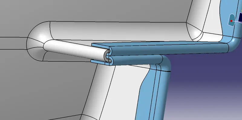
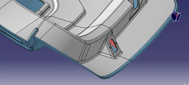
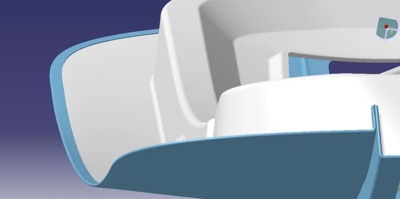
The main reason why we are using hemming for joing the outer and the inner panel is to prevent from asthetic damage or defect. Two parts can be joined by using spot welding bu it leads to affect our required stlye of the surface.
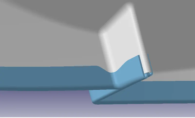
Hemming is a forming operation in which the edges of the sheet are folded over another part in order to achieve a tight fit. Usually hemming operations are used to connect parts together, to improve the appearance of a part and to reinforce part edges. In car part production, hemming is used in assembly as a secondary operation after deep drawing, trimming and flanging operations to join two sheet metal parts (outer and inner) together. Typical parts for this type of assembly are hoods, doors, trunk lids and fenders.
Minimum length should be 8mm to 9mm and 0.2 between two components to apply hemming glues to stuck.
 |
 |
 |
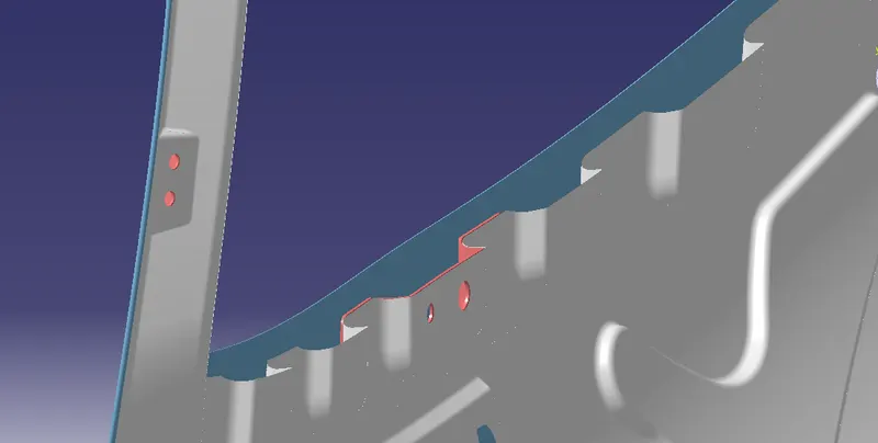
CORNER RELIEF:
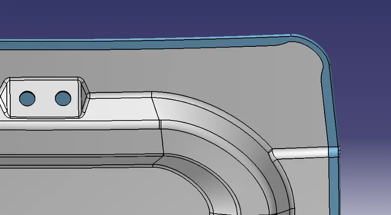
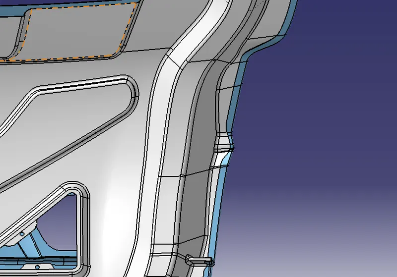
During hemming process multiple rollers are used which causes vibrations and stress concentrations at some locations due to which design intent of the panel shouldn’t be changed (i.e the panel should spring back to original formation after roller is removed). But most of the time that is not the case at corners so to avoid that situtaion reliefs are provided at corners.
 |
 |
 |
Corner relief has to be provided for sheet metal bending. In this case, before the hemming process to control the deformation of the sheet metal and to avoid any tear of the sheet metal during bending.
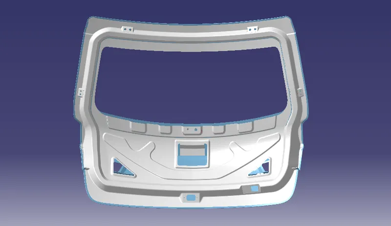
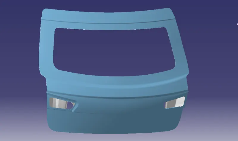
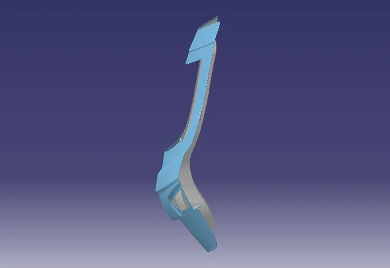
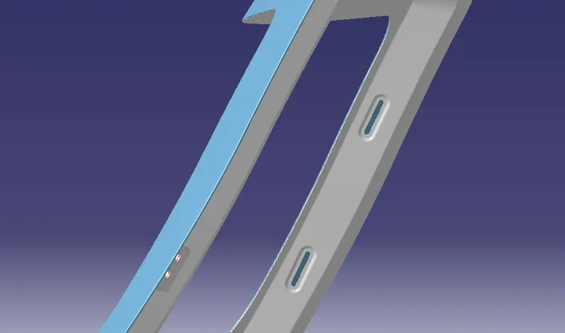
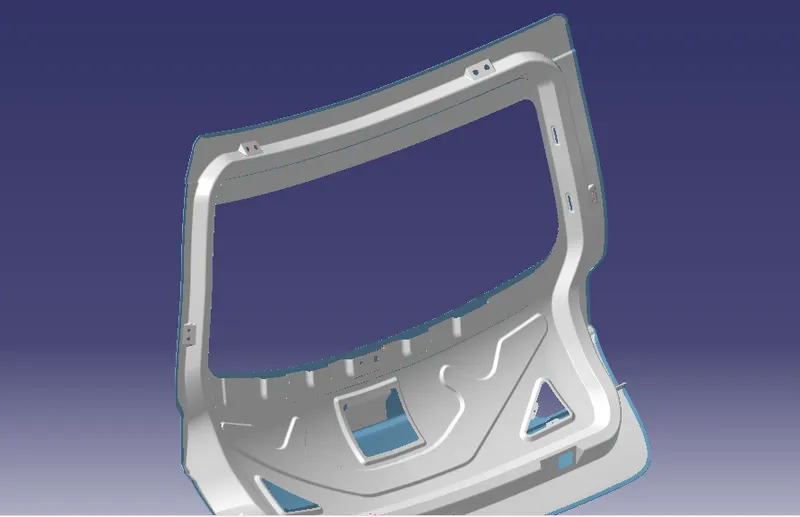
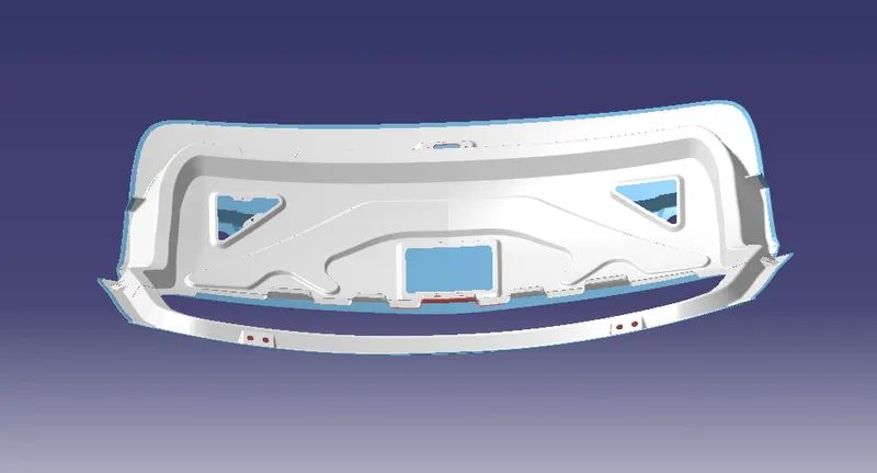
RESULTS,
 |
 |
 |
 |
 |
 |
 |
 |
 |
 |
CONCLUSION,
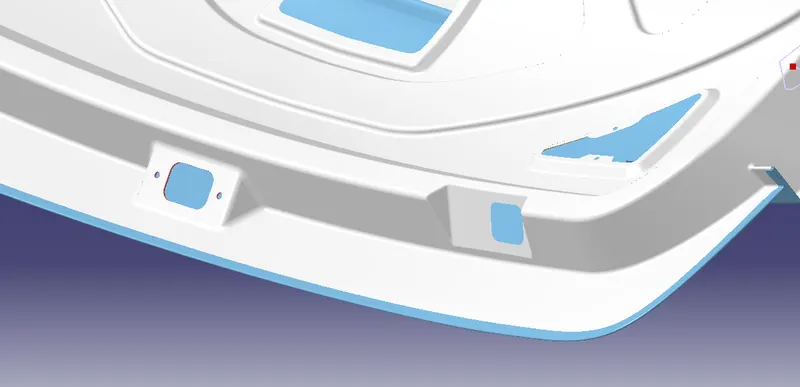
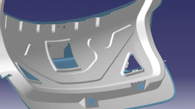
The back door assembly is designed by following the engineering standards from the given styling surface.
- Sealing Flange of length minimum 25mm is maintained throughout.
- Thickness for the reinforcement is 1.5mm.
- Emboss are drawn with respect to the tooling axis so that they clear the minimum draft angle.
- Corner relief is given to prevent unwanted deformation of the sheet metal at the corners while hemming.
- Draft analysis was performed on the inner panel and All the reinforcements were designed and placed at appropriate positions.