Design of backdoor
AIM: To create an ASSEMBLY of Backdoor by the using the provided styling surface to come up with a back door design by using appropriate design methodologies, and providing the necessary reinforcements and embosses.
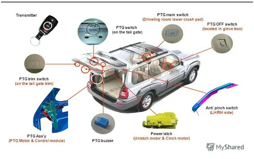
Components in a trunk
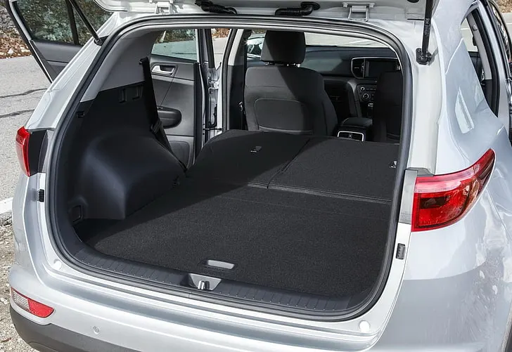
Space in trunk/backdoor
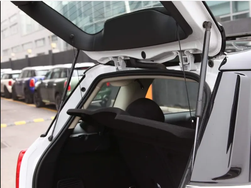
Side view of Backdoor/trunk
OBJECTIVES: To design the backdoor of a car by designing it's upper, lower and inner panel and hinge, gas, wiper, striker reinforcement parts in an assembly. Also mention all the Design Considerations required in mind to design all the parts. Further perform the Draft Analysis of all parts to check for the manufacturing feasibility.
INTRODUCTION:
What is a car backdoor?
In car terminology, a "backdoor" typically refers to the rear door or access panel to the cargo area, often referred to as a "hatch" or "liftgate". The Back door is typically hinged, but sometimes attached by other mechanisms such as tracks, in front of an opening which is used for entering and exiting a vehicle.
The trunk (North American English) or boot (British English) of a car is the vehicle's main storage or cargo compartment, often a hatch at the rear of the vehicle. It is also called a tailgate. These doors can be operated manually or electric powered. In most of the luxury cars door is electrically operated. Ii involves a very major role during rear crash cases. so our design must be obey crash requirements. the institute of highway safety and analyze the different accidents and they set a test to rate our car. so these rating depends upon the design of the trunk and material used, flanges, embosses, type of joining of inner panel and outer panel etc.
Types of backdoors:
1) Top Mounted backdoor:
This type of back doors is used in a station wagon, pickup truck and some of the sport utility vehicles. Today’s modern cars use top-mounted tailgating systems which are both powered and also gas stay supported. These top mounted tailgates provide greater rear visibility compared to side-mounted or bar doors which have canter pillars in it.
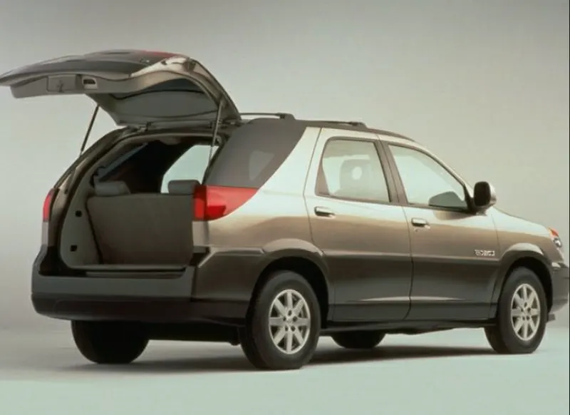
2) Side mounted backdoor:
As the name signifies side-mounted doors are the one which is used in the van type MPVs, SUVs, pickup truck vehicles. These side-mounted doors or barn doors are a lot easier compared to top-mounted doors. These doors are generally smaller in size and can be easily accessed.
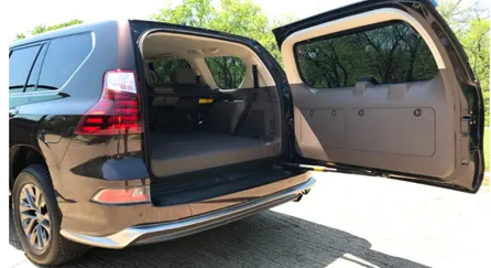
3) Bottom backdoor:
It refers to a tailgate, which is a rear door or opening hinged at the bottom and opens downward. It's a common design for trucks and some other vehicle types, particularly those with cargo areas like pickup trucks, SUVs, and vans.
Backdoor Assembly:
The following components are designed and assembled to form a car backdoor:
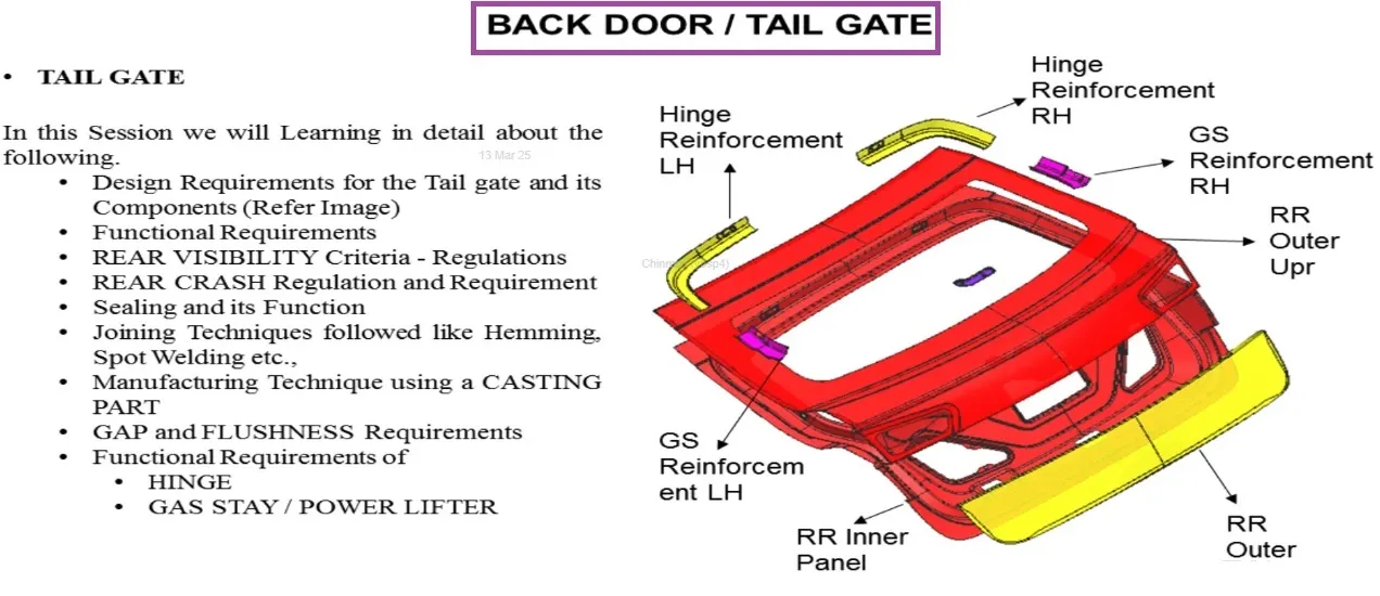
Parts description
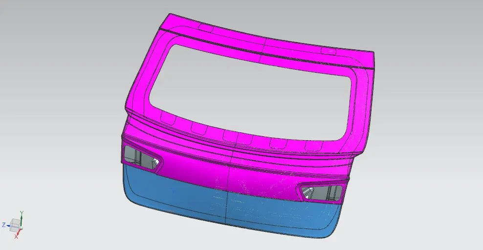
Backdoor assembly
1) Backdoor Upper Panel:
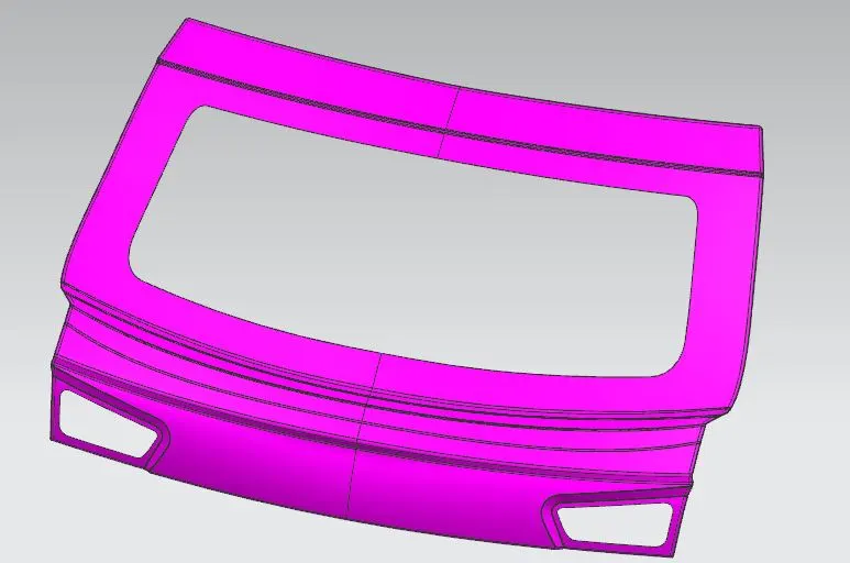
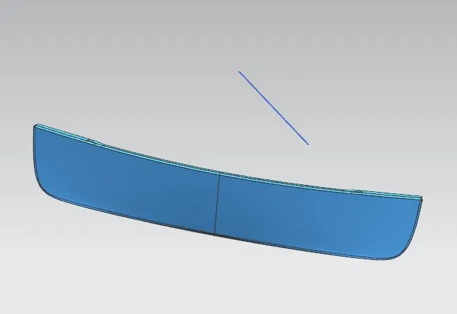
2) Backdoor Outer Lower Panel:
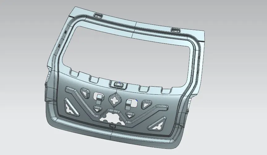
3) Backdoor Inner Panel:
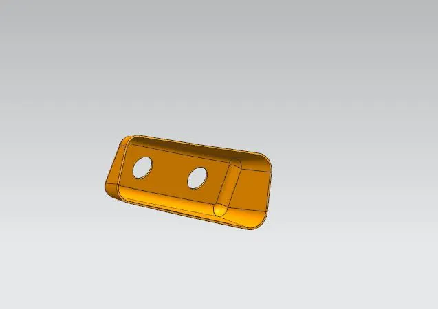
4) Hinge Reinforcement:
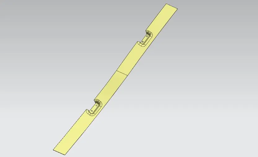
5) Gas Stay Reinforcement:
6) Wiper Motor Reinforcement:
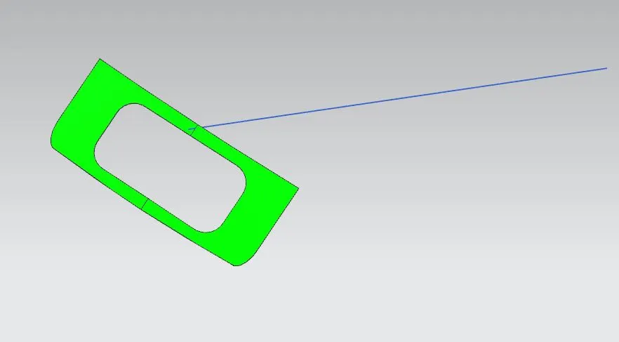
7) Striker Reinforcement:
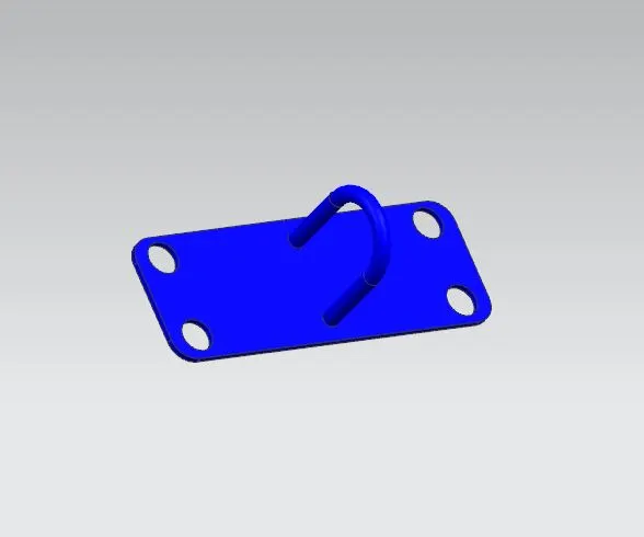
BACKDOOR DESIGN CONSIDERATIONS:
1) Visibility Criteria:
Maintaining rear sufficient visibility for the driver is crucial, especially with smaller hatchbacks cars.
2) Striker Position:
The latch and striker need to be positioned correctly for it's secure closure and smooth or easy operations. The position of striker is sketched with a circular sketch perpendicular to the inner panel for close and accurate positioning.
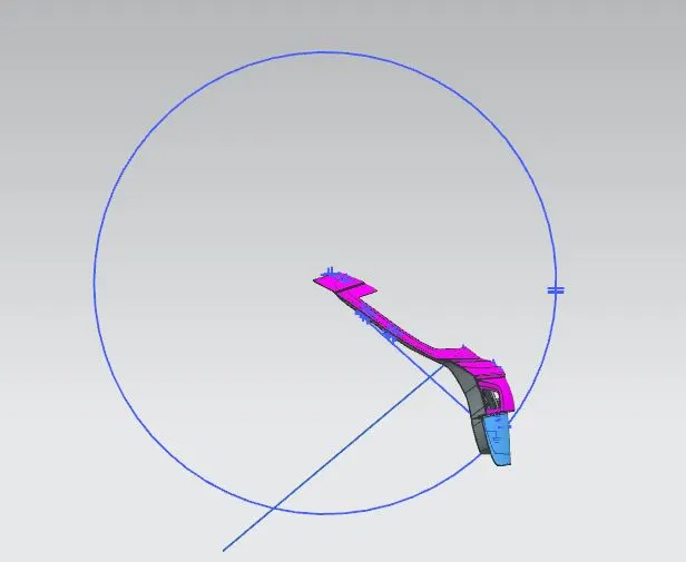
Circular sketch for correct positioning
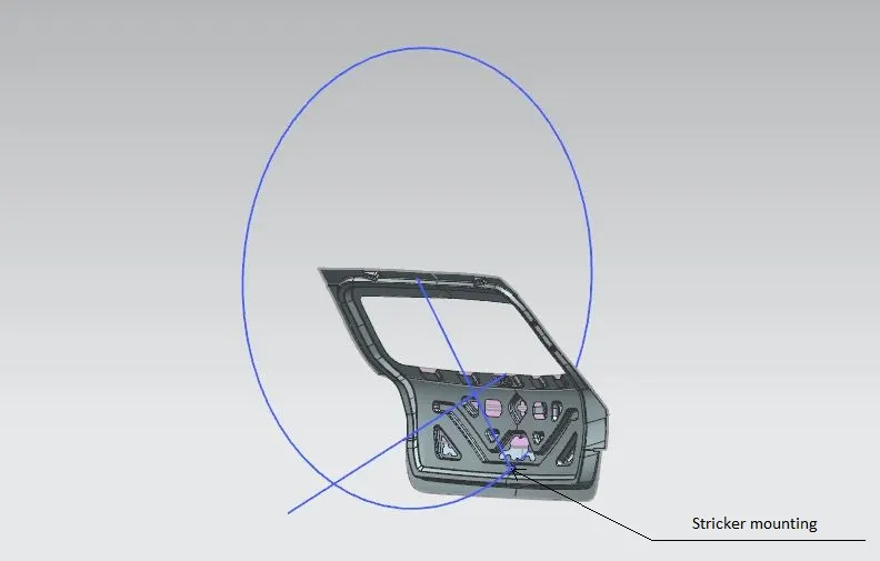
Position of striker mounting on the basis of sketch
3) Hinge Position:
The hinge need to be positioned correctly for it's secure closure and smooth operations. Hinges need to be robust and provide smooth opening and closing of the door. The position of hinge should be above the inner panel so that the hinge can support the assembly and can be opened and closed with ease.
4) Gas Stay Position:
The gas stays assist in holding the door open. It usually provide a support between inner and outer panel and support for the locking of backdoor.
5) Space Availability:
Space availability is determined by the maximum Luggage volume a car can have. This is the design needs to maximize cargo space while still ensuring a functional and aesthetically pleasing the backdoor.
6) Manufacturing techniques:
Different Sheetmetal processes used for manufacturing the backdoor. The individual parts are manufactured using following techniques:
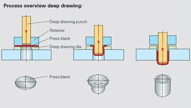
Deep Drawing: The metal deep drawing process is an effective method of manufacturing of cups, cans and other similar deep drawing products. The deep drawings having two main categories:
1) Stage drawing: The blank shape of metal is placed on the die and contact with the punch. When the metal specimen is flat piece of sheet metal used in forming and finish the product. Initially the punch moves in downward direction. The outer rim of blank is subjected to pure radial drawing (drawing toward in vertical axes) between die and blank metal. The metal become a bend and sliding over die and also stretched between die and punch. The metal in vicinity of punch head and contact with it bend and slide over radii and stretch over punch head.
2) Redrawing: The components drawn from first stage again it's redrawn to transform into more depth to form a cup shape in the die and punch. The second stage of drawing is called as redrawing.
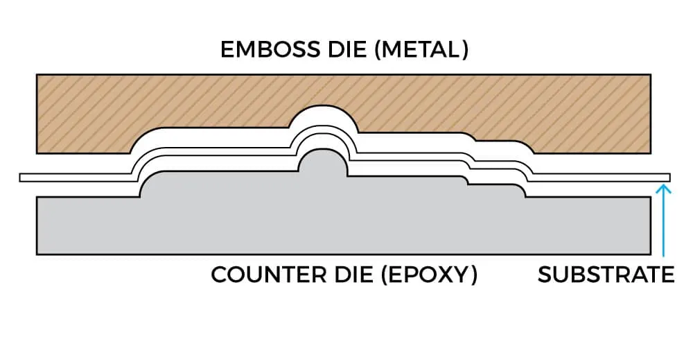
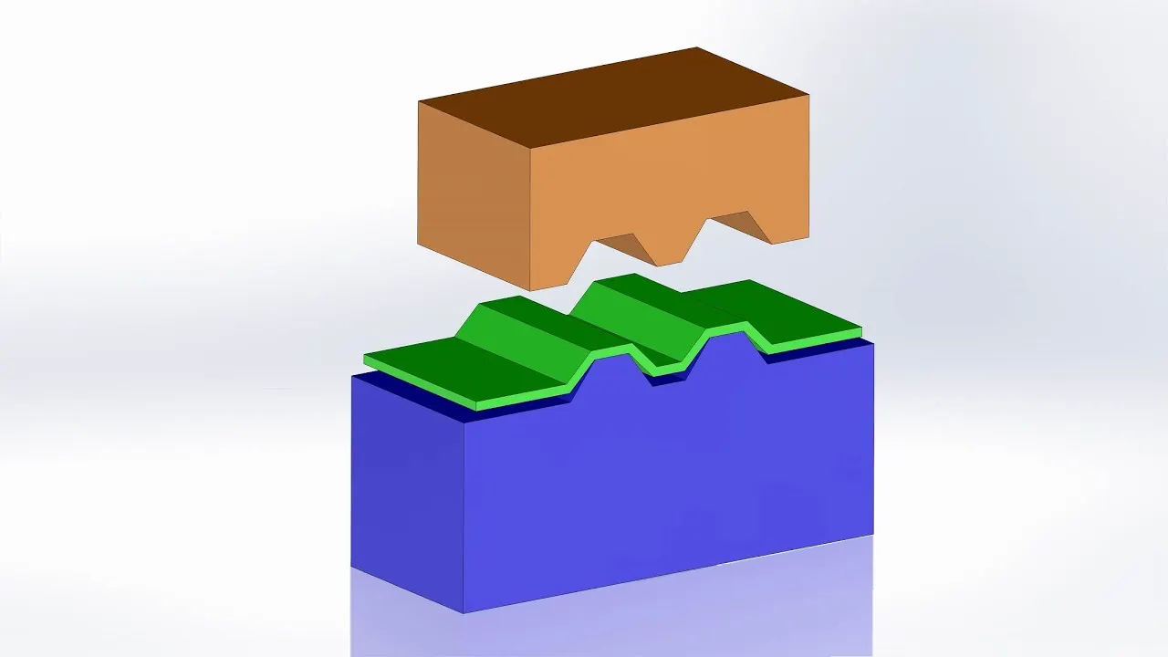
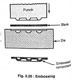
Embossing: Embossing is a metal forming process for producing raised or sunken designs or relief in sheet materials by means of matched male and female roller dies, theoretically with no change in metal thickness or by-passing sheet or a strip of metal between rolls of the desired pattern. Metal sheet is drawn through the male and female roller dies producing a pattern or design on the metal sheet. Depending on the roller dies used, different patterns can be produced on the metal sheet.
Materials commonly used in the metal embossing process include:
1) Aluminum alloys
2) Steel alloys
3) Zinc Copper
4) Galvanized steel
5) Brass
6) Cold rolled steel
7) Joining Techniques:
To join the different parts in the assembly, these following techniques are followed to achieve the required backdoor assembly:
Hemming: Hemming is a forming operation in which the edges of the sheet are folded or folded over another part in order to achieve a tight fit. Normally hemming operations are used to connect parts together, to improve the appearance of a part and to reinforce part edges.
In car part production, hemming is used in assembly as a secondary operation after deep drawing, trimming and flanging operations to join two sheet metal parts (outer and inner) together. Typical parts for this type of assembly are hoods, doors, trunk lids and fenders.
There are various types of hemming operations:
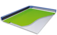
1) Conventional die hemming: In conventional die hemming, the flange is folded over the entire length with a hemming tool.
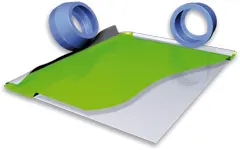
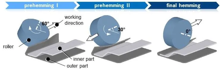
2) Roll hemming: In roll hemming, the hemming roller is guided by an industrial robot to form the flange.
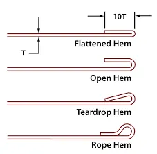
Open Hemming: A Hem has a full round feature and a return flange. In open hem bend angle is equal to 180 degrees.
Tear drop Hemming: In tear drop hem the bend angle is greater than 180 degrees.
Closed Hemming: Hems without any inside radius are called as closed hem. Closed hems are not recommended if the hem geometry is to be painted or if the material used is SST or Aluminum.
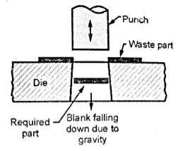
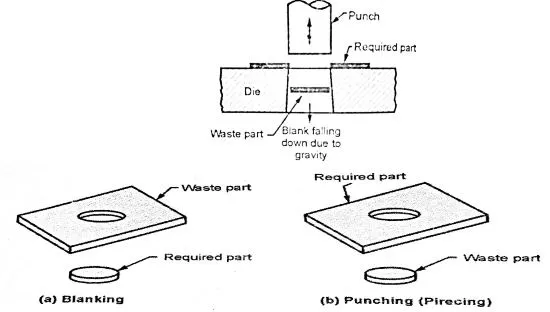
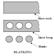
Blanking: Blanking is a cutting operation of a flat metal sheet and the article punched out is known as blank. Blank is the required product of the operation and the metal left behind is considered as a waste.
Punching: It is similar to blanking only the main difference is that, the hole is the required product and the material punched out from the hole is considered as a waste.
8) Manufacturing methods and feasibility:
Backdoor Design feasibility studies assess the practical and economic viability of proposed designs, ensuring solutions are realistic and resource-efficient before implementation. To increase the feasibility of the manufacturing this following design features are considered:
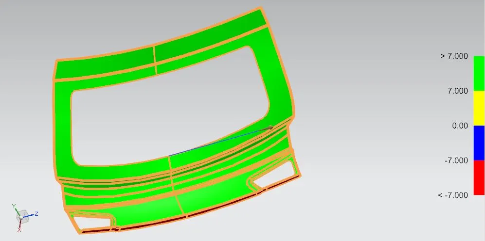
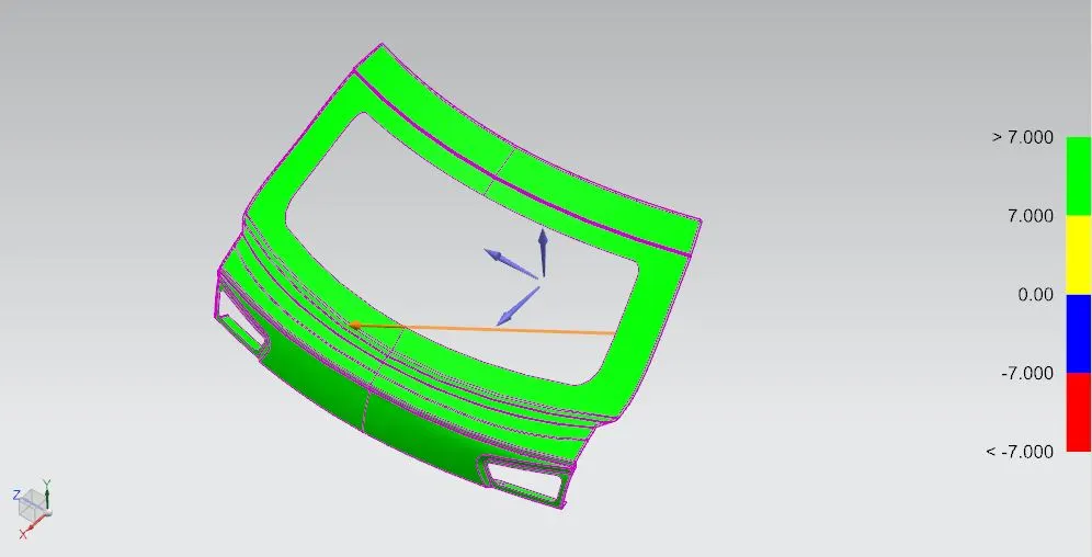
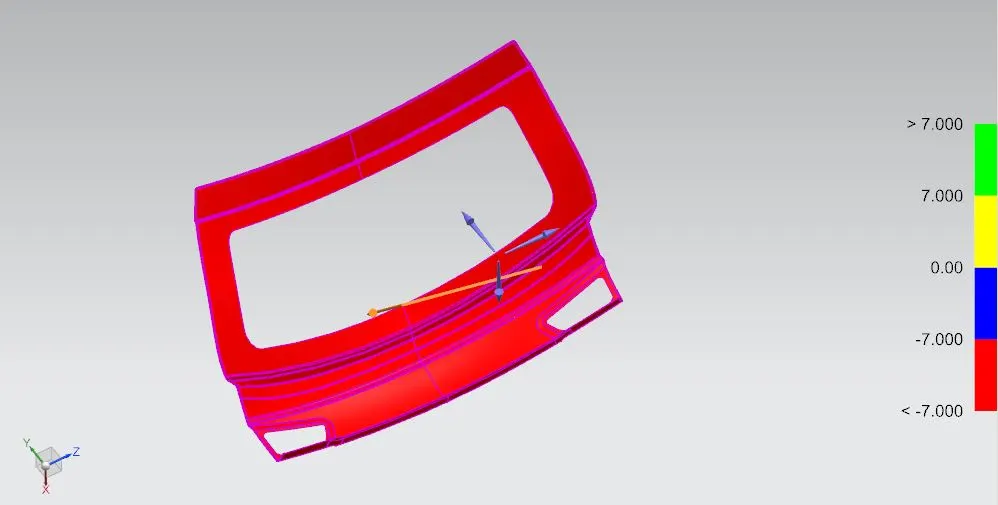
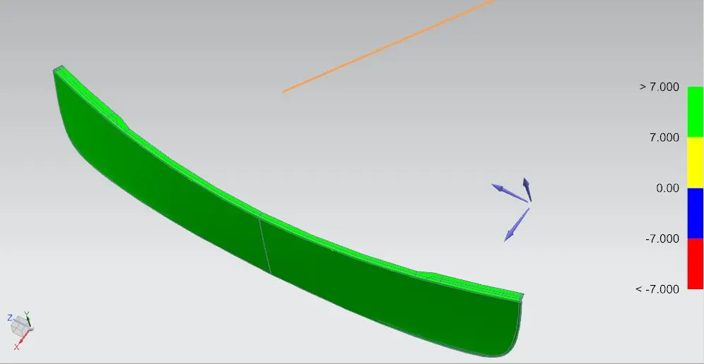
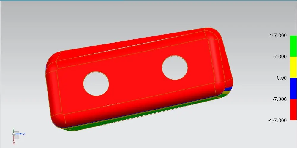
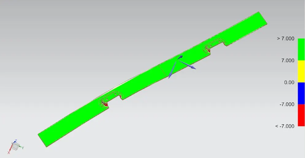
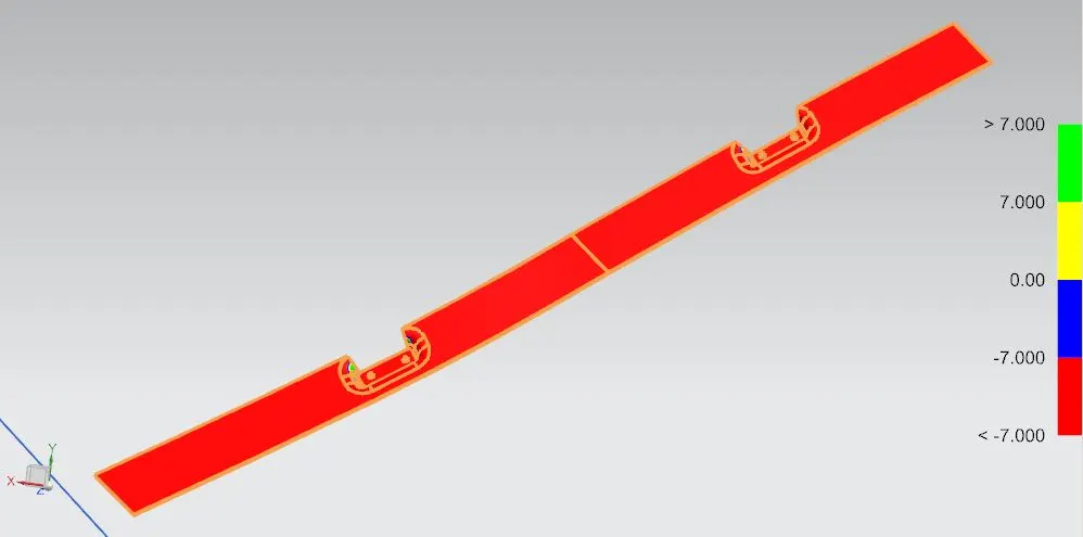
1) Draft Analysis: Draft analysis is used to ensure that the parts drafted will be easily removed. It is performed based on color ranges identifying zones on the analyzed element where the deviation from the draft direction at any point, corresponds to specified values. Minimum draft angle of 7 degree is considered for analysis. Draft Analysis is done separately for following parts for backdoor assembly:
1) Backdoor Upper panel:
a) Surface:
i) Positive side:
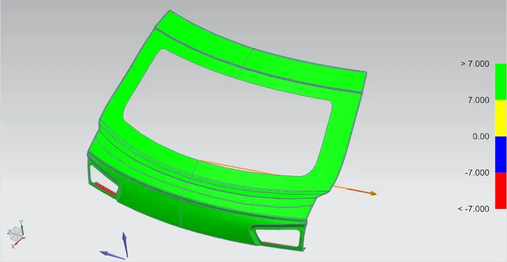
ii) Negative side:
b) Solid part:
i) Positive side:
ii) Negative side:
2) Backdoor Outer Lower panel:
a) Surface:
i) Positive side:
ii) Negative side:
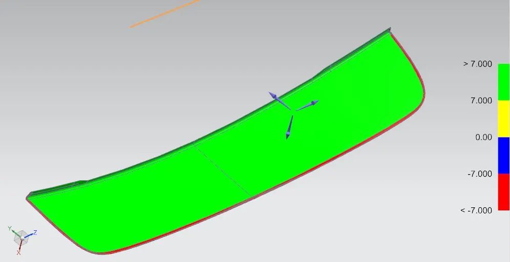
b) Solid part:
i) Positive side:
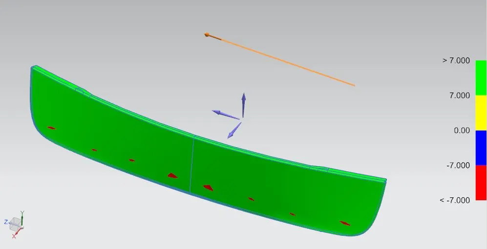
ii) Negative side:
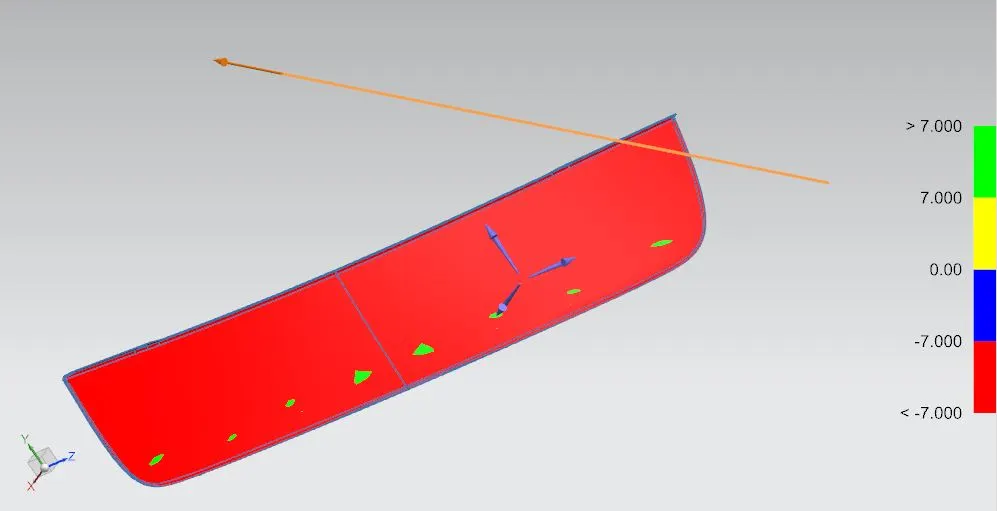
3) Backdoor Inner panel:
a) Surface:
i) Positive side:
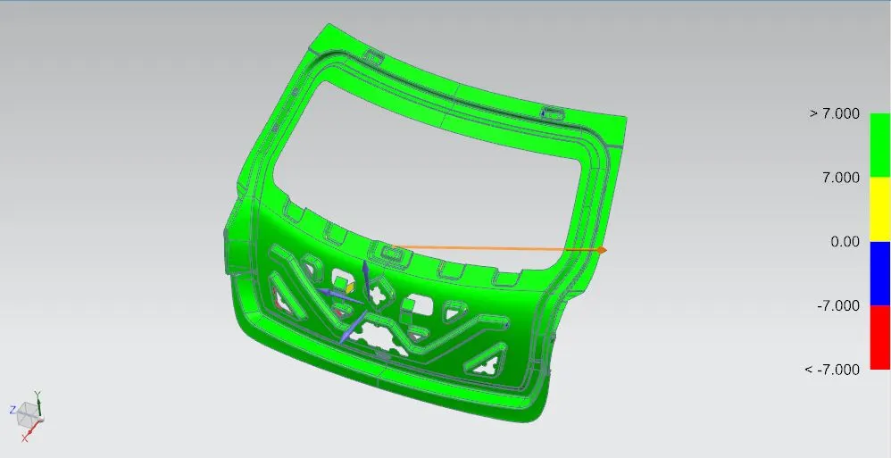
ii) Negative side:
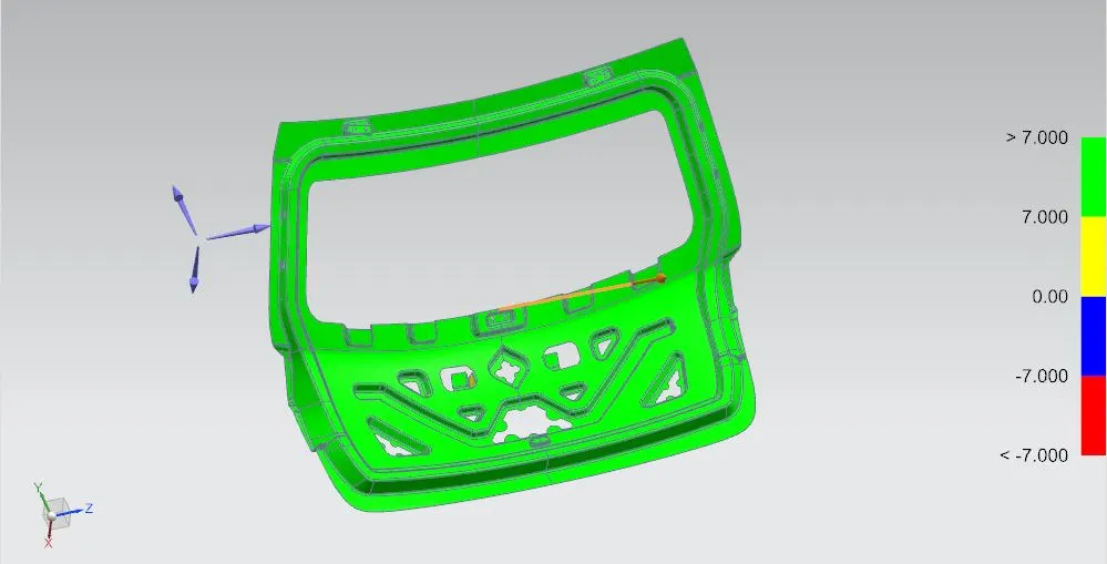
b) Solid part:
i) Positive side:
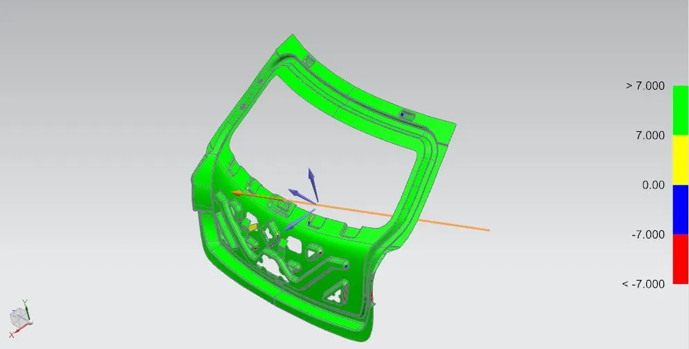
ii) Negative side:
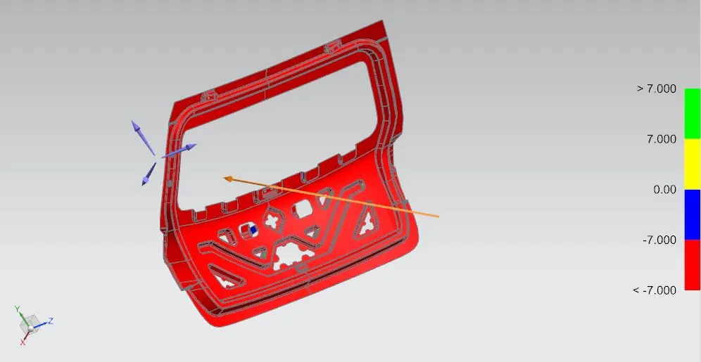
4) Hinge Reinforcement(LHS):
a) Surface:
i) Positive side:
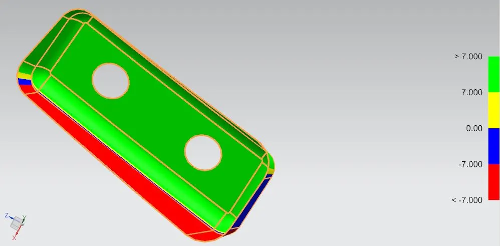
ii) Negative side:
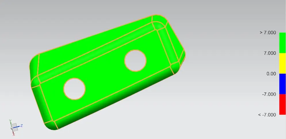
b) Solid part:
i) Positive side:
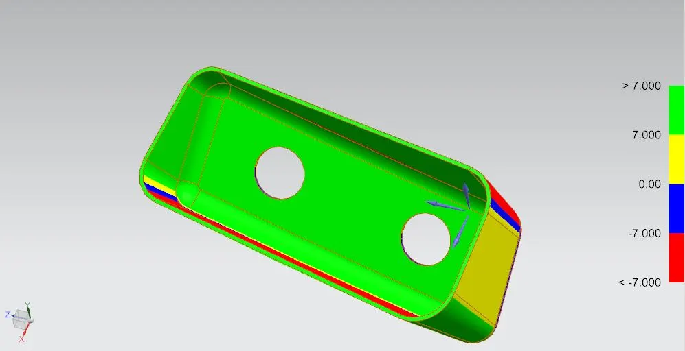
ii) Negative side:
5) Hinge Reinforcement(RHS):
a) Surface:
i) Positive side:
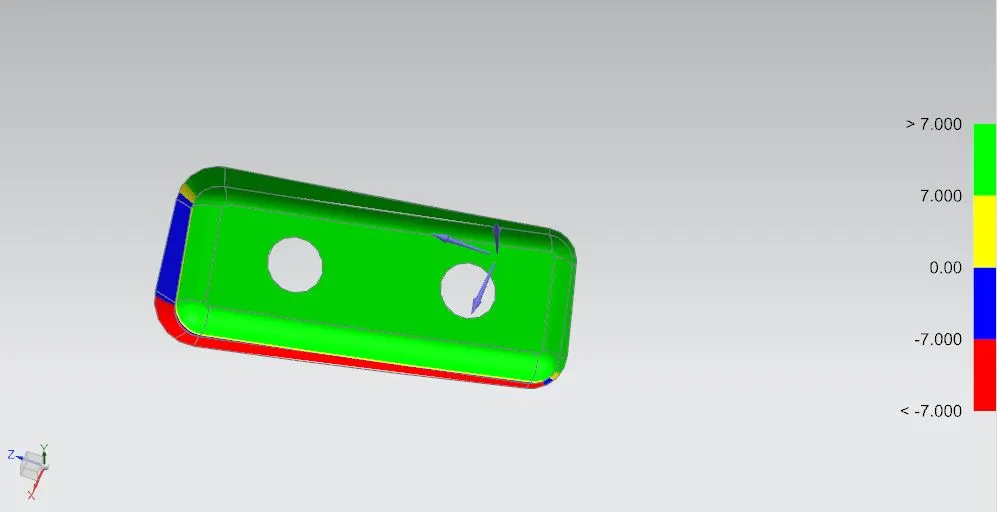
ii) Negative side:
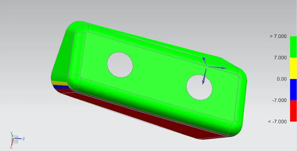
b) Solid part:
i) Positive side:
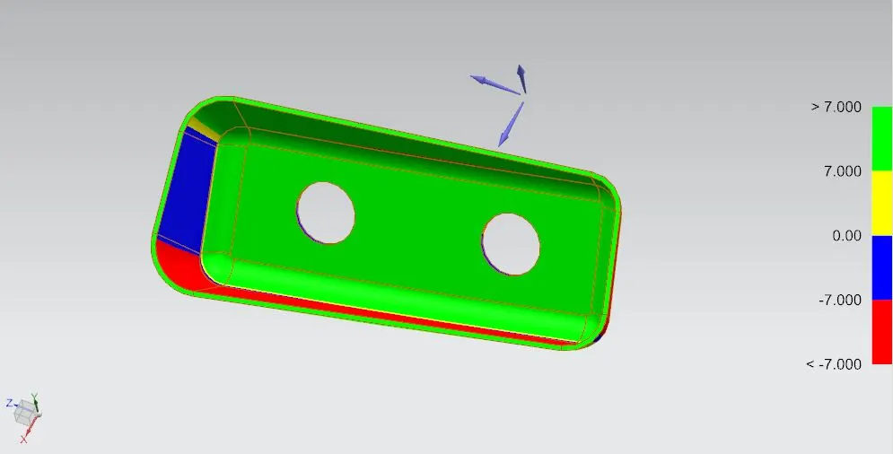
ii) Negative side:
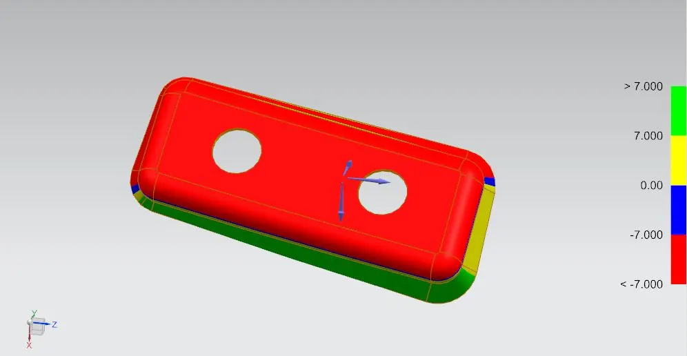
6) Gas Stay Reinforcement(LHS):
a) Surface:
i) Positive side:
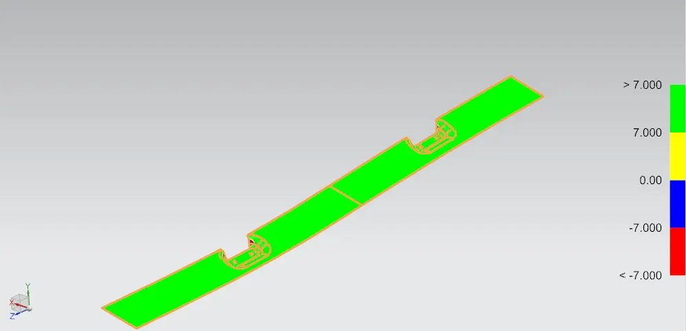
ii) Negative side:
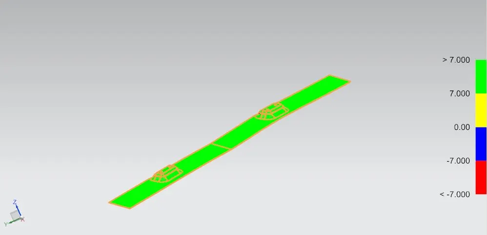
b) Solid part:
i) Positive side:
ii) Negative side:
7) Gas Stay Reinforcement(RHS):
a) Surface:
i) Positive side:
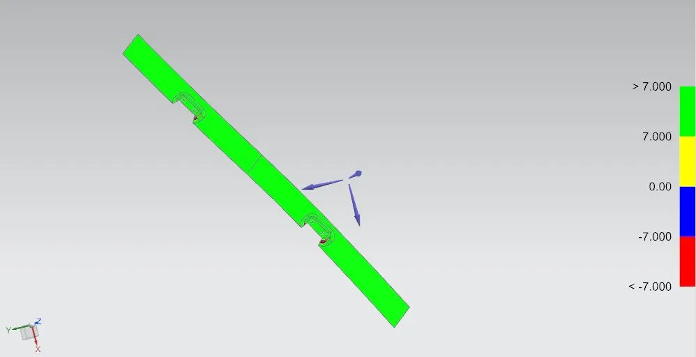
ii) Negative side:
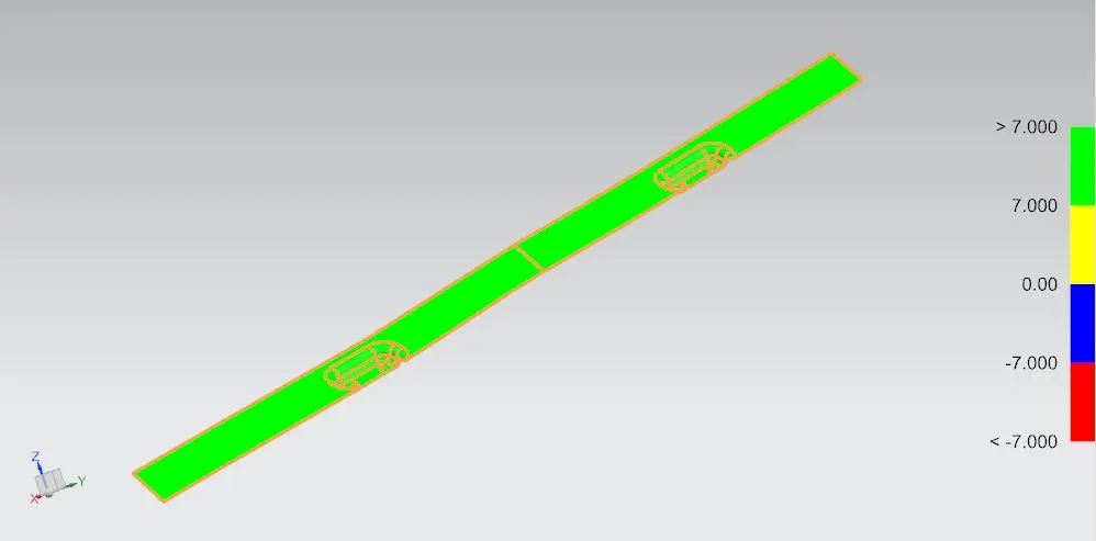
b) Solid part:
i) Positive side:
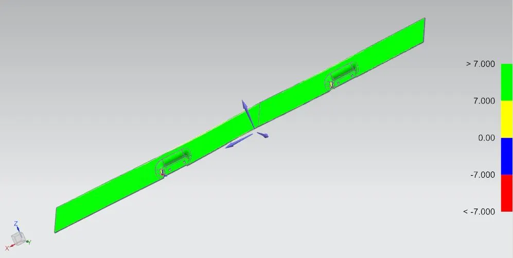
ii) Negative side:
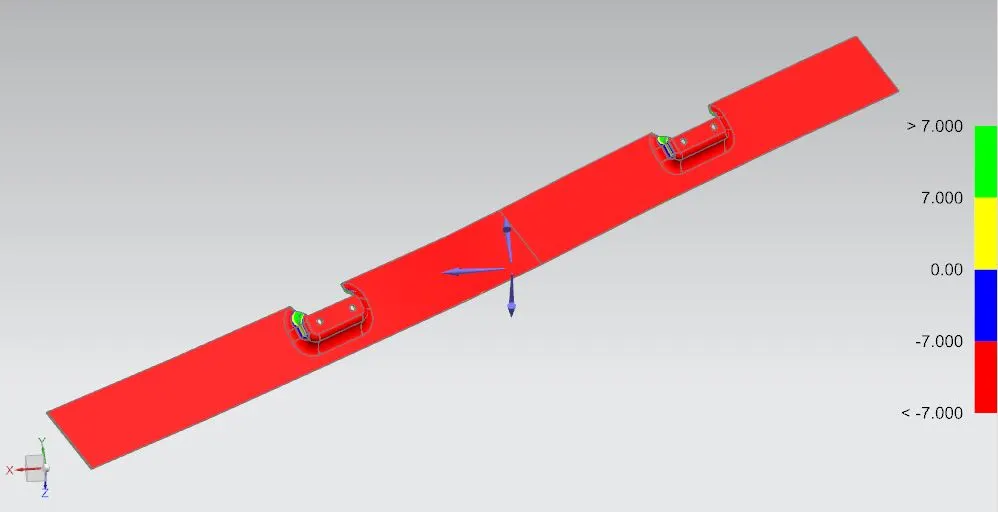
8) Wiper Motor Reinforcement:
a) Surface:
i) Positive side:
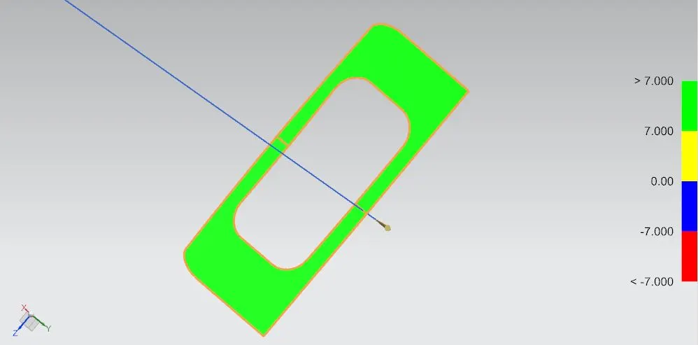
ii) Negative side:
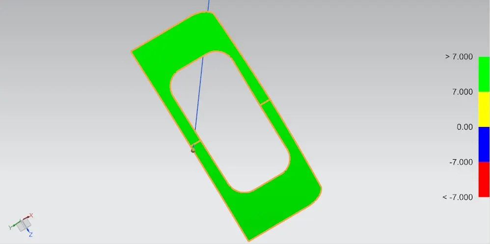
b) Solid part:
i) Positive side:
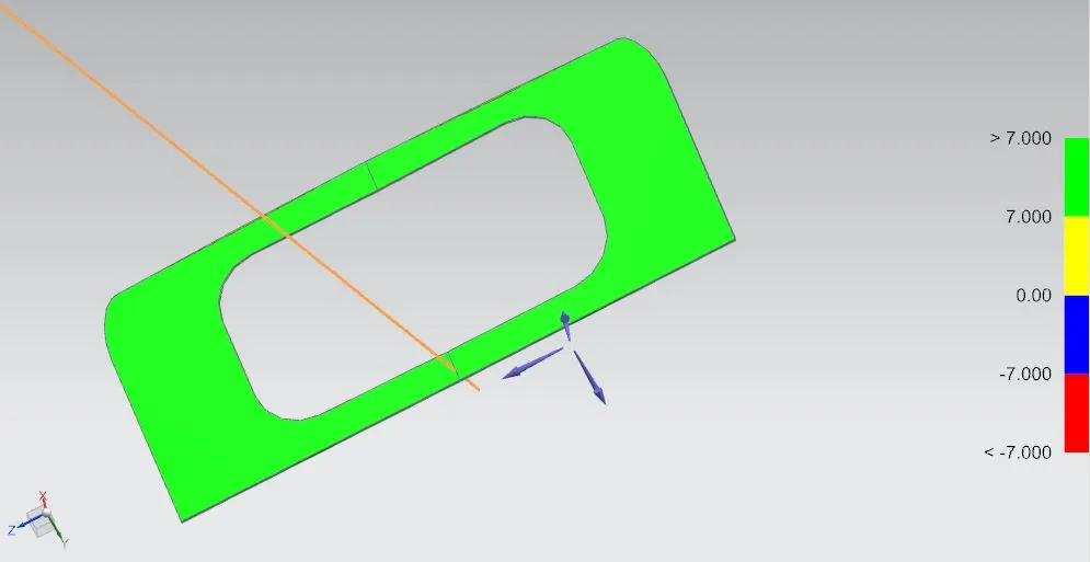
ii) Negative side:
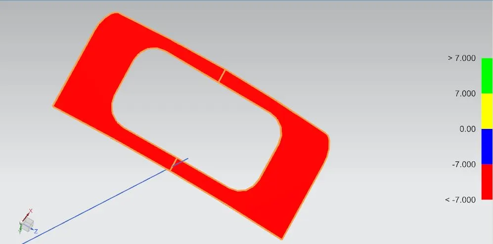
9) Striker Reinforcement:
a) Surface:
i) Positive side:
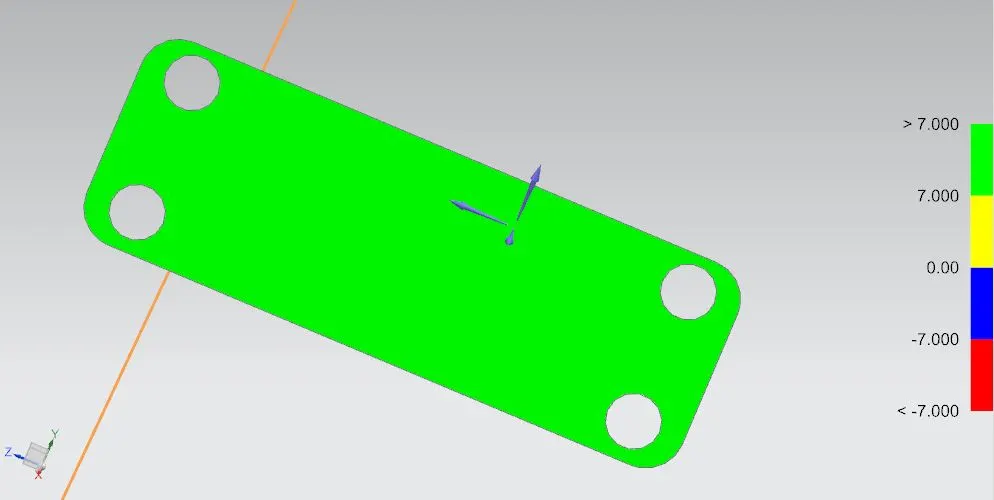
ii) Negative side:
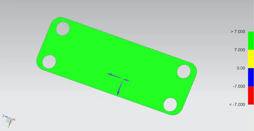
b) Solid part:
i) Positive side:
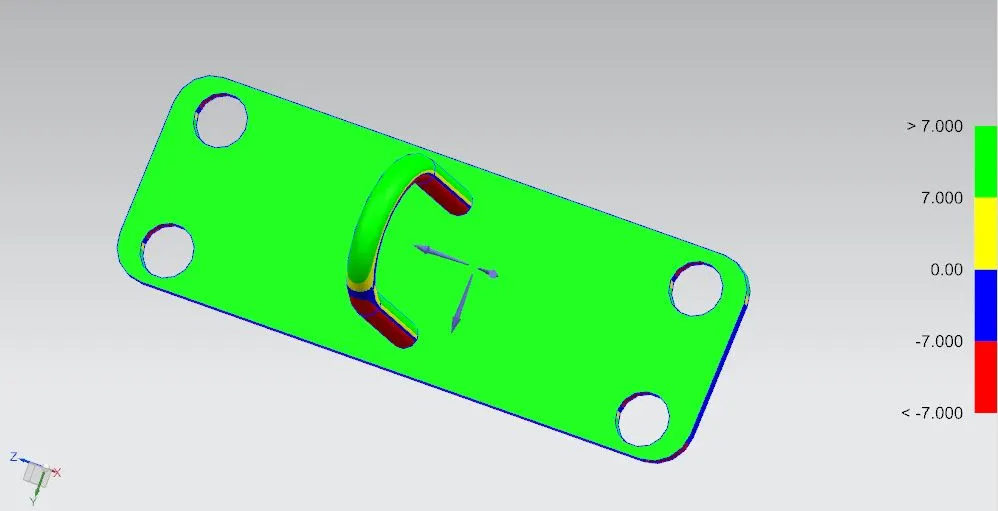
ii) Negative side:
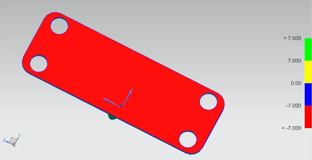
2) Thickness and Spacing:
Thickness of all the parts are taken as t=0.75mm. The spacing between inner and outer panel is 2mm and the clearance for the hemming glue is 0.2mm.
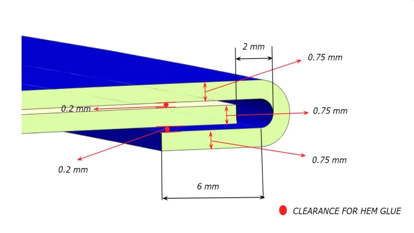
Design considerations of thickness for parts
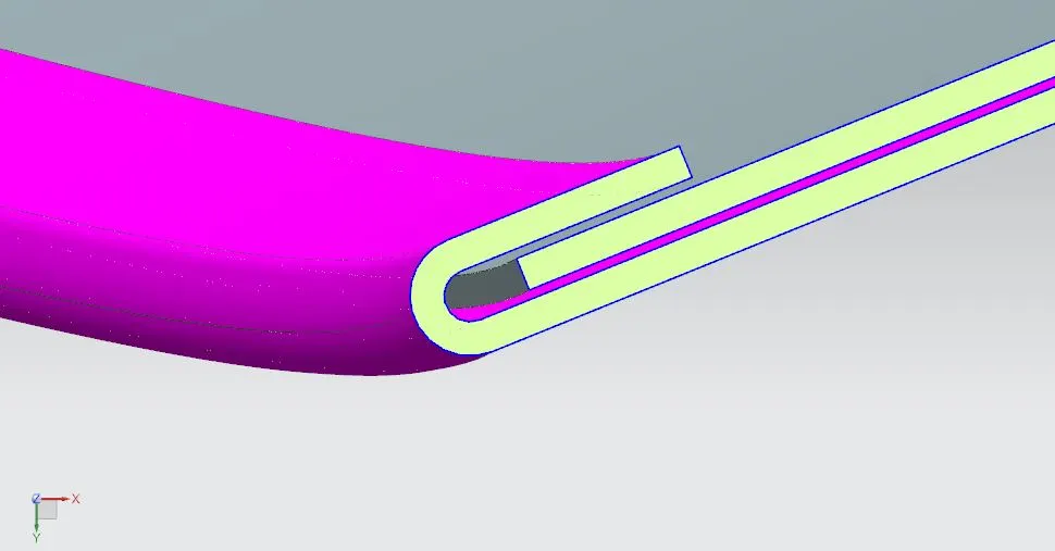
Section view of assembly to show thickness of hemmed parts
INFERENCE:
The backdoor has been successfully designed considering all the design Rules, Master sections, Manufacturing feasibility, Draft analysis, Heat distortion criteria, and snow load analysis. Design was successfully completed using SIEMENS NXCAD as per the given master sections. The position of bow roof rails are as per the given standards with Draft analysis & section analysis to ensure the manufacturability and feasibility of every components.
The assembly and its parts are are saved in a folder. That folder is saved in a Google Drive and after that it's link is pasted in a Word file and the Word file is saved in a .zip file given below.
Google Drive Link: https://drive.google.com/drive/folders/1gufCs7-5ff7pLBWxCHBdFslgE-6GmCar?usp=drive_link