Design of backdoor
Backdoor Design
Aim: To design a sheet metal panel of backdoor from the provided skin data taking all the design rules into consideration.
INTRODUCTION:
A door is a hinged part which is used for entry and exit of the vehicles. Back doors are one of the type doors of the vehicle which are located next to the passenger seat which provides access to the luggage compartment. In most of the cars, these back doors are operated with the help of gas stay which in turn reduces the effort required to lift open the door. Some luxury cars have powered backdoor which in turn is driven by an electric motor. This kind of system is also called a powered trunk lid system. Hatchback or station wagons are sold as 3 door or 5 door models. In this case, the rear hatch is classified as door this is because it enters the passenger compartment. The naming is mainly used in Europe countries. In case of safety, the back door designed should meet the safety requirement for the rear collision.
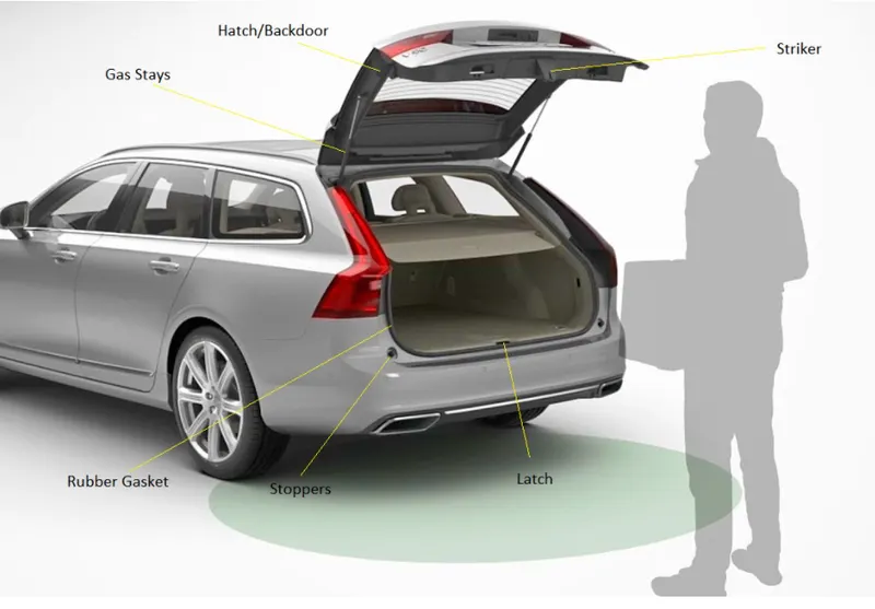
Types of the back door
Top-Mounted :
This type of back doors is used in a station wagon, pickup truck and some of the sport utility vehicles. Today’s modern cars use top-mounted tailgating systems which are both powered and also gas stay supported. These top mounted tailgates provide greater rear visibility compared to side-mounted or bar doors which have canter pillars in it.

Side Mounted Doors :
As the name signifies side-mounted doors are the one which is used in the van type MPVs, SUVs, pickup truck vehicles. These side-mounted doors or barn doors are a lot easier compared to top-mounted doors. These doors are generally smaller in size and can be easily accessed.

Types of mechanisms for Rear Door:
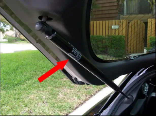
Gas stays:
Gas stay types backdoor/liftgate/tailgate is an ideal and most commonly used tailgate mechanism from lower segment car to luxury car segment. The ideal components of tailgate consist of a hinge, door, gas stay and some rubber beadings for sealing of door.
Powered lift system:
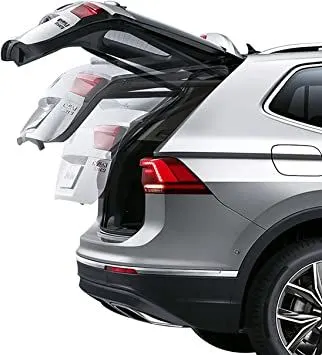
Power trunk lid system is another sophisticated way of trunk/liftgate opening mechanism which is to automatically open and close of the trunk/liftgate and release of the latch by the touch of a button.
Design Methodology:
We start with the styling surface that is provided to us, and consider top-down approach for this assembly modeling. First, we create the assembly and then create the components in the assembly file itself. Inner and outer panel are the largest parts and all other parts depend on them so we start with them. Also, the given styling surface is part of the outer panel so we create it first. Using various commands and features we design the outer panel from the styling surface. We have 2 parts for outer panel, which are separated by a flange, hence we create outer panel upper and lower respectively. They will be spot welded with each other. It is necessary to make sure that all the surfaces are properly joint to their adjacent surface and there are no disjoints at their intersection edges to avoid further errors. Also, Inner and outer panels are connected by hemming process so we can come back to outer panel and do that that after completion of inner panel.
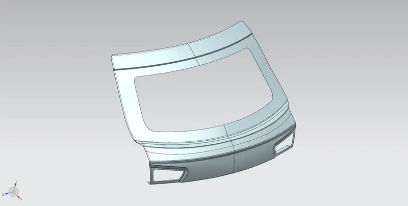
Fig.12 Outer Panel Upper Part
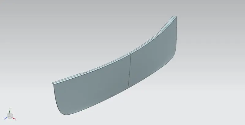
Fig.13 Outer Panel Lower Part
Now, as we know inner panel is at a particular distance from outer panel, we offset the outer panel surface and design inner panel on the same. Inner panel is important as most the mountings will be done on it. Before starting inner panel design, we need to define the tooling direction as a reference for manufacturing team. Then we design the inner panel.
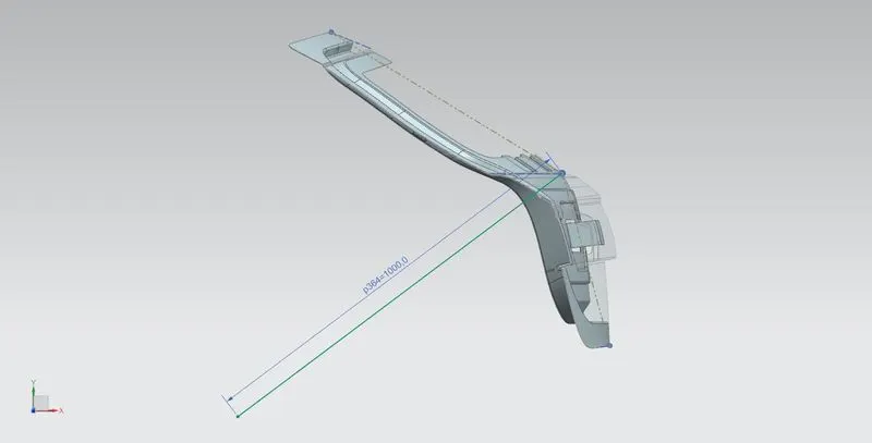
Fig.14 Tooling Direction
While designing the inner panel we need to consider various factors like the mounting point positions, mastic sealant application positions and the cut outs in sheet to make access to tail light assembly easier. As the bottom center part of inner panel is not connected to outer panel, we need to create a surface that comes out and connects to outer panel as shown in the image. This part will be connected to outer panel using mastic sealant. Also, the hinge embosses must be taken by considering proper directions. The emboss surface must be parallel to z-axis to get proper geometry for the latch striker path curve. Then we draw a line connecting the hinges, such that it forms the hinge axis (axis around which the door rotates while opening or closing). Then we can draw a circle with center at the hinge axis and circumference passing somewhere around the emboss endcap. So that when we get the emboss for latch striker mounting, we can take the end cap by creating a plane normal to the path (using On Curve) in the direction normal to the path of striker. Thus, after some trial and error, we can adjust the emboss and the circle dimensions properly.
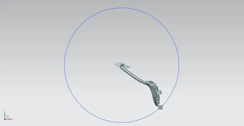
Fig.15 Latch Striker Path
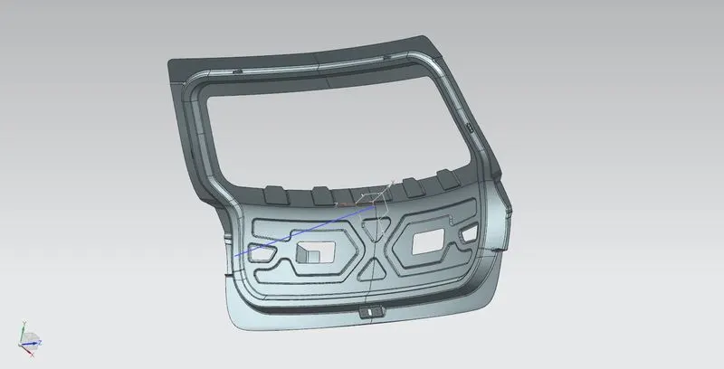
Fig. 16 Inner Panel
As the inner and outer panel are connected by hemming process, we can complete the hemming after completion of inner panel. Now, as major parts are designed, we can move to reinforcements. It is fairly easy to design reinforcements as shown in image below and detailed images above as we can use the inner panel surfaces using Wave Geometry Linker into the corresponding reinforcement parts.
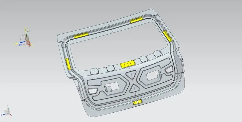
Fig.17 Reinforcements
Important features used while designing:
- Wave Geometry Linker – With this you can create, associative or linked copies of any entity of a part into other parts. It may be a surface, edge, curve, body, sketch etc. The changes made to the original entity will be reflected in the copy of that entity.
- Extract Body – It is used to create an associative body by extracting faces, entire body or region of faces.
- Bridge Curve – It helps to create a tangent blend curve between two objects. The objects may be edges or sketch curves.
- Sew – It combines sheet bodies together by sewing their common edges. There shouldn’t be any gaps larger than specified tolerance.
- Unsew – This command is used to separate the existing sheet body or solid body into multiple bodies.
- Projected Curve – It is used to project an existing curve/curves on a selected plane or surface by selecting a direction for projection.
- Trim Body – It is used to trim one or more bodies using a face or plane. You can also specify the bodies to retain and the bodies to discard.
- Offset Surface – It allows you to offset one or more existing surfaces.
- Offset Curve in Face – This command will allow you to offset particular edges or curves on selected faces.
- Trim Sheet – It is used to trim off a portion of a sheet body using curves, faces, edges or planes.
- Through Curves – It will allow you to create a body Through multiple sections, where it’s shape changes to pass through each section.
- Law Extension – This command extends a curve or edge to create a sheet body at desired angle length by changing the rules under angle law and length law.
- Trim and Extend – It helps you to trim and extend intersecting surfaces and make corner at their intersection.
- Face Blend – It creates fillets between faces.
- Edge Blend – It creates fillets on edges.
- Extend Sheet – It will allow you to extend an existing surface to required distance.
- Emboss – Emboss command creates an embossing by modifying a body with faces created by projecting a curve/section along a direction. You can modify the emboss using options like endcap location and draft angle.
- Mirror Geometry – As name suggests, it allows you to mirror geometries about selected plane or surface.
- Thicken – It is used to convert a surface to solid body by providing thickness.
- Extrude – It helps you to create a feature from a sketch. You are also able to create thin feature using a sketch or curve under this command.
In order to make sure the drawing of inner panel body is proper; we do draft analysis. We need to define the drawing direction and select the inner panel body. We take limit angle as 5 degrees. The result of the draft analysis is as follows,
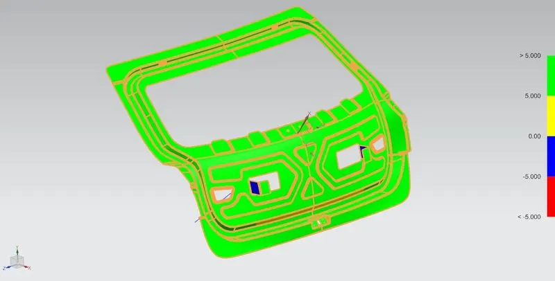
Fig.18 Draft Analysis Result
Portions that require different manufacturing method, or are not in the direction of drawing may not be considered in draft analysis results.
Conclusion: Car back door was designed using the given styling surface, and under provided design regulations.