Design of backdoor
BACK-DOOR DESIGN
Objective:
Utilizing the styling surface provided, design the backdoor inner panel, including reinforcements, and then join the inner and outer panels through use of hemming and mastic seals.
Software Used:
NX CAD Student Version
- INNER PANEL DESIGN:


Figs 1a & 1b – Rear door on hatchback (left) and station wagon (right) (https://en.wikipedia.org/wiki/Hatchback)
A hatchback rear door is a rear automobile door that swings upward to provide access to a cargo area. These types of rear doors are found on hatchbacks, fastbacks, station wagons, and sport utility vehicles (SUVs). As per Wikipedia, “hatchbacks may feature fold-down second row seating, where the interior can be reconfigured to prioritize passenger or cargo volume. Hatchbacks may feature two- or three-box design.”
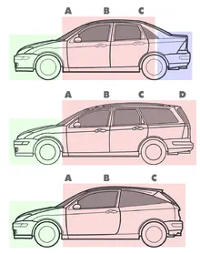
Fig 2a - from top Sedan, Station Wagon, and Hatchback
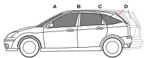
Fig 2b – Compared with a hatchback, the station wagon has a fourth “D” pillar and extended rear section.

Fig 3 – Citroën C3 rear door
In the rear door, gas stays typically hold the door open, and assist with opening and closing. The door is secured shut with a latch and striker.
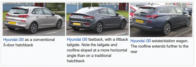
Figs 3a, 3b, 3c
Design of Rear Door
The parts in the rear door assembly consist of:
- Rear door outer panel (upper) – 0.75mm steel sheet
- Rear door outer panel (lower) – 0.75mm steel sheet
- Rear door inner panel – 0.75mm steel sheet
- Hinge reinforcements (left and right) – 1.5mm steel sheet
- Gas stay reinforcements (left and right) – 1.5mm steel sheet
- Striker reinforcement – 1.5mm steel sheet
- Rear wiper motor reinforcement – 1.5mm steel sheet
Design considerations:
1. Safety
- Rear visibility
- Crash worthiness
- Durability
- Weather sealing
- NVH – noise, vibration and hardness
- Cyclability of door opening/closing
- Longevity of gas stays
- Comfort and convenience
- Rear headroom
- Cargo area
INNER PANEL DESIGN:
The inner panel is designed with embosses for strength and cut-outs for weight reduction and management of Center of Gravity. The embosses protrude towards the rear, so that they are the first to absorb and impact. Mastic points are added to the center of the panel, for added strength and rigidity.
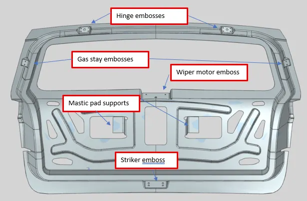
Fig 4a – Front
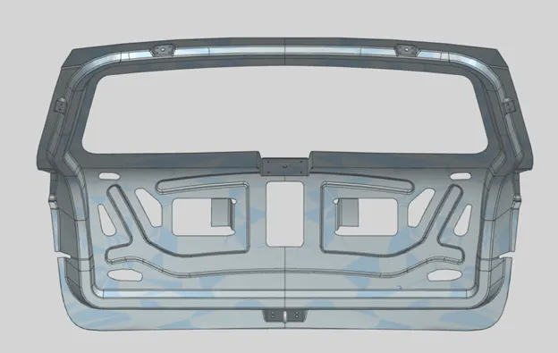
Fig 4b – Back
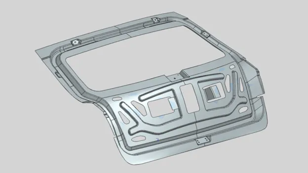
Fig 4c – Isometric
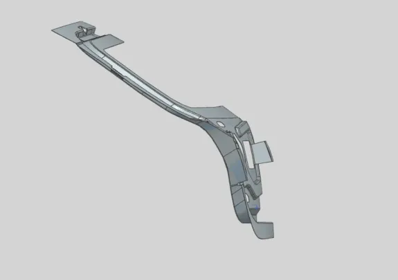
Fig 4d – Side
Tooling Direction:
To ensure adequate Tooling Draft, all embosses are given with respect to the Tool Direction for the part.
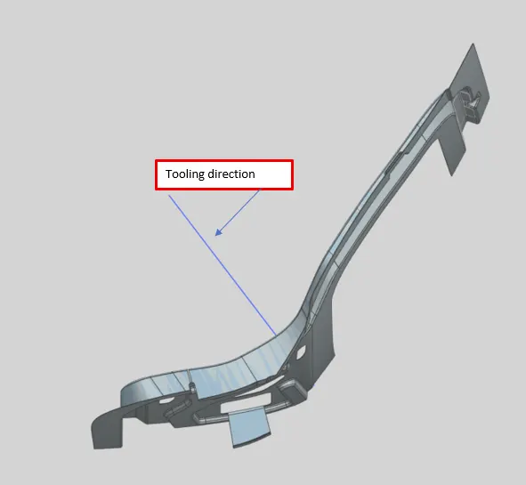
Fig 5 – Tooling Direction
- OUTER PANEL DESIGN:
We first corrected surface imperfections through use of Bridge Curves and other techniques. We also rounded sharp corners through use of Bridge Curves. We then hemmed the Upper and Lower Outer Panels and provided corner reliefs.
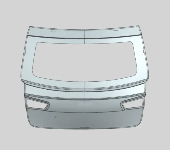
Fig 6a – Outer Panel (including upper and lower) – Front View
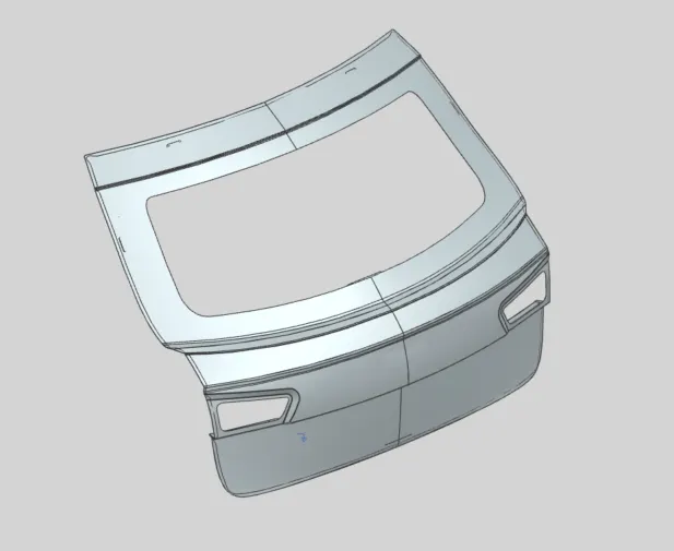
Fig 6b – Outer Panel (including upper and lower) – Iso View
Outer Panel Upper
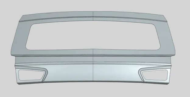
Fig 7a – Front
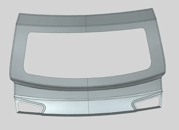
Fig 7b – Rear
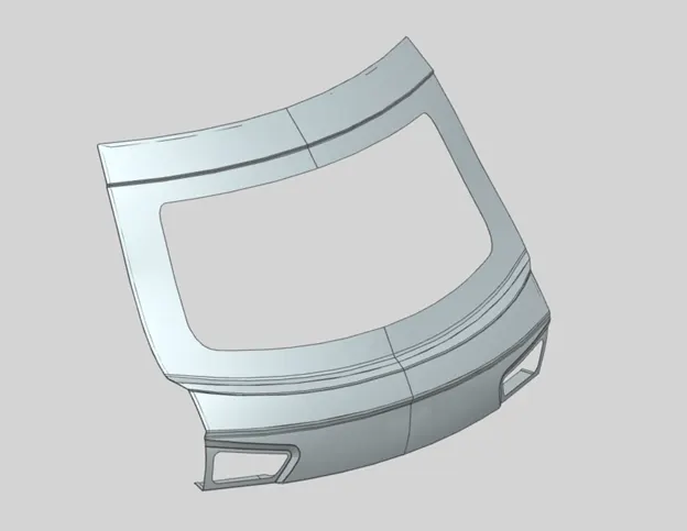
Fig 7c – Iso
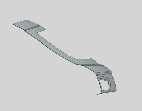
Fig 7d – Side
Outer Panel Lower
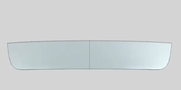
Fig 8a – Front
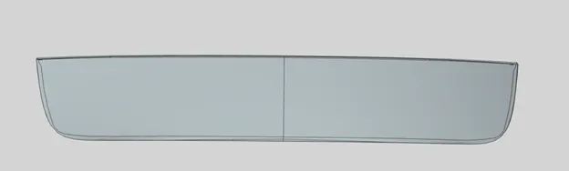
Fig 8b – Rear
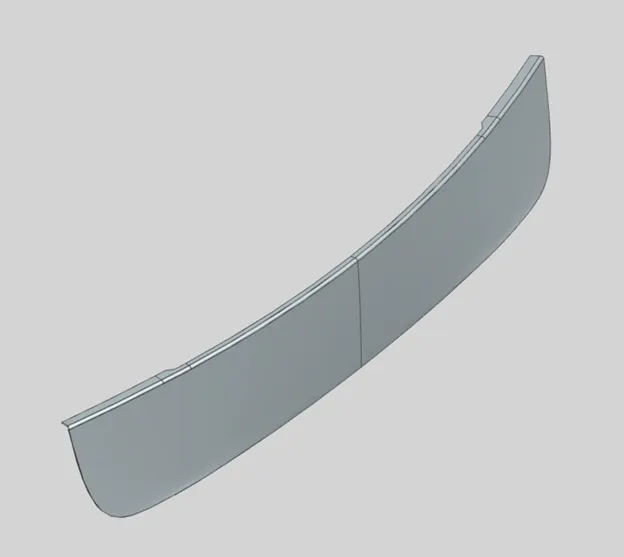
Fig 8c – Iso
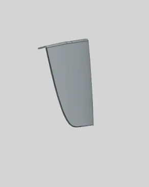
Fig 8d – Side
- HINGE REINFORCEMENTS:
The hinge reinforcements are 1.5mm in thickness, affixed to the inside of the inner panel, the side opposite the sealing rubber.
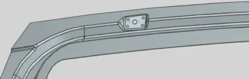
Fig 9a – Left side hinge emboss
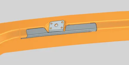
Fig 9b – Left side hinge reinforcement
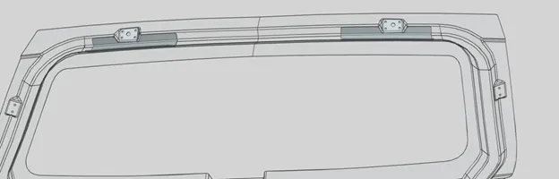
Fig 9c – Left and right side reinforcements
- WIPER MOTOR REINFORCEMENT:
The hinge reinforcements are 1.5mm in thickness, affixed to the inside of the inner panel wiper motor box.
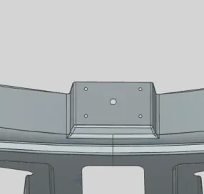
Fig 10a – Wiper Motor Emboss
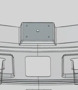
Fig 10b – Wiper Motor Reinforcement
- GAS STAY REINFORCEMENT:
The gas stay reinforcements are 1.5mm thick, and are mounted on the inside of the inner panel, on the side opposite the sealing rubber.
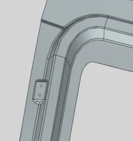
Fig 11a – Gas Stay Emboss
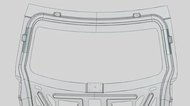
Fig 11b – Gas Stay Reinforcements
- STRIKER REINFORCEMENT:
The striker reinforcement is 1.5mm in thickness. It is aligned with the axis of rotation to provide a smooth fit when closing the door, and is mounted on the inside of the inner panel.
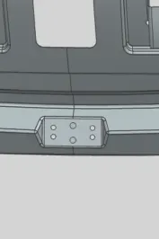
Fig 12a – Striker Emboss
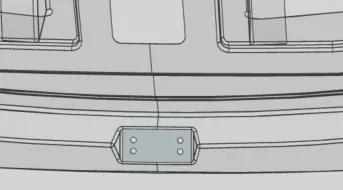
Fig 12b – Striker Reinforcement
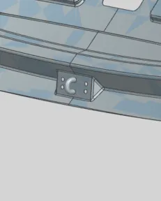
Fig 12c – Striker Inside View
- MASTIC SEALING STRUCTURE:
Mastic sealants add strength and improve NVH.
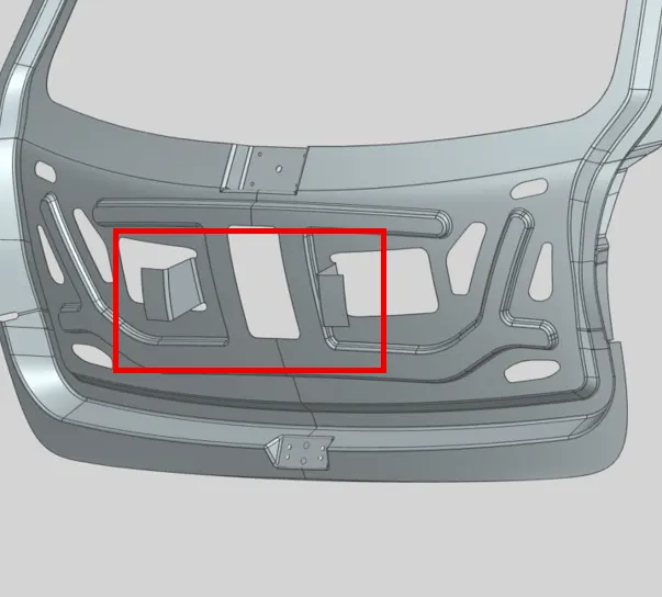
Fig 13 – Mastic Sealing Structures
- DRAFT ANALYSIS:
Draft analysis was performed to verify manufacturability, with cut-off at 7 degrees of Draft. The parted passed the draft analysis criteria.
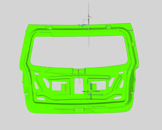
Fig 14 – Draft Analysis
.
- HEMMING
Hemming is the process of joining two surfaces through use of rollers which bend the outer over inner part. Reliefs are provided in the corners to ease mechanical stress and improve longevity.
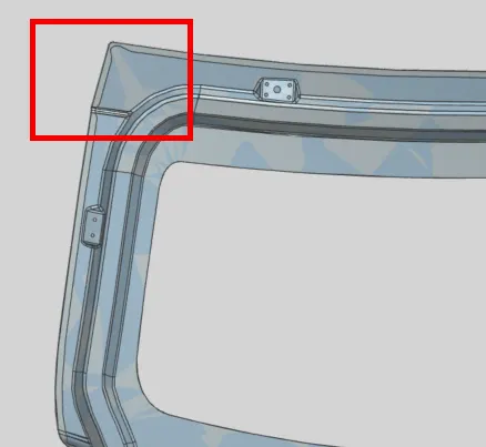
Figs 15a – Hemming Reliefs.
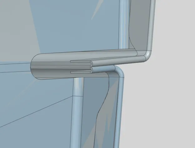
Fig 15b – Hemming at intersection of Upper and Lower Outer Panels
FINAL ASSEMBLY:
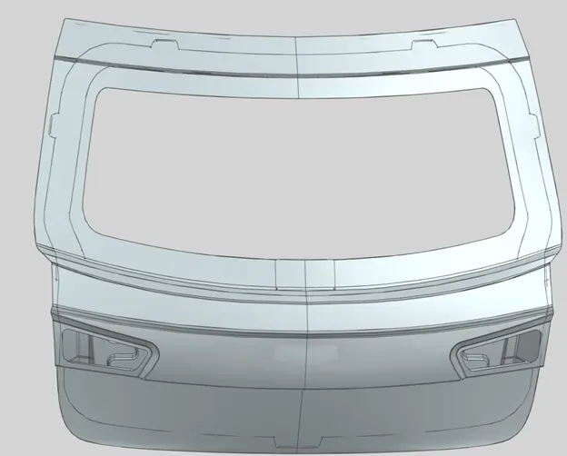
Fig 16a – Front
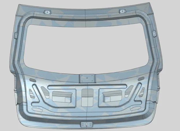
Fig 16b – Rear
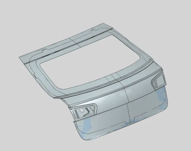
Fig 16c – Isometric
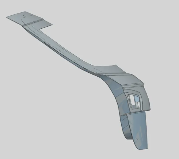
Fig 16d - Side
Conclusion
Design of the rear door assembly was successfully completed and verified for manufacturability.