Design of backdoor
Design of Backdoor
Objective:-
1.To Use the provided styling surface to come up with a back door design, use appropriate design methodologies, and provide the necessary reinforcements and embosses.
2.To Develop a detailed report for the Back door design by explaining the design methodologies and about the components developed in the design.
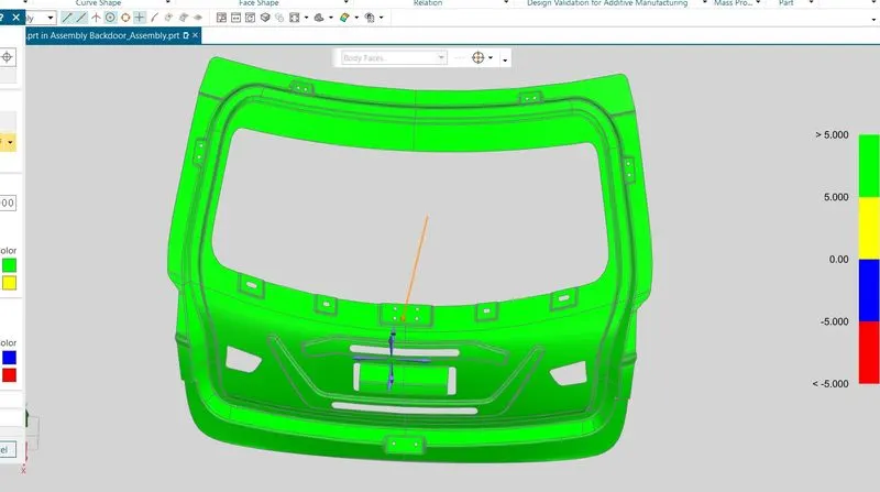
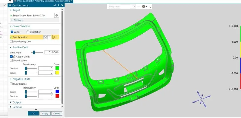
3.To Perform Draft Analysis along the tooling direction and include the snapshot in the report.
Introduction:-
A car door is a type of door opening, typically hinged on its front edge, but sometimes attached by other mechanisms such as tracks, for entering and exiting a vehicle. Doors most often integrate side windows for visibility from inside the car and can be locked to secure the vehicle.
Car doors may be manually operated or with power assist supplied by the vehicle. Powered doors or power doors may be found on minivans, luxury vehicles, or modified cars.
But here we will be discussing about the back door of a car there are many design considerations which are two kept in mind while designing a car back door which will be discussed further in the report.
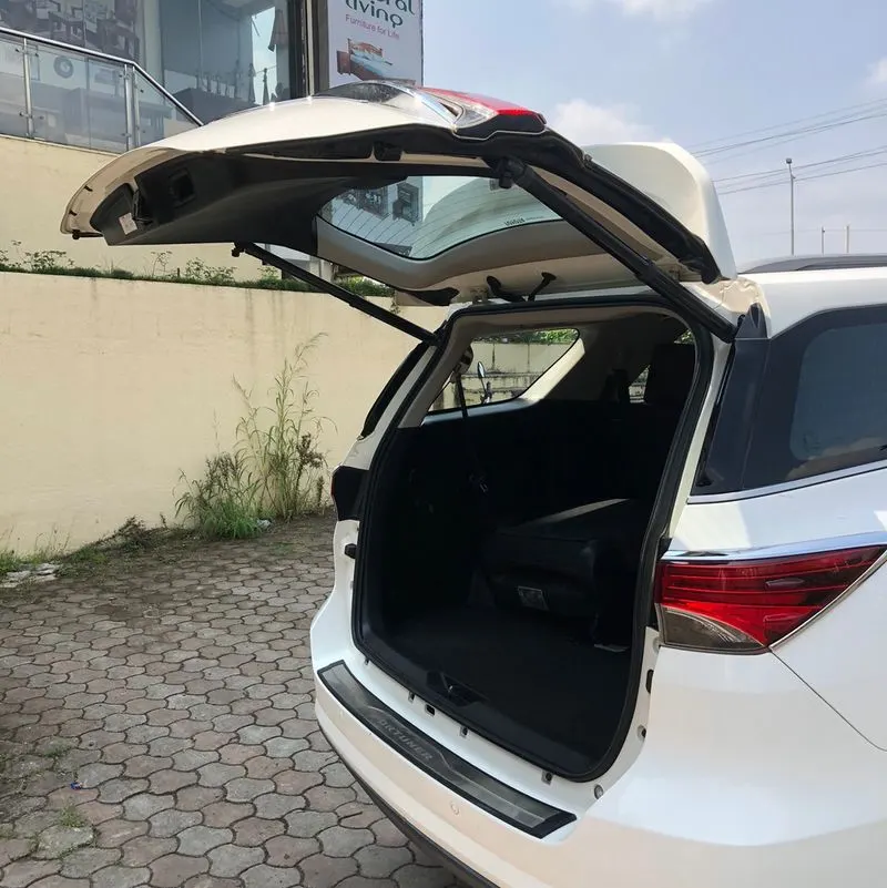
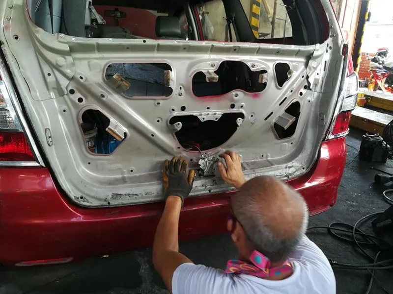
The upper image shows the innerpanel design of a car which is commercially used
Design Methodologies and Components:-
The components designed in this project are:
1. Back Door Outer Panel
2. Back Door Inner Panel
3. Hinge Reinforcement LH and RH
4. Gas Stay Reinforcement LH and RH
5. Wiper Motor Reinforcement
6. Striker Reinforcement.
The above components are shown in the below image
Procedure:-
1. Styling Surface
The styling surface is the surface which is provided as input in order to design the back door as per requirement of the customer.
The below image shows the input styling surface:
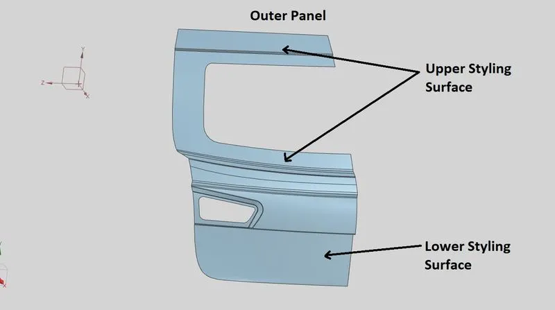
The above surface analysed and it was observed that the surface provided was having uneven surface quality.
The surface quality of the above class A surface was improved at the required positions using bridge curve and through curve mesh feature to improve the surface quality and then make the outer and inner panel of the back door panel.
2. Back Door Inner Panel
Determination of Tooling Axis:
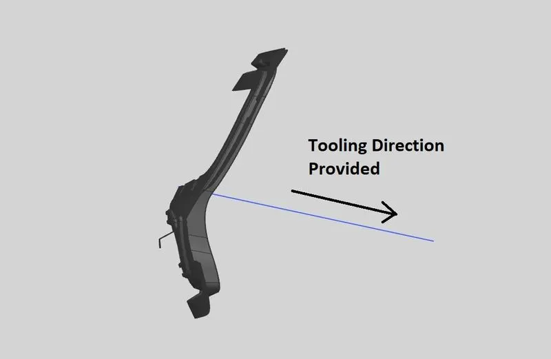
The tooling axis plays an important role while making a component. It is the axis of line along which the component will be extracted after the component is been moulded.
In this project the tooling axis is made by making two lines touch the opposite ends of the styling surface and then a bisecting line is drawn between these two lines to determine the tooling axis line.
The below image shows the tooling direction line:
Embosses:
In order to provide strength to the inner panel various embosses are designed on it to fix the reinforcement on the inner panel firmly.
Determination of emboss shape and direction:
As the back door open and closes in the upward and downward direction, during this time force is generated on it which might effect the durability of the back door panel. This generated force is dissipated in the outwards direction with the help of creating an emboss in the Y shape.
The below image shows the V emboss
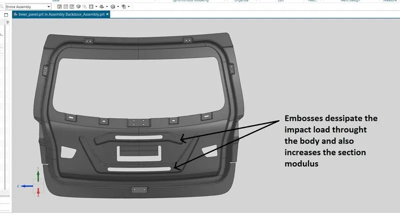
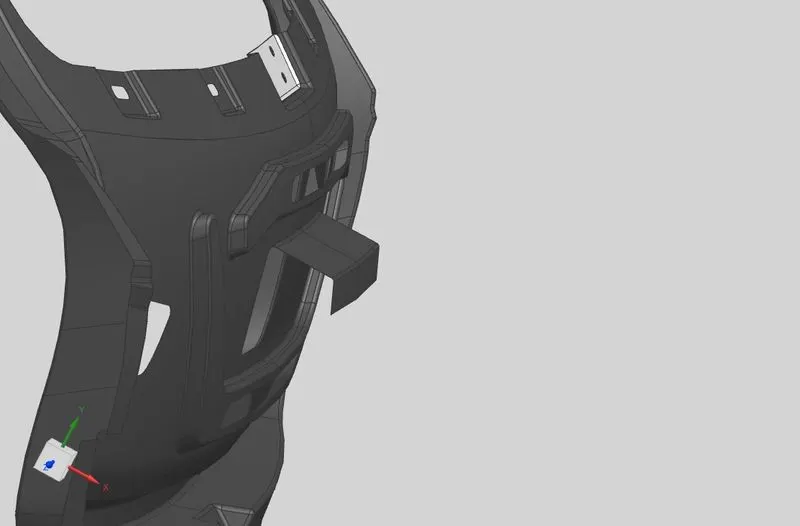
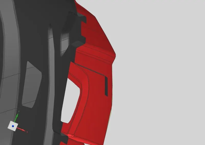
In order to firmly fix the outer panel to the inner panel a mastic extension flange is protruded towards the outer panel direction so that mastic can be applied on it and then the outer panel and the inner panel will have more strength in the middle portion and stick with each other firmly.
The above image shows the position of the flanges on the back door inner panel.
1. Hinge Emboss
Hinges will be placed on the top side of the inner panel in the left and right side. In order to fix the hinge to the inner panel embosses are designed on the back door inner panel.
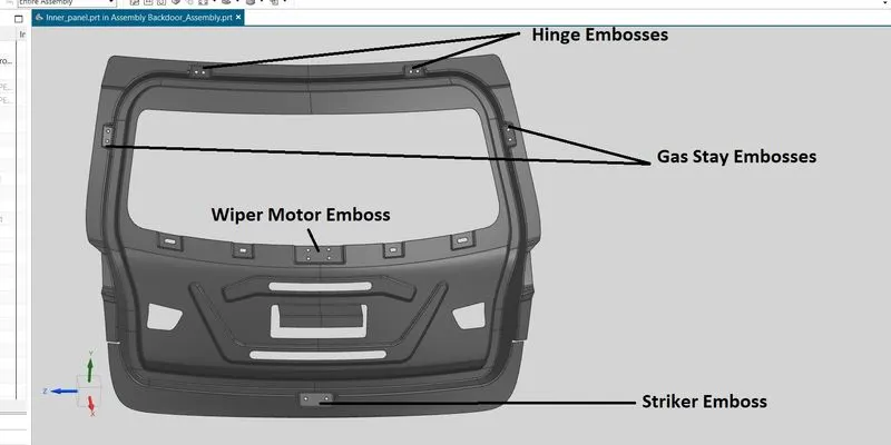
2. Gas Stay emboss
Gas stay is the component which is used to lift and lower the back door automatically with the help of pressing a button. This is placed on both the left and right side of the back door.
3. Wipe Motor Emboss
The wipe motor emboss is designed at the middle of the back door where the wiper motor will be placed on the back door. In order to clean the glass of the back door this mechanism is used on the back door.
4. Striker Emboss
This emboss is designed at the bottom portion of the back door. This system is used for locking the back door to the car.
Reinforcements
Reinforcements are the components which are used to add strength at a particular region.
The reinforcements designed for the back door are:
1. Hinge Reinforcement LH and RH
2. Gas Stay Reinforcement LH and RH
3. Wiper Motor Reinforcement
4. Latch and Striker Reinforcement
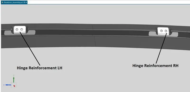
1. Hinge Reinforcement
The Hinge reinforcement will be placed on the embosses of the hinges which will enable it to fix the reinforcement firmly to the back door at required position.
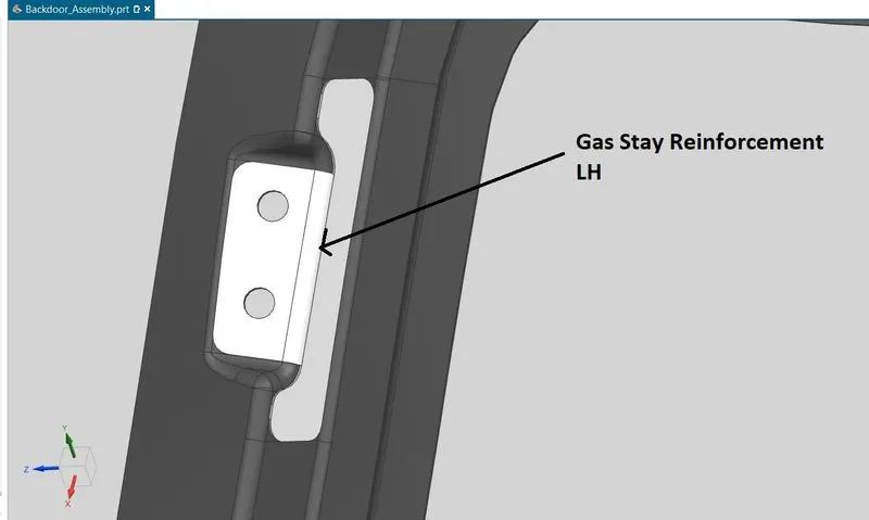
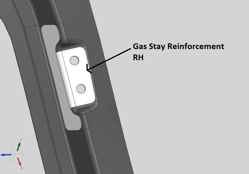
2. Gas Stay Reinforcement
Gas Stay reinforcement are designed to provide strength to the region where the back door will get opened and closed with the help of gas stay rods. For the purpose of durability these reinforcements are placed where the gas stay will be fixed with the back door panel.
3. Wiper Motor Reinforcement
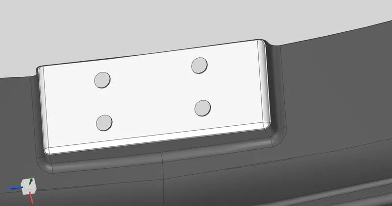
Wiper Motor Reinforcement is placed at the middle portion of the back door to provide strength in this region for the placement of wiper motor.
4. Latch And Striker Reinforcement
In order to place the latch at correct position a trajectory is made so that the back door is opened and closed following a trajectory without facing any obstacles. A circular sketch is drawn first to and which will show the trajectory of the path that the back door will follow while opening and closing, the latch position will be perpendicular to this circular trajectory at all the positions of the movement of the back door.
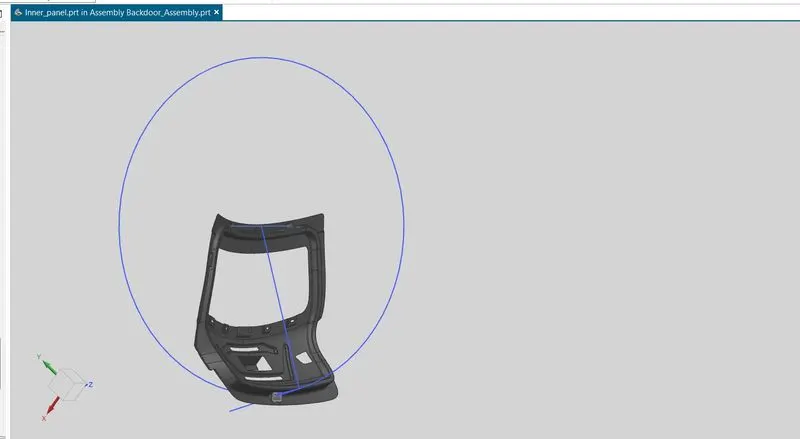
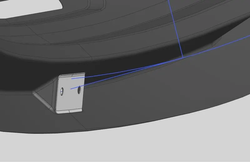
From the above image we can observe that the latch is designed perpendicular to the circular trajectory which will enable the back door to open and close freely.
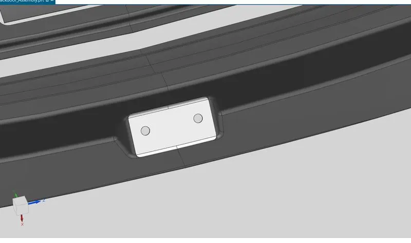
In order to provide strength in this region a latch reinforcement is placed which is shown in the below image:
Hemming Flange and Region
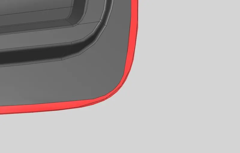
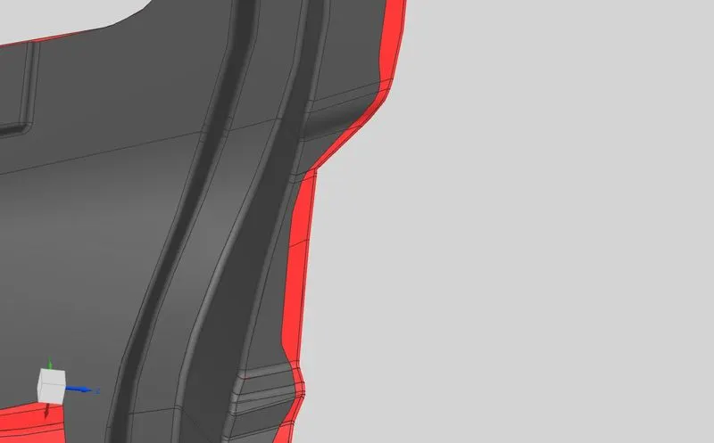
The back door outer panel will be fixed with back door inner panel with the help of hemming which will be done on the outermost edges of the outer panel. In this process the surface is bend and rounded around the inside surface so that it firmly holds the inside panel. Along with this mastic solvent will also be inserted inside this region for firmly sticking the outer panel with the inner panel.
The below image shows the hemming region designed.
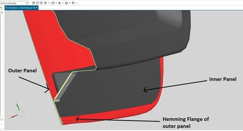
From the above image we can observe that the back door outer panel edges are rounded around the inner panel near the boundary region.
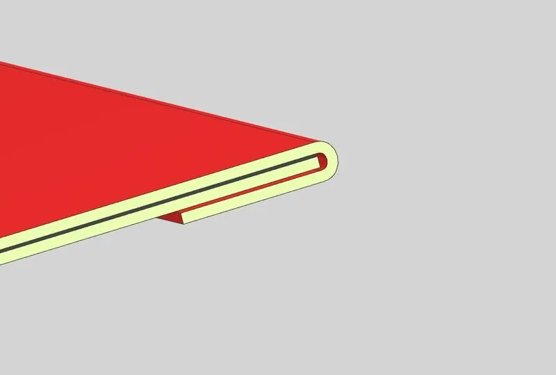
The above image shows how the hemming region looks around the boundaries.
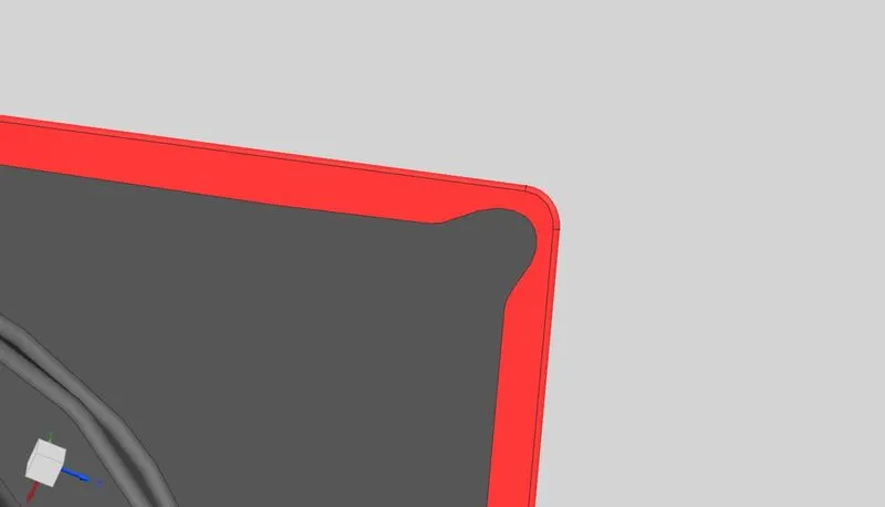
Corner Relief are also provided at the corners so that the hemming can be easily performed in all the regions.
Mastic Regions
To join the upper panel and the inner panel Hemming is used in the periphery but to make them join in between and at the middle portions they are join with the help of mastic sealants as spot welds are not used because they will hamper the aesthetics of the car body. To apply mastic and to make them join 5mm gap is provided between the two surfaces so an additional flange is created in the inner panel to join upper panel with the help of the mastic sealants.
Below is the image attached for the reference
Draft Analysis
In order to manufacture the part certain operations are done like deep-drawing, stamping etc. They require tool to operate the manufacturing but every tool and die has there specific opening angle and tooling direction to make the part smoothly and to make higher tool life. So to satisfy the tool opening angle and tooling direction the designed part is designed in accordance of it. In NX CAD there is a feature which analyse it. It is called Draft analysis so the draft analysis is performed in the design and the reference images are attached in the report..
Conclusion
The backdoor is designed with all the design considerations with proper reinforcements and draft analysis with attached images.
Report Prepared by
Rishabh Soni