Design of backdoor
PROJECT REPORT
CAR TAIL GATE DESIGN & DEVELOPMENT
SWAROOP S THAKUR
Introduction
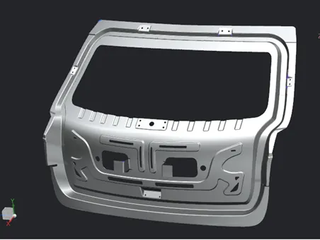
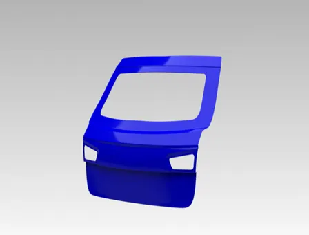
In this project I designed a tail gate BIW of a hatchback from the styling surface received from styling department. Similar to hood and side doors, tail gate is a swinging/closure commodity. It is a very critical part of the vehicle considering the safety of passengers and pedestrians. It should be also designed considering the luggage volume, wiper motor, plastic trims, wirings, latch and striker mountings etc. without compromising the strength of the part. Usually steel and aluminium are used for the component as materials. Aluminium is mostly used as a casted part, with varying thickness. So it doesn’t need any additional reinforcement components for hinge and other parts. Aluminium can reduce the overall weight of the component. But it is costly. Steel is used with deep drawing process with uniform thickness for manufacturing, with a lesser cost but causes increased weight of the component. Here we are supposed to be using steel as material. I developed the outer panels, inner panel, and various reinforcements for hinge, gas stay, wiper motor, latch and striker etc., after necessary study and analysis of the styling surface, following the industrial standards and methodologies. Catia V5 was used for the design stage. Here the backdoor is supposed to be fixed on the roof with necessary hinges and gas stays on side panels. Embosses were provided for added strength and it was designed in a way to handle the abuse and rear collisions in a better manner. Various basic holes and slots were provided for jigs, wiring, tail lamp housing and also for mounting plastic trims, latch, gas stay, hinges, wiper motor etc. Draft analysis was performed with 7 degrees of minimum draft angle to check whether it satisfies the deep drawing requirements.
Table shows the difference in weight comparing Aluminium and steel for a same back door
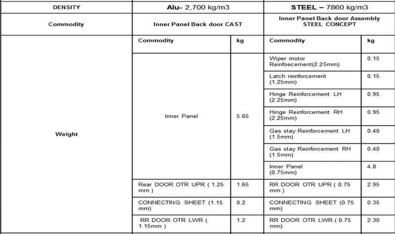
Total weight reduction by using Aluminium: 4.7 kg
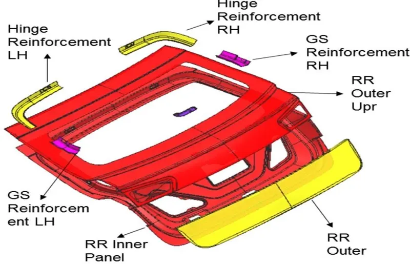
Components:
- Outer panel upper
- Outer panel lower
- Inner panel
- Hinge reinforcement LH
- Hinge reinforcement RH
- Wiper motor reinforcement
- Gas stay reinforcement LH
- Gas stay reinforcement RH
- Latch reinforcement
Major Design factors to be considered:
- Rear visibility
- Material
- Design of main emboss for better strength and safety
- Hinge position
- Latch position
- Gas stay position
- Deep Drawability
- Hemming
- Holes for various purposes
- Pedestrian and Passenger safety
Outer panel upper and lower
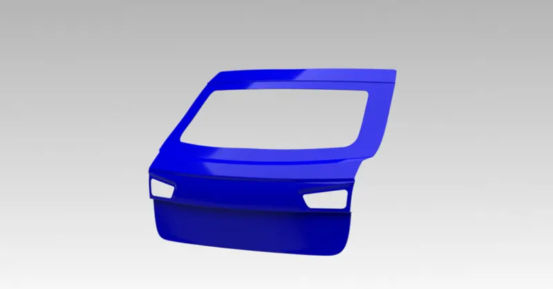
Outer panel upper part
It is developed from the styling surface. First of all the styling surface is analysed for rectifying if any issues are there. If there is any issues regarding the manufacturability, safety etc. are there, engineers will prepare a report about the same and send it back to the styling team for rectifying them at the initial stage itself. The thickness of the part ranges from 0.65mm to 0.75mm. It is supposed to be joined with inner panel using hemming and mastics.
The outer panel lower part is also prepared through the same procedure. For some cars the outer panel will be a single part instead of dividing them into two or three. It depends on various factors such as manufacturability.
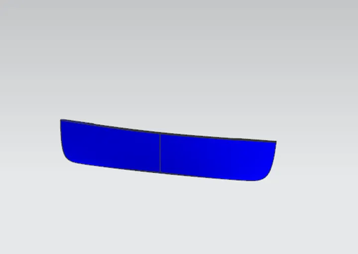
Outer panel lower part
Inner panel
Inner panel is designed to provide sufficient strength to the backdoor. Various embosses and reinforcements are provided on the inner panel for that purpose. The thickness of inner panel and additional reinforcement components ranges from 0.65 mm to 0.75 mm. It is designed after considering and analysing various load conditions such as slamming the backdoor, hanging, collisions etc. Sealing flange is provided on the inner panel for proper tight enclosure of backdoor, so that it prevents the entry of water and other elements entering inside by firmly closing the door. Various features like wiper motor mount, Plastic trim mounts, latch and striker mounts and passages for wirings, jig and fixture slots etc. are provided on the inner panel. The gas stay mounting point on tail gate depends on the weight of the door, type of gas stay used etc. It’s kinematics should be properly calculated as otherwise the tail gate motion will not work properly.
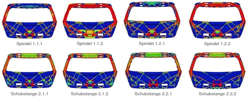
An example of analysis of various optimised designs for strength and safety
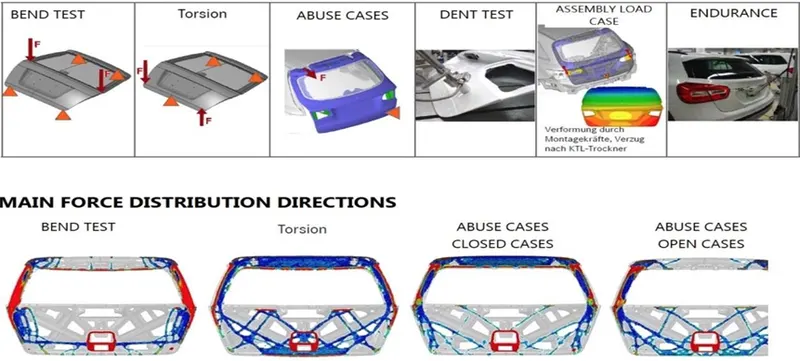
Inner panel – Results of tests based on various cases (Example)
Here we are going to manufacture the inner panel using deep drawing operation and material used is steel. So a minimum draft angle of 7 degree is applied on every features such as embosses, sealing flange etc. on the panel with respect to the tooling axis.
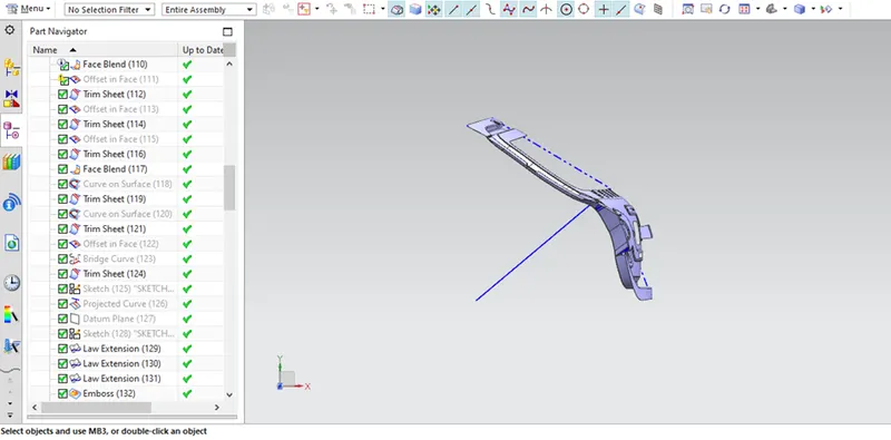
Tooling axis
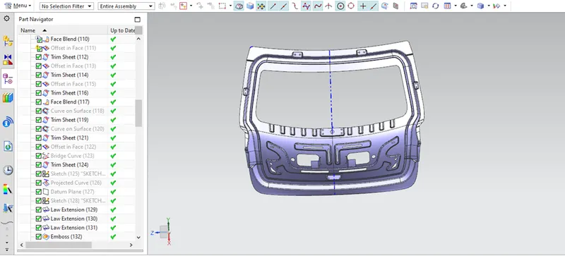
Inner panel
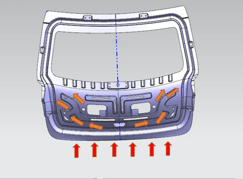
Embosses designed to dissipate the impact forces away from passengers
For proper closing of the tail gate, the latch must be always perpendicular to the trajectory of swing of door on hinges. For that purpose the latch mount surface on inner panel must be perpendicular to the same. It is shown below.
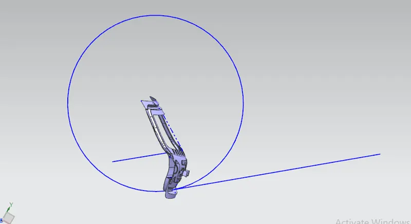
Draft analysis
If the draft angles are not appropriate it will also cause the premature wearing of core and cavity of die, which is not good for manufacturing as it will reduce the life of die and also affect the finishing of the part produced after a number of cycles of manufacturing.
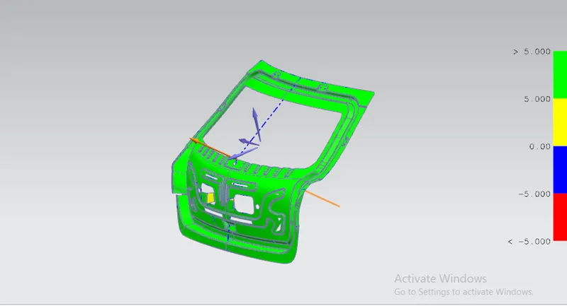
Draft analysis with minimum 7 degree angle
Local Reinforcements
Various reinforcements are locally applied on various regions such as hinge area, gas stay mount area, wiper motor mount area, latch mount area etc. The thickness of the reinforcements ranges from 0.65 mm to 0.75 mm. Those reinforcements are spot welded to the inner panel at necessary regions. This will improve the moment of inertia of the inner panel on those regions thus ensuring overall better strength of the backdoor. Various reinforcements designed for this purpose are shown below.
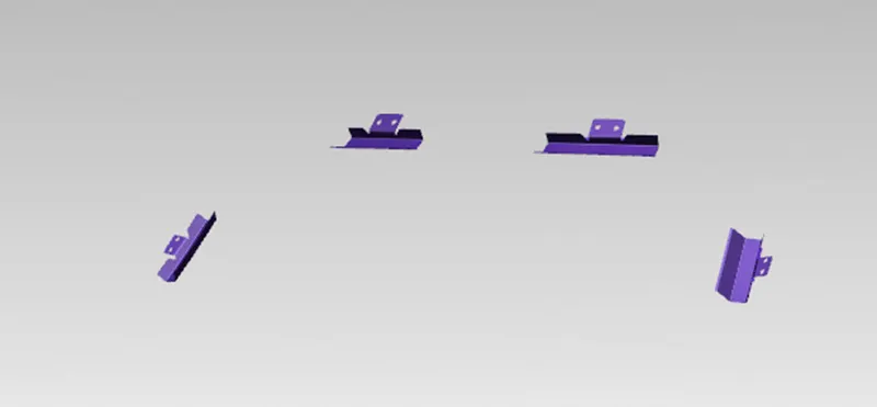
Hinge, gas stay, reinforcements
Tail gate assembly
Inner and outer panels are assembled together by an operation called hemming after welding all the reinforcements on inner panel. Also mastic sealants are applied on the hemmed regions at a thickness of 0.2 mm on each side. The outer panel is held by the inner panel at the centre using mastic sealant at a thickness of 4mm as shown below. Thus better NVH is result is obtained.
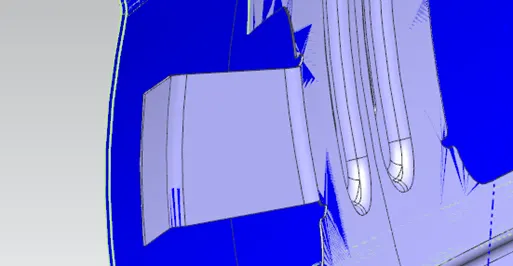
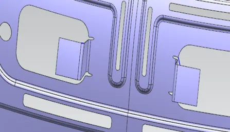
Both upper and lower outer panels are joint together by braze welding. Brazing is a metal- joining process in which two or more metal items are joined together by melting and flowing a filler metal into the joint, with the filler metal having a lower melting point than the adjoining metal. Brazing differs from welding in that it does not involve melting the work pieces. Brazing differs from soldering through the use of a higher temperature and much more closely fitted parts than when soldering. During the brazing process, the filler metal flows into the gap between close-fitting parts by capillary action. The filler metal is brought slightly above its melting temperature while protected by a suitable atmosphere, usually a flux. It then flows over the base metal (in a process known as wetting) and is then cooled to join the work pieces together. A major advantage of brazing is the ability to join the same or different metals with considerable strength.
Hemming:
Hemming is a forming operation in which the edges of the sheet are folded or folded over another part in order to achieve a tight fit. Normally hemming operations are used to connect parts together, to improve the appearance of a part and to reinforce part edges. In car part production, hemming is used in assembly as a secondary operation after deep drawing, trimming and flanging operations to join two sheet metal parts (outer and inner) together. Typical parts for this type of assembly are hoods, doors, trunk lids and fenders. The accuracy of the hemming operation is very important since it affects the appearance of the surface and surface quality. Material deformations, which occur during the hemming process, can lead to dimensional variations and other defects in parts. Typical hemming defects are splits or wrinkles in the flange, material overlaps in the corner areas or material roll-in. This is why it is important to use simulation tools in order to, on the one hand, better understand the hemming process and, on the other hand, significantly reduce the number of “trial and error” loops during tryout und production.
Types of hems:

Stages of roller hemming:
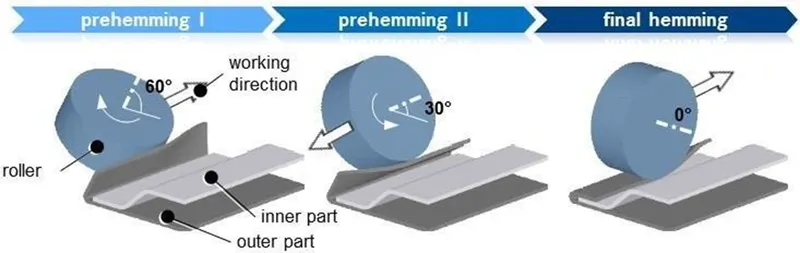
Roller is guided by an industrial robot to form the flange.
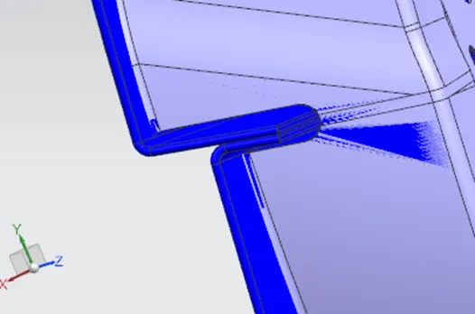
While hemming The gap between the inner panel surfaces and outer panel surfaces weremaintained with 0.2 mm distance.The distance between the bend of the outer sheet metaltotheedge oftheinnerpanelisabout2mm.
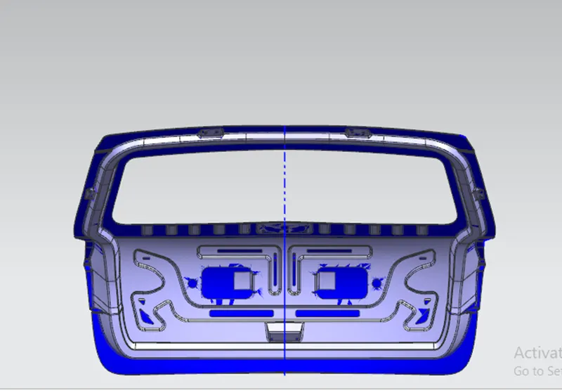
Factory tail gate assembly line example
( NOTE: Images are from different sources and different cars )
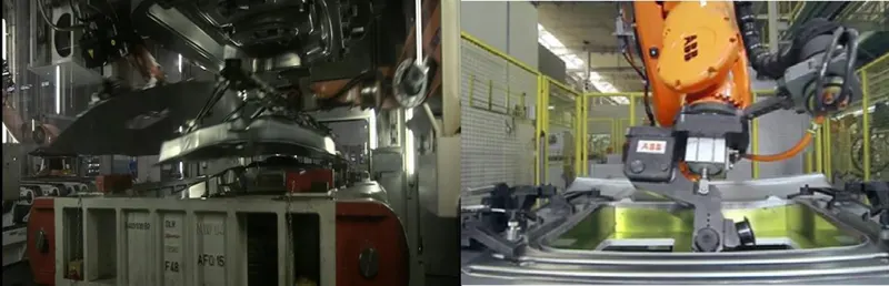
Stamping tail gate inner panel Roller Hemming robot working on tail gate
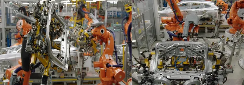
Robotic arms working on tail gate inner panel
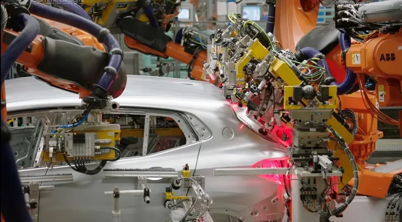
Robots mounting tail gate
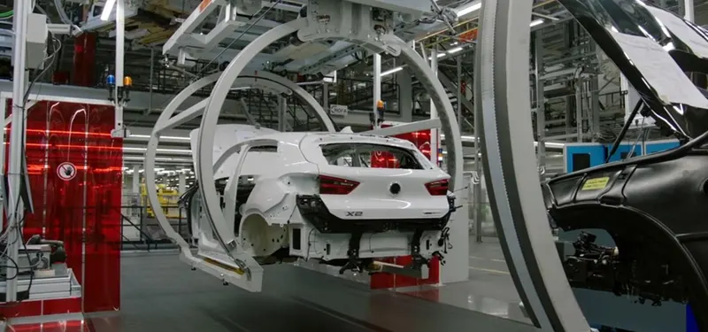
Tail gate inner & outer panels mounted on car
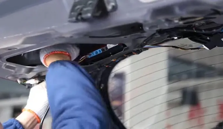
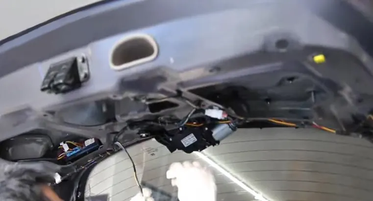
Assembling wiper motor on inner panel
Conclusion:
Thus the tail gate of the car was successfully designed by following the industrial standards and methodologies.
Report submitted by; Swaroop S Thakur