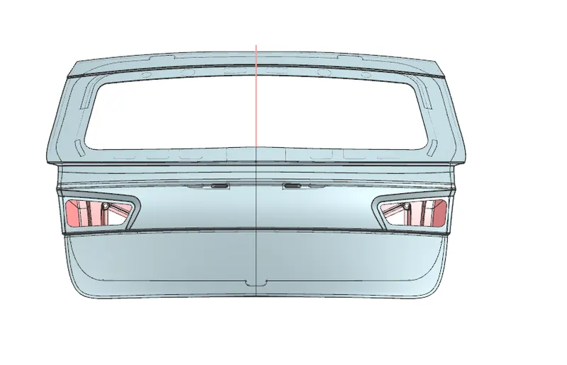
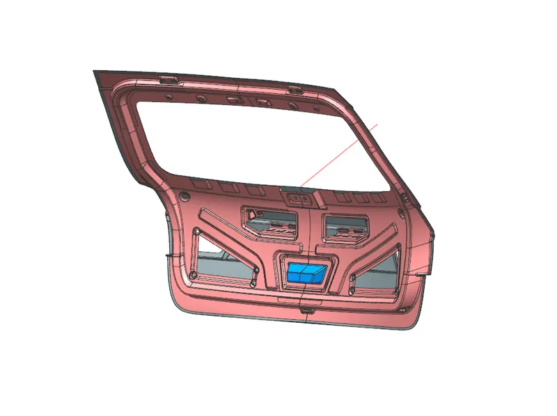
Design of backdoor
Aim: To develop Tail Gate assembly using CAS surface given on UG NX cad tool
Introduction:
Tail Gate/ Back Door:
A Door is a hinged part which is used for entry and exit of the vehicles. Backdoor are one of the type of door of the vehicle which are located next to the passanger seat which provides access to the luggage compartment. In the most of the cars, these back door are operated with the help of gas stay which in turn reduces the effort required to lift the door. Some luxuary cars have powerd backdoor which in turn is driven by an electric motor. This kind of system is also called a powered trunk lid system. Some SUVs we use tail gate as door for to enter inside vehicle as it has seating comparment in rear side also. Tail gate is considered very important part as during traffic many times vehcile collide to the reat of side of vehicle so it is designed according to that criteria, it also has mountings for rear wiper and rear tail lamp and contains rear glass which plays important role in deciding rear visbilty
Type of Door mountings
Top mounted:
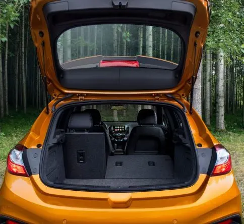
In this type door is mounted on top with help of hinge as shown in above example hinge mountings are provided on the BSO and Rear Roof bow joinery and other side of hinge mounted on the inner panel.
Side Mounted Door:
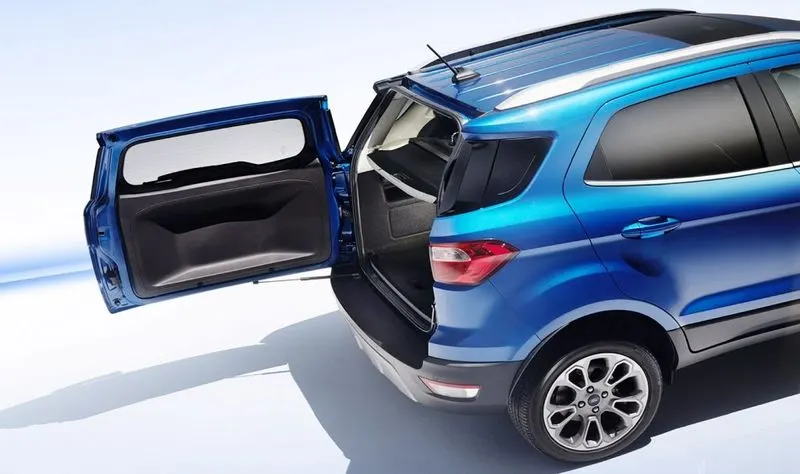
As the name signifies the side mounted doors are the one which is used in the van type MPVs, SUVs, pickup truck vehicles. These side mounted doors or barn doors are a lot easier compare to top mounted doors. These doors are generally smaller in size and can be easily accessed. It is a lot easier to load and unload items in the side mounted doors. It is usualy used when there will be seating compartment.
Bottom Mounted Door:
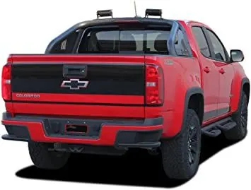
This bottom type type backdoor system are used in the car type such as pickup truck and some luxuary SUVs. These are the most convenient type of back door in which the bottom split is used as a support or even as a table for the tour going people.
Tail Gate Assembly Consists of
1. Outer Panel
2. Inner Panel
3. Hinge Mtg Reinforcement
4. Striker Mtg Reinforcement
Design Methodology
After recieving CAS from styling team we start preparing model. We take surface from roof team (if not available then we prepare them ourselves by considering joiner of rear roof bow, roof and tail gate inner panel) and then we prepare sealing surface which we can give further to BSO team as seal is mounted on BSO and is compressed during Tail Gate close condition.To prepare sealing surface we derive it from CAS itself.
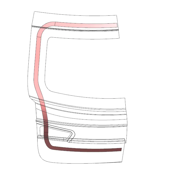
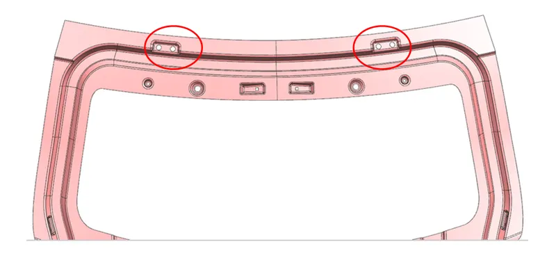
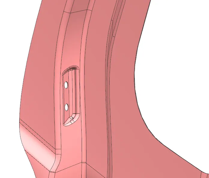
After preparing Sealing surface we begin developing the inner panel basic structure of inner panel is decided as per the rear visibilty and other components that are mounted on the panel we have to provide Wiper Unit mountings on the panel along with Striker Assy moutings and other wirng harness clips mtg are also provided so we have to provide emboss and structure as per strength requirement.
For Cashworthiness: As rear crash is very common so we have to provide some provisons in our design to avoid much damage to passangers so emboss id provided in such a way that when force is applied it travels more towards side and absorbs the maximum energy and do not let it pass to passamger compartment. And also in botton side BOX section is provided to make sure section modulus is more and our panel does not get bend easily
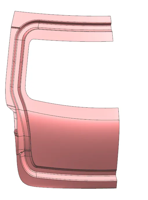
After embossing:
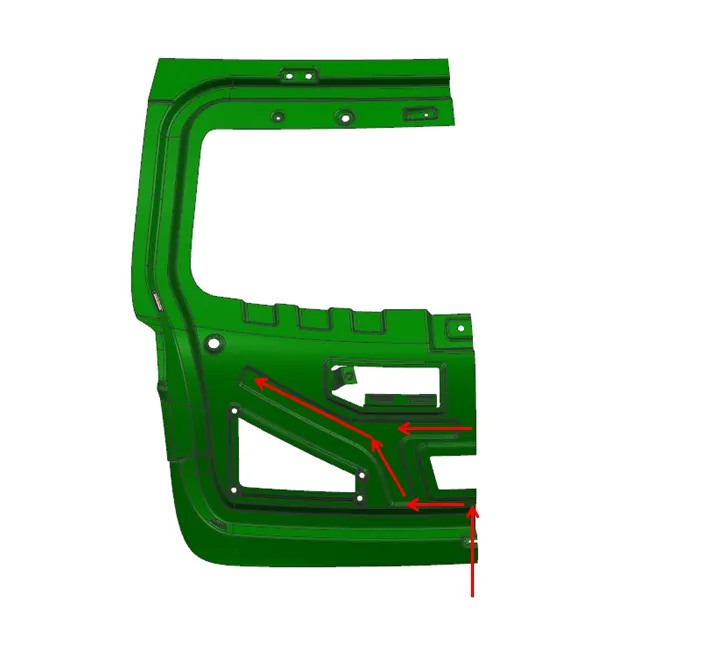
We provide cutouts in the lower side to maintain the CG of part in middle for stability and for sealant application we provide flanges which are kept at distance of 5mm from outer panel. Depression are made on flanges to fill the sealent which provided stiffness and prevent NVH issues
Hinge Mtg Emboss:
Tie Rod Mtg Emboss:
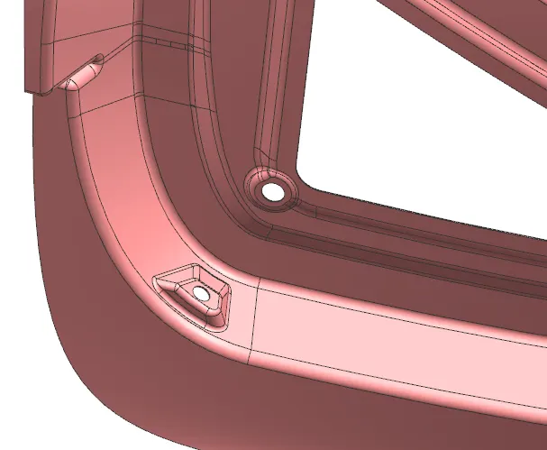
Bump Stop Mounting:
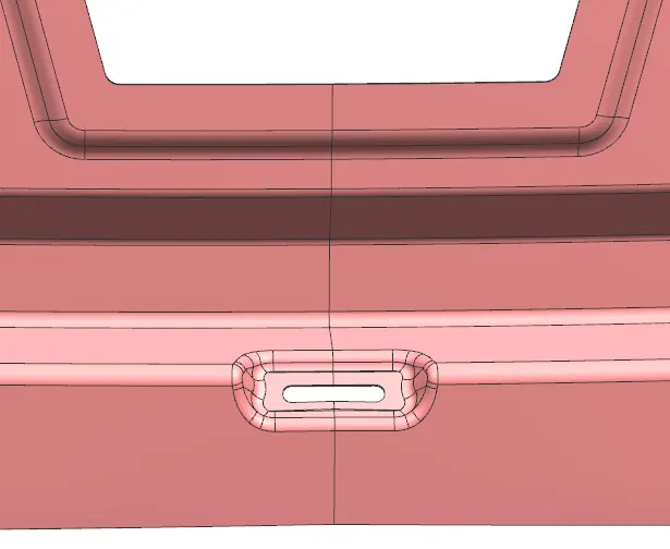
Water Drain Hole:
Final Inner Panel:
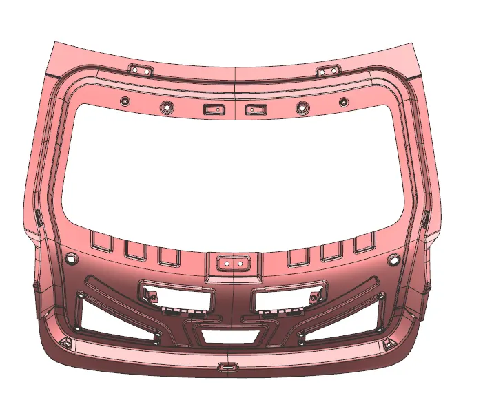
Hinge Reinforcement:
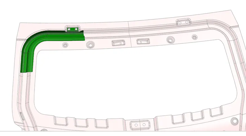
Tie Rod Reinforcement:
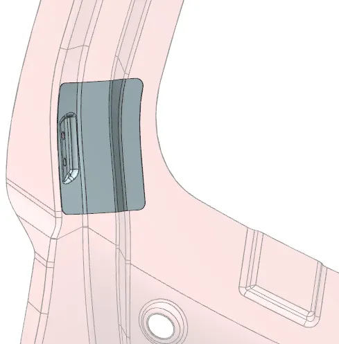
Striker Reinf :
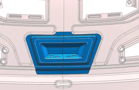
Final Inner Panel Assy:
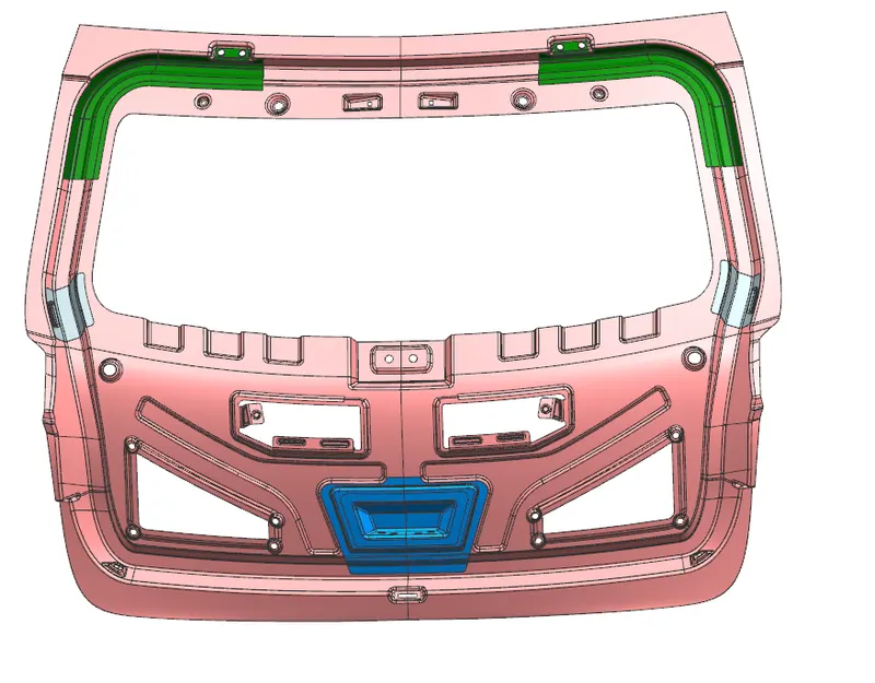
Outer Panel:
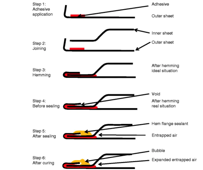
We add engineering features to CAS surface received we join inner panel with outer panel with hemming process so we need to add hem flange to Outer Panel:
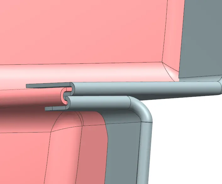
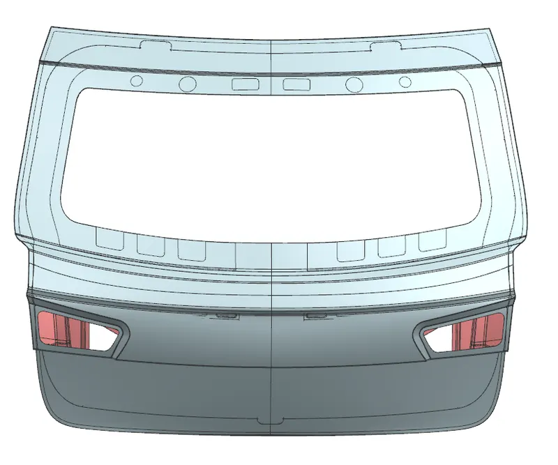
Hemming Process:
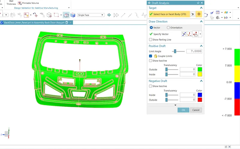
Draft Analysis:
While creating part we first decide to make tooling direction then we will do draft analysis so that our part can be cleared in tooling easily and there are no undercuts.
Final Model: