Design of backdoor
BACK DOOR DESIGN IN NX
OBJECTIVE: The main objective or intent of this project is to give us as idea about the back door of a car works and to design the various components of a car such as sealing flange, outer panels, inner panels, and various reinforcements.
INTRODUCTION
BACKDOOR: A back door is the door which is at the rear end of a car. It provides access for luggage compartment, more the width of the backdoor more will be the luggage space available. The back door is attached to the roof at the top and for purpose of leak proof sealing a sealing flange is used.
The backdoor is also called as tail gate. The image of a back door is as show in below figure,
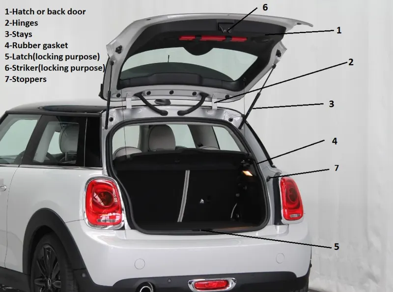
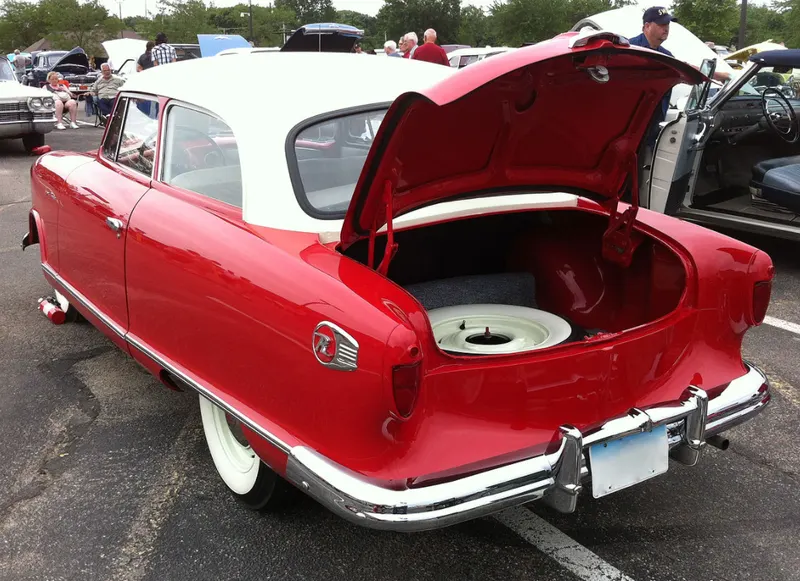
There are different types of back doors available in the market, the major types are as shown in below pictures
1.TOP MOUNTED: This is the type of back door which is widely used.
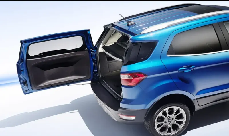
2.SIDE MOUNTED: The new age Ford Motor uses this kind of backdoor and is illustrated in the below figure,
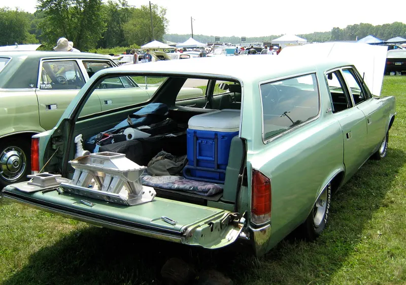
3.BOTTOM MOUNTED: this type of backdoors are rarely used in a car but it is widely used in three wheeled auto type of vehicles.
COMPONENTS OF A BACK DOOR
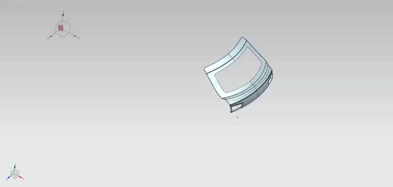
1.OUTER PANEL UPPER: the given surface in the challenge consists of outer panel upper position but in contains many disjoint and uneven surfaces and we are unable to sew the surface.
So, we have to repair the surface and sew them. for this first we have to hide the surface which causing the issue and by using bridge curve and studio surface or through curve mesh option we have to repair the surface and create a new surface and sew them. Make sure that all the corners and edges are smooth and fileted properly.
Now mirror the surface by using mirror geometry command through Zc axis and apply thicken by 0.75mm in downward direction.
The image of outer panel upper is as shown in below figure,
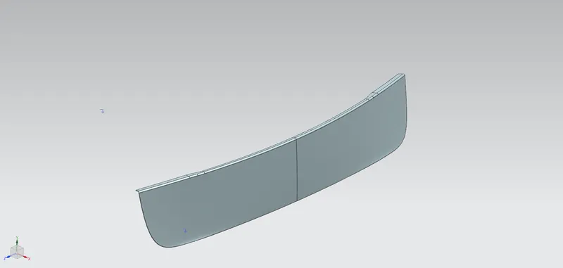
2.OUTER PANEL LOWER: The outer panel lower part is also given in the challenge itself and we have to use this surface to design inner panel of the backdoor and we have to hem the outer panel lower to the inner panel. the given outer panel is as like shown in below figure,
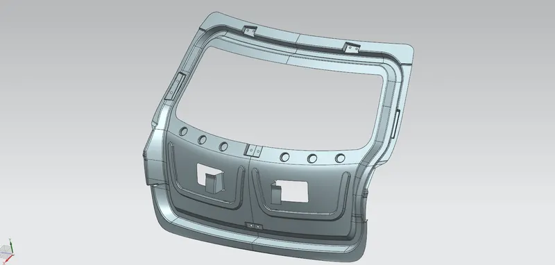
3.INNER PANEL: The inner panel is designed by using the two outer panels by offestting them to a required distance. a tooling direction vector is created inorder to determine the tooling direction and we have to use this vector fpr creating embosses on the inner panel. we have create different embosses in different manners to serve various purposes, the final look of inner panel are as shown in the below figure,
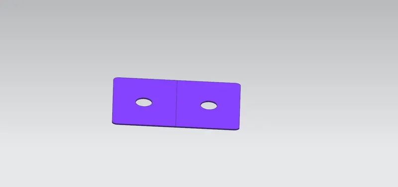
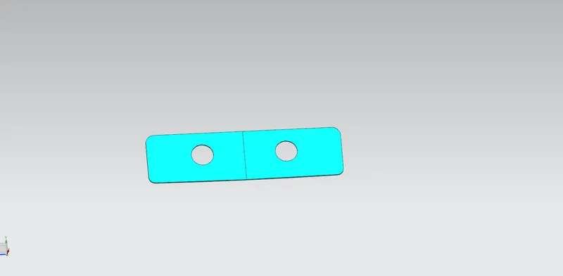
4.REINFORCEMENTS: There are different types of reinforcements in our back door design, they are designed by extracting the body from the inner panel and trimiing the extracted body to a required shapes and sizes. after trimiing the sheets we have to give some thickness to the reinforcements in a proper direction.
different types of reinforcements are
- hinge reinforcement
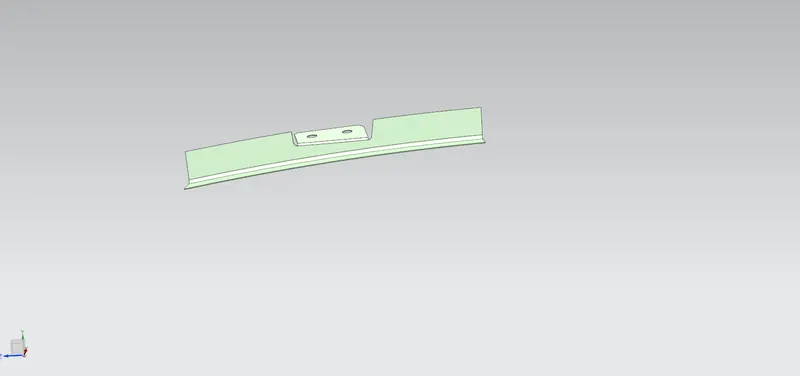
- gas stay reinforcement
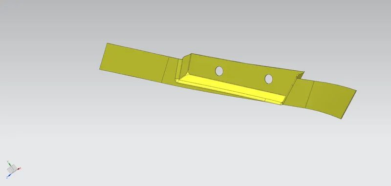
- wiper motor reinforcement
- latch and striker reinforcement
DESIGN APPROACH
STEP1: the first step is to download the skin data or class A surface of the back door.
STEP2: second step is to repair the given surface and sew the outer panel bodies into a single body
STEP3: the next step in this process is to design the sealing flange by using the outer panels
STEP4: design the inner panel after designing the sealing flange.
STEP5: the next step is to design embosses on the inner panel in order to increase the stiffness and strength and to dissipate the loads acting on it in case of collisions or accidents.
STEP6: create embosses on the inner panel to accommodate the reinforcements.
STEP7: create or design reinforcements
STEP8: last and final stage is to design the hemming to wrap inner panel and outer panel together.
DESIGN CONSIDERATIONS
1.the rear visibility should be great
2.the parts have to thickened 0.75 mm in proper directions
3.All the sharp corners have to be filleted properly
4.the design should be in such a way that there should be enough storage space for luggage’s.
MANUFACTURING PROCESSES
The main manufacturing processes that are used in manufacturing a back door are
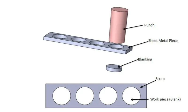
1.PUNCHING: Punching is a forming process that uses a punch press to force a tool, called a punch, through the workpiece to create a hole via shearing. Punching is applicable to a wide variety of materials that come in sheet form, including sheet metal, paper, vulcanized rubber, and some forms of plastic sheet. The punch often passes through the work into a die. A scrap slug from the hole is deposited into the die in the process. Depending on the material being punched this slug may be recycled and reused or discarded.
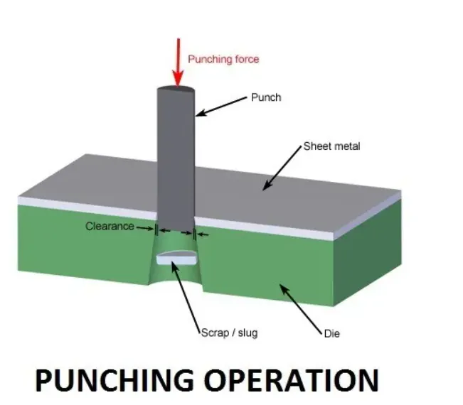
Punching is often the cheapest method for creating holes in sheet materials in medium to high production volumes.
2.BLANKING: When a specially shaped punch is used to create multiple usable parts from a sheet of material the process is known as blanking. In metal forging applications the work is often punched while hot, and this is called hot punching. Slugging is the operation of punching in which the punch is stopped as soon as the metal fracture is complete, and metal is not removed but held in hole.
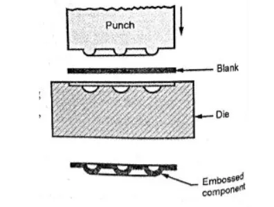
3.EMBOSSING: embossing is a stamping process for producing raised or sunken designs or relief in sheet metal design. This process can be made by means of matched male and female roller dies, or by-passing sheet or a strip of metal between rolls of the desired pattern. It is often combined with foil stamping to create a shiny, 3D effect.
The embosses in our case are
1.embosses on inner panel
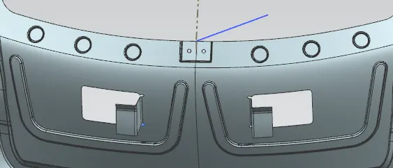
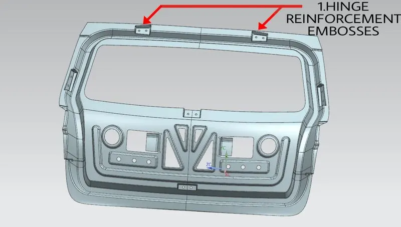
2.embosses for hinge reinforcement
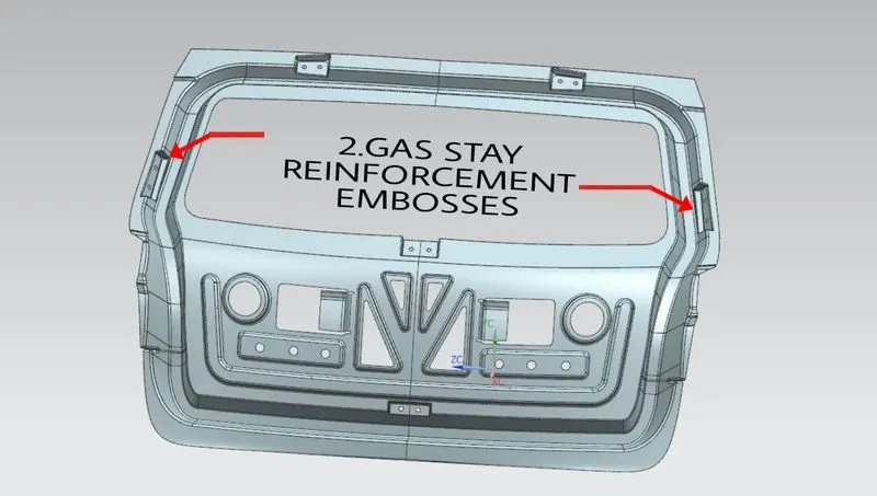
3.embosses for gas stay reinforcement
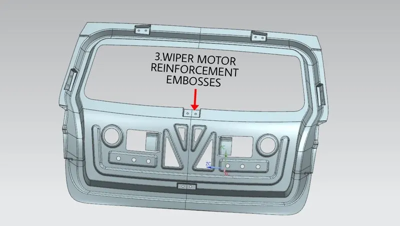
4.embosses for wiper motor reinforcement
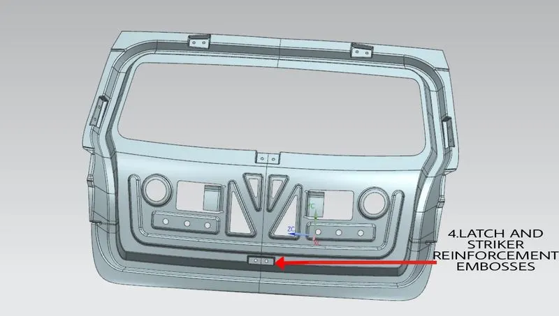
5.embosses for latch and striker reinforcement
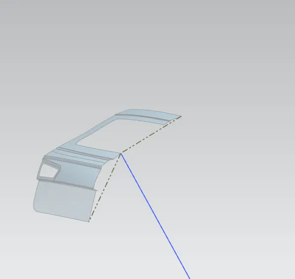
4.DEEP DRAWING: Deep drawing is a sheet metal forming process in which a sheet metal blank is radially drawn into a forming die by the mechanical action of a punch. It is thus a shape transformation process with material retention. The process is considered "deep" drawing when the depth of the drawn part exceeds its diameter. This is achieved by redrawing the part through a series of dies. The flange region (sheet metal in the die shoulder area) experiences a radial drawing stress and a tangential compressive stress due to the material retention property. These compressive stresses result in flange wrinkles (wrinkles of the first order). Wrinkles can be prevented by using a blank holder, the function of which is to facilitate controlled material flow into the die radius.
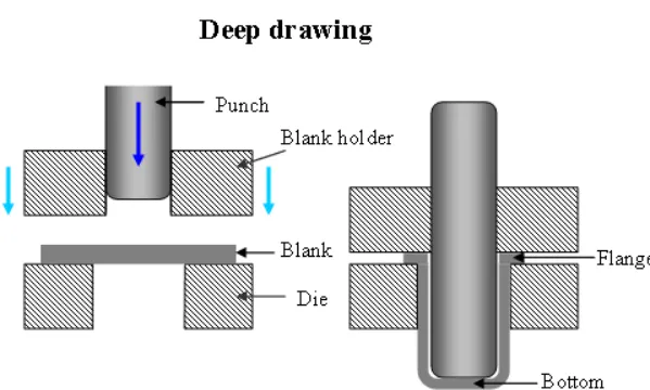
The deep drawing direction inour case is as shown in below figure,
5.HEMMING: Hemming is the process in which the edge is rolled flush to itself, while a seam joins the edges of two materials.
Hems are commonly used to reinforce an edge, hide burrs, and rough edges, and improve appearance.
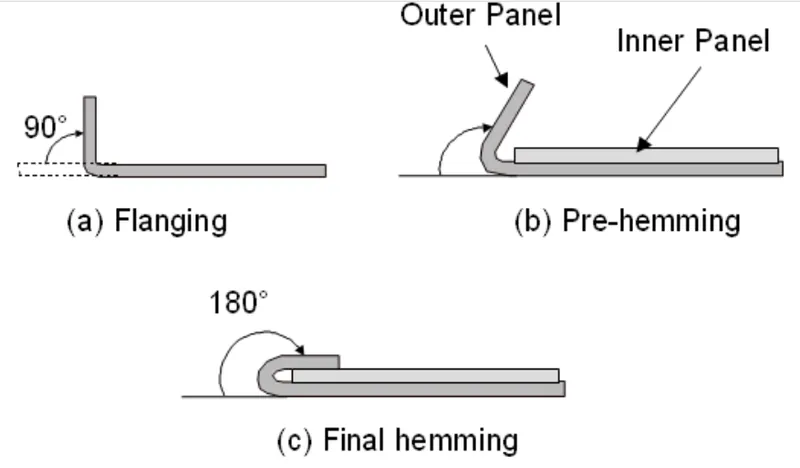
The hemming in our case is as illustrated in the below figure,
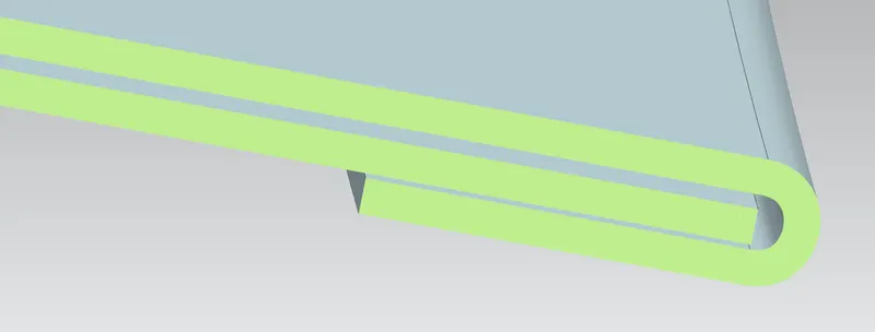
For hemming we have to offset outer panel to a distance of 2.65 in downward direction and by using swept and bridge curve commands we have to create a hem which covers the inner panel, the image of hem is shown in below figure,
EDGE CLEARNCE
The clearance on the hem on the edges of outer panel upper is given as shown in below figure,

The clearance on the hem on the edges of outer panel lower portion is given as shown in below figure,

From the above two figures we candetermine that all the four edges are provided with proper clearance required.
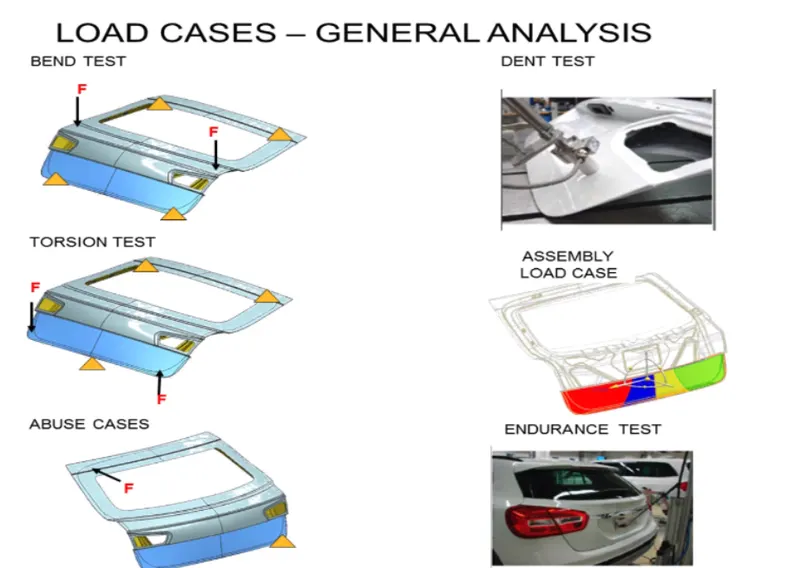
LOAD CASES
Different types of load cases on the back door of a car are as illustrated in the below figure, so we have to consider all the mentioned criterias in our design,
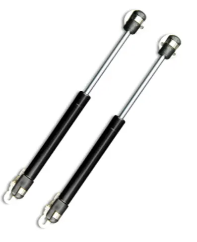
GAS STAY
GAS LIFT SUPPORT:
Gas charged lift supports are energy storage devices that create energy by compressing gas inside a cylinder. When closed, the energy is stored. When opened the energy is released to raise a hatch, hood, liftgate or trunk, holding them safely in an open position. Gas charged lift supports are sometimes incorrectly thought of as shock absorbers or struts, which instead absorb energy to control motion. Lift supports normally store a gas charge of 1,500 psi, therefore, they cannot typically be compressed by hand.
By design, all gas charged lift supports begin to fail over time. They are typically out of sight and out of mind…until they no longer function properly. Furthermore, they may work reasonably well one day and then not at all the next. The most common causes of failure include loss of gas pressure due to natural permeation, exposure to extreme temperatures and frequent use or cycling of the part. Replacement can also be expected if the vehicle is of five years of age or older. Lift Support usage can be broken into two categories: Automotive specific applications and Universal applications.
ASSEMBLY VIES OF BACK DOOR
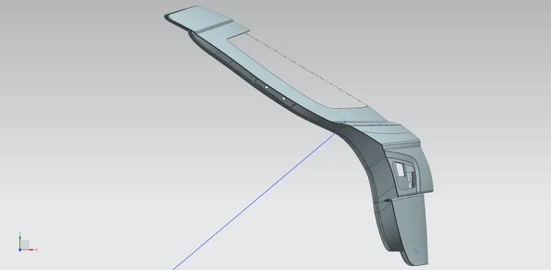
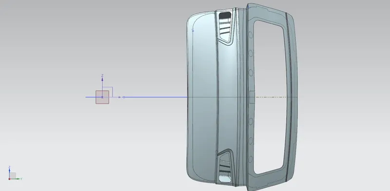
1.ISOMETRIC VIEW
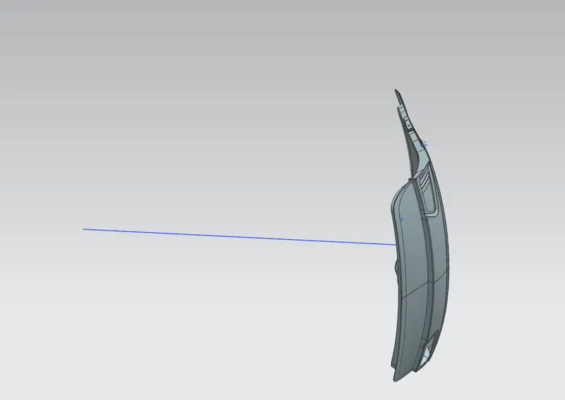
2.TOP VIEW
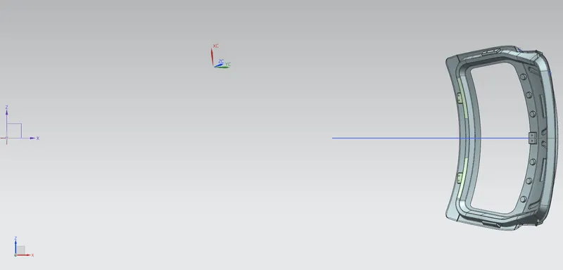
3.FRONT VIEW
4.RIGHT VIEW
DRAFT ANALYSIS
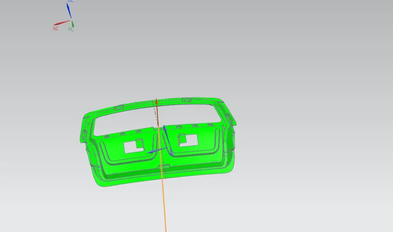
The Draft Analysis command enables you to detect if the part you drafted will be easily removed. This type of analysis is performed based on color ranges identifying zones on the analyzed element where the deviation from the draft direction at any point, corresponds to specified values
The draft analysis in our case of back door design is as shown in below figure,
CONCLUSSION
And hence we have designed the back door and its components successfully and we have understood the various features and design considerations of the backdoor.