Design of backdoor
AIM
To design Back Door of a vehicle using the provided styling surface and appropriate design methodologies and also design the necessary reinforcements and embossed.
INTRODUCTION
A door is generally used for entry and exit to the vehicle. Back door is one of the Door used in automobile at the back, which is used to provide an entry or exit to luggage or passengers into the vehicle through back side. In most of the vehicles, Back doors are supported by gas stay at open condition and also reduces the human effort required. In some Luxury vehicles power Back doors are used which are operated by electric motor, this type of systems called Powered Trunk Lift System. Hatchback or Station Wagons comes with 3 or 5 door models, in which hatch is called as door because it enters in the passenger’s compartment. This nomenclature is generally used in Europe countries. In case of safety, the back door is design should meet the safety requirement for the rear collision.
TYPE OF BACK DOORS
1. TOP MOUNTED
The Top Mounted Back Doors are generally used in pickup trucks, station wagon and sport utility vehicles. In modern vehicles Top Mounted tail gate systems are used which are of both gas stay and powered type. This type of Tailgate provides greater rear visibility as compared to side mounted or bar doors.
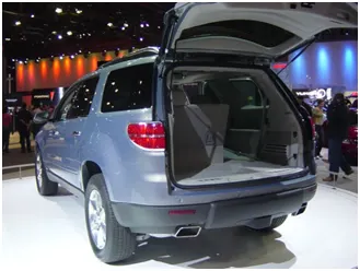
Figure 1 Top Mounted Tailgate
2. Side mounted
Side mounted Tailgates are generally used in Vans, MPVs, SUVs etc. These Side mounted doors are much easier as compared to Top mounted doors. These Tailgates are generally small in size and can easily be accessed.

Figure 2 Side Mounted Tailgate
TYPE OF MECHANISM USED FOR TAILGATE SUPPORT
1. GAS STAY
It is most commonly used Tailgate support system in which a Gas Stay is mounted at side of door to provide support to the Tailgate at open condition and also reduce the applied effort to open the Tailgate.
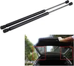
Figure 3 Gas stay and mounting
2. POWERED LIFT SYSTEM
The power Lift system for back door is the system used in most of Luxurious vehicles which automate the tailgate with the help of electric motor and wireless switch which is operated by the Key remote.
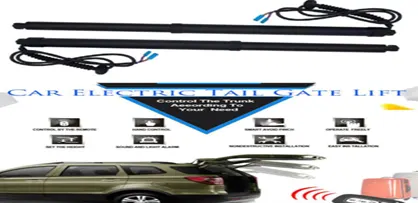
Figure 4 Electric Tailgate Lift system
MANUFACTURING PROCESS
The conventional tailgate assemblies are made by stamped metal panels welded together to form tailgate. Latch and striker system are mounted to provide it locking system. The steel tailgate assembly provide a durable and secure closure for the pickup bed.
STAMPING PROCESS
Stamping process is used on sheet metals to provide them a defined shape by using a die. However, normally the processes used are Blanking, Drawing, Piercing, Forming, Notching, Trimming Heming etc. Blanking is used to initial approximate form of the part in flat sheet. Drawing is used to attain depth related form.
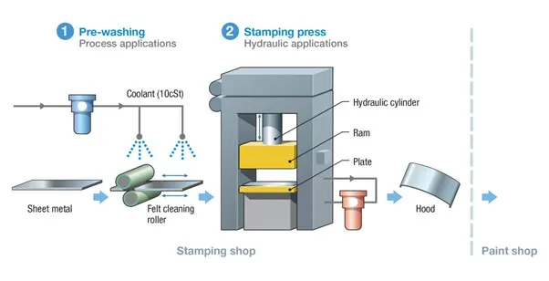
Figure 5 Stamping Press
· BLANKING PROCESS
This process is used at initial stage of stamping, where the metal sheet is cut into different shape and size as required for the further stapes.
· PIERCING
When a metal sheet requires slots, holes or other cutouts then we need Piercing. Piercing process is used to produce slots and cutouts simultaneously with Blanking. In which a requisite shape is punched out on the metal sheet.
· DRAWING
In Drawing process, a Die is punched with a punch force on the metal sheet to provide the primary shape of the part. If the depth of the part is less than the primary opening then it is considered as Shallow Drawing process and if the primary depth is greater than the opening than it considered as Deep Drawing Process.
· BENDING
As the name Bending, this process is used to bend the sheet metal. For bending, the part is placed on a specially designed Die and a Ram push against the metal and provides the required Bend. Bending is performed after drawing, as attempting to punch an already bent piece of metal causes the entire part to deform.
· HEMMING
Hemming process is used to join the outer and inner panel together. In this process the flange of outer panel is bended and folded over the inner panel. The accuracy of the operation affects the appearance of the outer surface. Therefore, it is a critical factor in the final quality of a finished vehicle.
There are different ways to hem a sheet some of them are as below,
(1) CONVENTIONAL DIE HEMMING: In Conventional Die Hemming the flange is folded over the entire length with a Hemming Tool.
(2) ROLLER HEMMING: For the roller hemming an Industrial robot is used with rollers at different angles to roll the flange of outer panel.
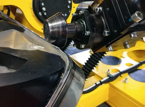
Figure 6 Roller Hemming
MATERIAL FOR BODY PANELs
The material for body panel is an important factor. It consists specific characteristics to meet the industry challenges like Rationalisation of specifications for leaner inventory, improved formability for reduced rejection rate and better quality. Higher Strength Low Alloy (HSLA) steel is preferred for weight reduction and resulting better fuel economy. Other characteristics like yield stress, Toughness, fatigue strength, dent resistance and corrosion resistance are also kept in mind during the selection of material for outer and inner panel of back door.
An intensive research and Development are going on for the alternate materials, manufacturing processes and stamping tools for sheet metal components with the objective of cost cutting and weight reduction for better fuel economy. Simultaneously, the steel content of the vehicle is falling with the use of Aluminium and other new researched materials such as plastic polymers and alloys. Aluminium provides more strength and it is lighter than the steel which reduces the overall weight of the vehicle. A reduction of 30% in weight is achievable if the same strength, stiffness and stability is required using Aluminium instead of Steel. Possibility of significant reduction in Die cost will be another advantage with Aluminium. However, problems related to strength, serviceability, manufacturability and above all the cost require effective solutions before the acceptance of Aluminium as a substitute to steel for body panels.
BACK DOOR DESIGNING USING NX CAD
Components
1. Outer upper panel
2. Outer lower panel
3. Inner panel
4. Hinge mounting Reinforcement
5. Gas stay mounting Reinforcement
6. Wiper motor mounting Reinforcement
7. Latch and Striker mounting Reinforcement
PROCEDURE
First open the part file into NX software and check all irregularities and repair where it needed. After the repair work the outer panel is separated into two parts one is Upper panel and another is lower panel. Then we start to create the first part of the BACK DOOR ASSEMBLY,
1. OUTER UPPER PANEL
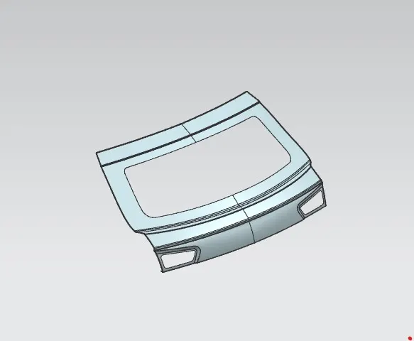
Figure 7 Outer Upper Panel
· Using Wave Geometry Linker option in assembly we just copy the upper outer panel aesthetic surface from the improved surface data.
· After that we create an offset surface at 2.65 mm distance to create a Heming surface and trimmed it as required then using Law extension comment created a third surface.
· Then we Blend the all three surfaces using Face Blend command.
· After that we mirrored the geometry and sewed them.
· At last, we thicken the final surface to a thickness of 0.75 mm
2. OUTER LOWER PANEL
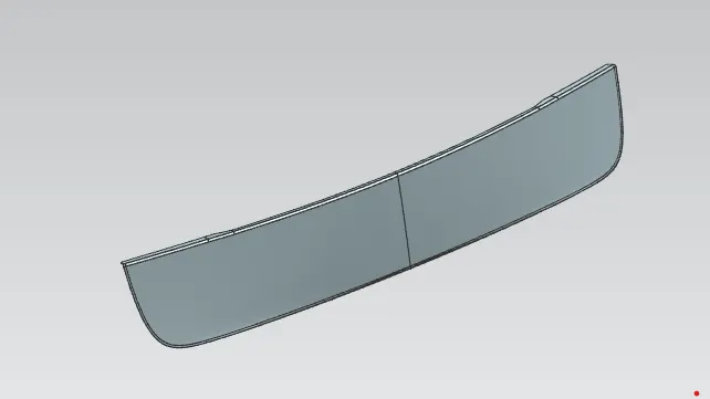
Figure 8 Outer Inner Panel
· For creating Lower panel, we just done the Copy using Wave Geometry Linker command and then create an offset for Hemming surface and trimmed it as required.
· After that we done the Face blend and sew the surface to join both parts.
· At last, we thicken it to 0.75 mm.
3. INNER PANEL
· First, we copy the outer aesthetic surface using wave geometry linker command then we created a Tooling axis to do a draft analysis for inner panel.
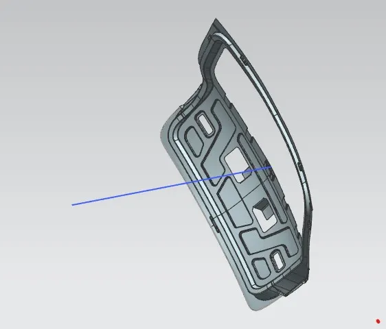
Figure 9 Tooling axis
· After creating Tooling axis, we offset the surface and done some operations using commands like offset on curve, trim, bridge curve and studio surface and created the Silling Flange.
· After creating Silling Flange, we just took the edge of the Silling Flange and do a Law Extension to create a connecting surface.
· After this we blend the connecting flange with the silling flange and trimmed it with the upper offset surface.
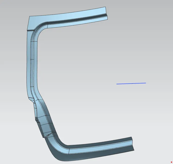
Figure 10 Trimmed part of silling flange with connecting flange and outer flange
· After all these steps, we create a surface for lower portion using commands like bridge curve and studio surface then sewed the surfaces together.
· Now we created a flange on lower portion to provide mastic to the outer and inner surface which provides strength to the assembly.
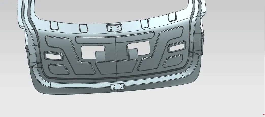
Figure 11 Embosses and mounting for mastics
· After that we created embosses on the lower surface to reduce the stress concentration during an impact and it also gives strength to the whole assembly.
· After that we created mountings for hinge and gas stay.
· After this we just done mirror and sew it.
· After sewing the surfaces, we created the wiper motor mounting and latch and striker mounting for mount the parts.
· We created a trajectory for knowing the movement of the back door to fix the latch and striker at proper place.
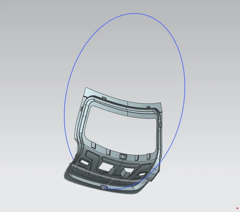
Figure 12 Latch and Striker Trajectory
· At last, we thicken the whole part to a thickness of 0.75 mm.
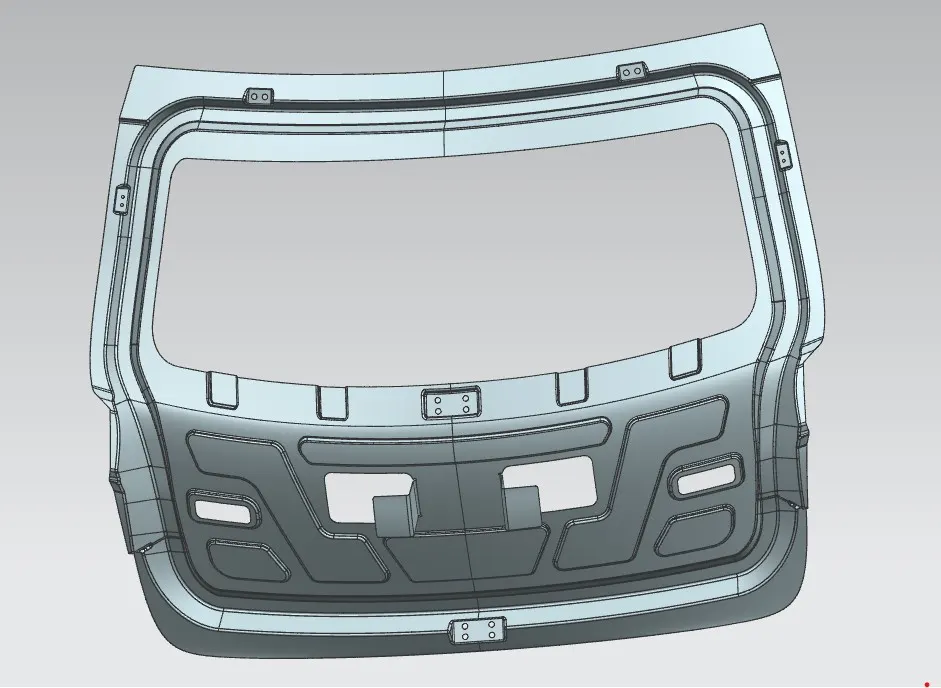
Figure 13 Inner Panel with all mounting
4. HINGE MOUNTING REINFORCEMENT
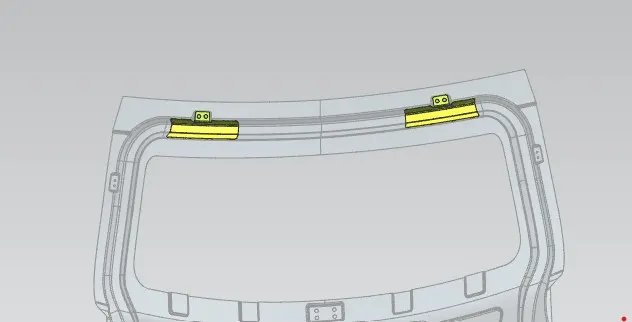
Figure 14 Hinge mounting Reinforcement
· First, we copy the Inner part.
· For Hinge mounting Reinforcement, we extract the hinge mounting and extend the edges for providing better support to the hinges.
· After this trimmed the extra part which is not needed.
· Then Repair the sharp corners and thicken the part up to 1.5 mm to provide strength.
5. GAS STAY MOUNTING REINFORCEMENT
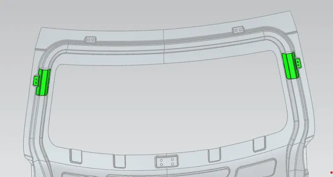
Figure15 Gas Stay Mounting Reinforcement
· For Gas Stay Mounting Reinforcement First, we Copy the Inner part.
· Then we extract the Gas Stay Mounting and extend the edges.
· Trimmed the unnecessary part of the extracted part.
· Then repair the sharp corners and thicken the sheet to 1.5mm.
6. WIPER MOTOR MOUNTING REINFORCEMENT
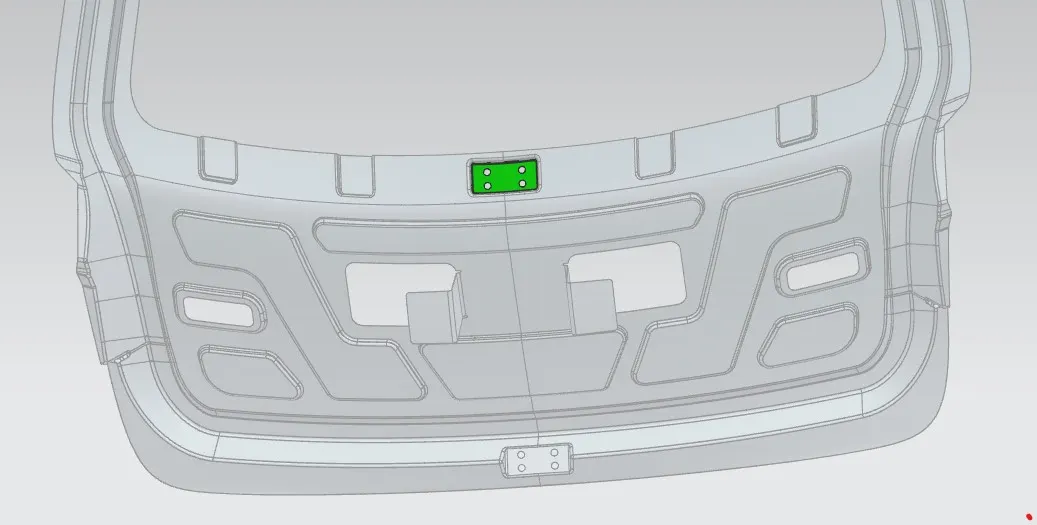
Figure 16 Wiper Motor Mounting Reinforcement
· For Wiper Motor Mounting Reinforcement First, we copy the Inner part.
· After this we extract the wiper motor mounting.
· Then we thicken it ton 1.5 mm.
7. LATCH AND STRIKER MOUNTING REINFORCEMENT
Figure 17 Latch and Striker Mounting Reinforcement
· For this Reinforcement we extract the mounting of Latch and Striker.
· Then we extend the edges of the extracted body.
· Then trimmed the body as we needed
· At last Repair the sharp corners and thicken the part to 1.5 mm.
HEMMING
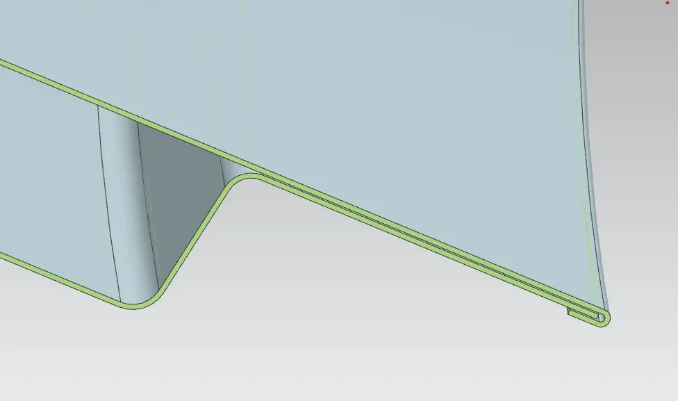
Figure 18 Hemming of Outer and Inner Panel
Hemming is a joining process used to join inner and outer panel of the back door. The gap between the outer and inner sheet is 0.2mm. To increase crash resistance the gap between the Panels is filled with a high strength adhesive which also prevent from corrosion. The sharp corners are repaired by giving hemming reliefs.
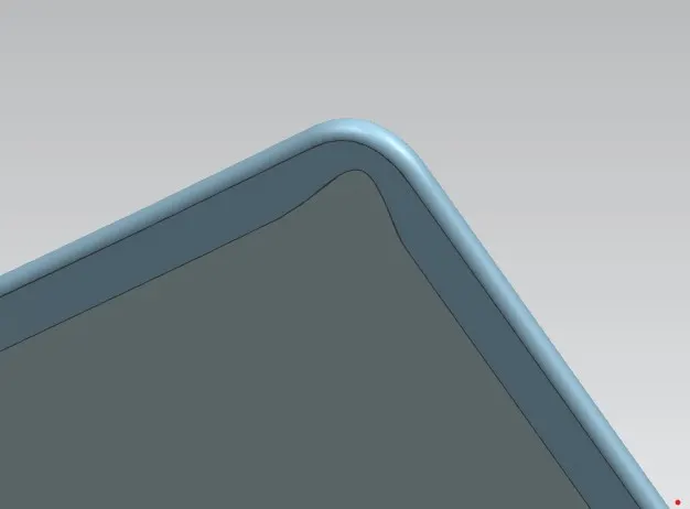
Figure 19 Hemming Reliefs
DRAFT ANALYSIS
This process is used to check whether the part can be made easily using a tooling axis or not. For that we create a tooling axis along with the inner panel and check that it is feasible with provided angles and data or not.
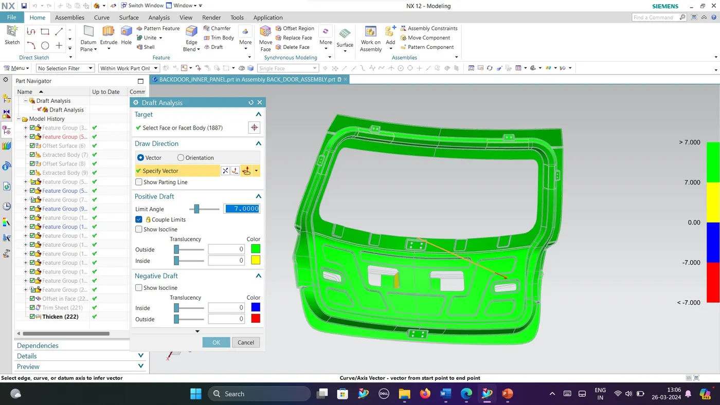
Figure 20 Draft analysis
In the Figure 20, The draft analysis is shown in which we are checking that the part is feasible with the tooling axis. The Green colour shows that the draft angle is 7 degree or greater, yellow shows that draft angle is between 0 to 7 degrees, blue shows that the draft angle is between -7 to 0 degrees and red shows that draft angle is -7 or lower than this.
As per design condition the Draft angle is 7 degrees of greater than this. So, from the draft analysis we checked that the draft angle is 7 degree or Greater than this.
CONCLUSION
As per the given data and the design consideration we have successfully designed the BACK DOOR and their REINFIRCEMENTS.
Note: The Part and Assemblyt file that are converted into a zip file is uploaded on Drive and the link is attached below-https://drive.google.com/file/d/1G87QSkUwC-mH0EtqgOKUGpz6fj9-VeRy/view?usp=sharing